Magnescale SJ300 SJ300 User manual

SJ300 Series
Instruction Manual / Bedienungsanleitung /
Scale Unit / Maßstabseinheit /
Read all the instructions in the manual carefully before use and strictly follow them.
Keep the manual for future references.
Lesen Sie die ganze Anleitung vor dem Betrieb aufmerksam durch und folgen Sie
beim Betrieb des Geräts den Anweisungen. Bewahren Sie diese Bedienungsanleitung
zum späteren Nachlesen griffbereit auf.

[For U.S.A. and Canada]
THIS CLASS A DIGITAL DEVICE
COMPLIES WITH PART15 OF THE
FCC RULES AND THE CANADIAN
ICES-003. OPERATION IS
SUBJECT TO THE FOLLOWING
TWO CONDITIONS.
(1) THIS DEVICE MAY NOT
CAUSE HARMFUL
INTERFERENCE, AND
(2) THIS DEVICE MUST ACCEPT
ANY INTERFERENCE
RECEIVED, INCLUDING
INTERFERENCE THAT
MAY CAUSE UNDERSIGNED
OPERATION.
CET APPAREIL NUMERIQUE DE
LA CLASSE A EST CONFORME A
LA NORME NMB-003 DU CANADA.
[For the customers in Australia]
Australian EMC Notice
This product complies with the
following Australian EMC standards.
AS/NZS 4252.1 /94 EMC Generic
Immunity Part1
AS/NZS 2064 /92 Emission
Standard for ISM Equipment
[ For EU and EFTA countries ]
CE Notice
Marking by the symbol CE indicates
compliance with the EMC directive of
the European Community. This
marking shows conformity to the
following technical standards.
EN 55011 Group 1 Class A / 98 :
"Limits and methods of
measurement of radio
disturbance characteristics of
industrial, scientific and medical
(ISM) radio-frequency
equipment"
EN 61000-6-2 / 99 :
"Electromagnetic compatibility
(EMC) - Part 6-2 : Generic
standards - Immunity for
industrial environments"
警告
本装置を機械指令(EN60204-1)の適
合を受ける機器にご使用の場合は、
その規格に適合するように方策を講
じてから、ご使用ください。
Warning
When using this device with
equipment governed by Machine
Directives EN 60204-1, measures
should be taken to ensure
conformance with those directives.
Warnung
Wenn dieses Gerät mit
Ausrüstungsteilen verwendet wird,
die von den Maschinenrichtlinien EN
60204-1 geregelt werden, müssen
Maßnahmen ergriffen werden, um
eine Übereinstimmung mit diesen
Normen zu gewährleisten.
SJ300 Series
(E) (1)
Safety Precautions
Magnescale Co., Ltd. products are designed in full consideration of safety. However, improper
handling during operation or installation is dangerous and may lead to fire, electric shock or
other accidents resulting in serious injury or death. In addition, these actions may also worsen
machine performance.
Therefore, be sure to observe the following safety precautions in order to prevent these types
of accidents, and to read these “Safety Precautions” before operating, installing, maintain-
ing, inspecting, repairing or otherwise working on this unit.
Warning Indication Meanings
The following indications are used throughout this manual, and their contents should be
understood before reading the text.
Warning
Failure to observe these precautions may lead to fire, electric shock or other accidents re-
sulting in serious injury or death.
Caution
Failure to observe these precautions may lead to electric shock or other accidents resulting
in injury or damage to surrounding objects.
Symbols requiring attention
Symbols prohibiting actions
Symblos specifying actions
CAUTION ELECTRICAL
SHOCK
FINGER
JAM
UNPLUGGING
DO NOT
DISASSEMBLE

SJ300 Series
(2) (E)
Warning
•Do not use this unit with voltages other than the specified supply voltage as this
may result in fire or electric shock.
•Do not perform installation work with wet hands as this may result in electric
shock.
•Do not disassemble or modify the unit as this may result in injury or damage the
internal circuits.
Caution
•Be sure to check the machine and device conditions to ensure work safety before
working on the machine.
•Be sure to cut off the power supply and other sources of drive power before in-
stalling the working on the machine. Failure to do so may result in fire or accidents.
•When turning on the power supply, etc. to operate the machine, take care not to
catch your fingers in peripheral machines and devices.

SJ300 Series
(E) (3)
Handling Precautions
Installation precautions
When installing this unit, care should be given to the following points to prevent noise and
electromagnetic wave interference from other equipment.
1. Do not pass lead and connection cables through the same ducts as power lines.
2. Be sure to install the unit at least 0.5 m/1.6 ft or more away from high voltage or large
current sources or high-power relays.
3. Absolutely do not bring the unit near magnets or sources of electromagnetic waves.
•Magnet chucks and other sources of magnetic force of approx. 60 mT should be kept
at least 50 mm/2.0 in or more away from the shaft scale surface.
•If the unit must be installed close to sources of magnetic force, be sure to implement
adequate electromagnetic shielding countermeasures.
Installation place precautions
1. Mount the scale for more precise positioning as closely as possible to the workpiece or
to the object being measured.
(The farther the scale is mounted from workpiece, the greater the mechanical errors
grow.)
2. The scale unit should be used within an ambient temperature range of 0 to 40°C (104F°).
Avoid locations where the scale is exposed to direct sunlight and heat sources such as
motors.
3. Do not place anything on the mounted scale, or step on it: excessive force to the scale
causes trouble.

SJ300 Series
(4) (E)
Precautions for use under the following environments
1. When using water-miscible cutting fluid or when cutting non-metal
(ceramic, glass fiber, etc.) objects.
•Mount the scale so that it is not directly exposed to water-miscible cutting fluid or cutting
scraps.
•Attach a scale cover to prevent water-miscible cutting fluid mist or powder from entering
the inside of the scale.
2. When mounted on a forming machine or other machine that slides at
high speed for long periods within a specific area.
•Regularly apply oil or spray lubricant (CRC, WD40, etc.).
Be sure to implement the above measures when using the scale under the environments
noted in 1and 2above. Otherwise, quality cannot be assured.
General Precautions
When using Magnescale Co., Ltd. products, observe the following general precautions along
with those given specifically in this manual to ensure proper use of the products.
•Before and during operations, be sure to check that our products function properly.
•Provide adequate safety measures to prevent damage in case our products should develop
a malfunction.
•Use outside indicated specifications or purposes and modification of our products will
void any warranty of the functions and performance as specified for our products.
•When using our products in combination with other equipment, the functions and
performance as noted in this manual may not be attained, depending upon the operating
environmental conditions. Make a thorough study of the compatibility in advance.

SJ300 Series
(E) i
Contents
1. Overview ....................................................................1
1-1. Introduction ....................................................................................................... 1
1-2. Main Features ................................................................................................... 1
1-3. Product Configuration ....................................................................................... 1
1-4. System Configuration ....................................................................................... 2
2. Name and Function of Each Part ............................. 3
2-1. Scale .................................................................................................................. 3
2-2. Cable (sold separately: CH33-**CPD/CED) .................................................. 4
3. Mounting ....................................................................5
3-1. Mounting precautions ....................................................................................... 5
3-1-1. Mounting locations ........................................................................ 5
3-1-2. Other Precautions ........................................................................... 6
3-2. Mounting Procedure ......................................................................................... 8
4. Specifications ..........................................................13
4-1. Scale ................................................................................................................ 13
4-2. Cable ............................................................................................................... 14
5. Dimensions ..............................................................15

SJ300 Series
ii (E)

SJ300 Series
(E) 1
1. Overview
1-1. Introduction
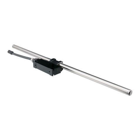
•The SJ300 series is a lineup of linear scales featuring self-adjusting reader head and a
shaft-type magnetic scale.
•A dedicated output cable (CH33-**CPD/CED) is sold separately. The length of the
output cable can be selected by the user. (Maximum cable length: 15 m/49.2 ft)
1-2. Main Features
Easy mounting
The head with self-adjusting reader head and dedicated scale bracket with wide allowable
mounting range enable the scale to be mounted in significantly less time.
No electrical adjustments
All electrical circuits, including interpolation circuits, are incorporated into the slider so that
no electrical adjustments are needed when changing the cable length or mounting the scale.
Resistant to oil and dust
The magnetic scale uses an exclusive Magnescale Co., Ltd. design for providing a structure
that is resistant to oil and dust.
1-3. Product Configuration
Scale Shaft scale ............................................................................................. 1
Head ...................................................................................................... 1
Accessories Scale bracket 1 set
Scale brackets A, B, C ......................................................2 each
Hexagonal bolts M5×20 ............................................................ 6
Hexagonal nuts M5 ................................................................... 6
Flat washers W8 ....................................................................... 4
For securing scale head and cable
Cable clamp (small) .................................................................. 1
Cable clamps (large) ................................................................. 4
HSB M4×15 .............................................................................. 7
HSB M4×25 .............................................................................. 2
HSB M6×25 .............................................................................. 2

SJ300 Series
2(E)
1-4. System Configuration
Model Configuration
Scale
Model name Measuring length (ML) Model name Measuring length (ML)
(mm/inch) (mm/inch)
SJ300-005 50/1.9" SJ300-065 650/25.5"
SJ300-010 100/3.9" SJ300-075 750/29.5"
SJ300-015 150/5.9" SJ300-080 800/31.4"
SJ300-020 200/7.8" SJ300-085 850/33.4"
SJ300-025 250/9.8" SJ300-095 950/37.4"
SJ300-030 300/11.8" SJ300-105 1050/41.3"
SJ300-035 350/13.7" SJ300-125 1250/49.2"
SJ300-040 400/15.7" SJ300-140 1400/55.1"
SJ300-045 450/17.7" SJ300-160 1600/62.9"
SJ300-050 500/19.6" SJ300-185 1850/72.8"
SJ300-055 550/21.6" SJ300-205 2050/80.7"
SJ300-060 600/23.6" SJ300-220 2200/86.6"
Connecting cable (sold separately)
Model name Cable length (m/ft)
CH33-03CPD/CED 3/9.8'
CH33-05CPD/CED 5/16.4'
CH33-10CPD/CED 10/32.8'
CH33-15CPD/CED 15/49.2'
Scale
SJ300 series
Connecting cable
(sold separately)
CH33-**CPD/CED
Counter unit
(sold separately)
LH70/LH71 series

SJ300 Series
(E) 3
2. Name and Function of Each Part
2-1. Scale
Head
No. Name Function
1Head holder Includes built-in detector sensor using MR element.
2Slider This receives signals from the head and includes a circuit
for generating A/B quadrature signals.
3Holder bracket Secures the head holder and slider. This prevents
unnecessary force from being applied to the head holder
during installation. It serves as a rough guide for head
and scale installation, and so do not remove it until scale
mounting is completed.
4Shaft scale The structure has an internal magnetic band for magnetic
recording. The outer surface has a stainless steel pipe
structure that also provides protection.
5Cable connector Connects the cable.
Do not apply excessive pressure to the connector pins.
This can cause them to break.
6Scale brackets These brackets are used to mount the shaft scale.
A, B, and C There are three types: A, B, and C.
7Status lamp This is a lamp for checking the scale mounting.

SJ300 Series
4(E)
2-2. Cable (sold separately: CH33-**CPD/CED)
Input connector
(SJ300 side)
Output connector
(Counter unit side)

SJ300 Series
(E) 5
3. Mounting
3-1. Mounting precautions
To prevent problems due to noise, mount the scale and slider so that they are connected to
the machine ground.
Center offset:
±0.5 mm/0.02 in or less
Head holder center and
shaft scale during mounting
ML
Do not mount the scale bracket any further
inside from here (head side).
9±3 mm
/0.35"±0.12"
3-1-1. Mounting locations
Shaft scale and head holder locational relationship
Head movable range
Be sure that the measurement length (ML) is within the value shown in “5. Dimensions.”
Mounting when the head movable range exceeds the scale maximum
operating length
Be sure to implement mechanical limiting mechanisms (such as stoppers).

SJ300 Series
6(E)
Where the scale is exposed to chips and cutting oil
It is recommended a protective cover as shown in the figure be provided to maintain the
scale’s high performance.
3-1-2. Other Precautions
•Do not disassemble.
•Do not apply excessive pressure or try to bend the scale or head.

SJ300 Series
(E) 7
•Do not bring magnet chucks or other strong magnetic sources near the scale.
•Do not pull strongly or put excessive pressure on the cable.
Bending radius:Cable moving part: r = 50 mm/2.0"
<When cable is secured>
Cable part: r = 20 mm/0.8", Armored cable part: r = 25 mm/1.0"
•To protect the head holder, do not remove the holder brackets until scale mounting is
complete.
Cable
Bending radius : r

SJ300 Series
8(E)
3-2. Mounting Procedure
This section describes the standard mounting procedure for mounting with reference to the
head. This is an effective mounting method when the scale mounting surface has a casting
surface finish.
1. Mounting scale bracket A
Be sure to maintain flatness of the mounting surface within the range below.
Refer to “5. Dimensions” for the mounting location.
2. Securing the cable
Check that the scale power supply is turned off, and then connect the cable to the
slider. When connecting, be careful that the connector pin does not get bent.
(Connector set screw M2.6: Tightening torque: 0.3 N
•
m)
After connecting the cable, be careful that no force is applied to it.
Flat washer
Scale bracket A
Table
Align the guide
Diameter:
16 mm/0.63" or more
Flatness:
0.1 mm/0.004" or less
Tap hole M8 depth:
15 mm/0.59" or more

SJ300 Series
(E) 9
3. Mounting the head
Refer to “5. Dimensions” for the mounting location. The slider can be mounted on
either side, and so mount it based on the direction that the cable is pulled out during
operation.
Mounting parallelism:0.1 mm/0.004"
Tightening torque:2.7 N
•
m
Hexagonal bolt 1
Hexagonal bolt 2
Hexagonal bolt 3
Scale bracket B
Scale bracket C
4. Mounting the scale brackets B and C
Attach the hexagonal bolts and hexagonal nuts to the scale brackets B and C on either
the right or left side, and assemble as shown in the figure. When attaching, temporarily
tighten hexagonal bolts 1, 2, and 3so that the brackets will not fall off.
5. Mounting the scale brackets B and C on the opposite side
In the same way as step 4, assemble scale brackets B and C on the other side.

SJ300 Series
10 (E)
6. Pass through the shaft scale
Move the table so that the head is near either the right or left scale bracket, and then
pass the shaft scale through the head and scale bracket.
If the shaft scale cannot be inserted, loosen the hexagonal bolts 1, 2, and 3enough
so that it can fit through.
7. Temporarily tighten hexagonal bolts 1, 2, and 3
Gently tighten hexagonal bolts 1, 2, and 3in that order while being careful not to
apply pressure to the head holder.
Move the table so that the head is near the scale bracket on the opposite side, and then
gently tighten the hexagonal bolts 1, 2, and 3, in that order, in the same way.
8. Tighten hexagonal bolts 1and 2
Loosen hexagonal bolt 3, and then tighten hexagonal bolts 1and 2using the same
procedure as step 7 while confirming that the shaft scale moves smoothly to the left and
right. Repeatedly move the table, and tighten the bolts gradually in an alternating fashion.
Tightening torque: 5.4 N
•
m
Tighten
Tighten
Hexagon bolt 3
Not parallel
to slider
NGOK

SJ300 Series
(E) 11
9. Securing the shaft scale
Determine the shaft scale position. To obtain stable signals, rotate and position the shaft
scale so that the head and shaft scale have the positional relationship shown in the
figure.
As shown in the figure, magnetic recording in the shaft scale is possible only for a
range of approximately 70 degrees (9 mm/0.35") in the circumferential direction. Note
that signals cannot be detected for positions that are not recorded magnetically.
Tighten the hexagonal bolts 3on both ends.
Tightening torque: 5.4 N
•
m
10. Removing the holder bracket
Pull the holder brackets to the right and left to remove.
11. Connecting the cable and counter unit
Connect the dedicated cable CH33-**CPD/CED directly to the counter unit LH70/
LH71 (set screws: inch type). The cable has a pin layout enabling direct connection to
the counter unit.
12. Turning on the power
Turn on the power of the counter unit LH70/LH71.
Head holder
Detector sensor
Recommended
setting range: 3 mm/0.12"
Shaft scale
Scale recording
range: 9 mm/0.35"
Scale position mark

SJ300 Series
12 (E)
13. Post-mounting check
Check that status lamp lights green and the count values are displayed properly over the
entire measuring length.
When the status lamp is turned off:
•Check the power voltage of the LH70/LH71.
•Check that the cable is not disconnected, only cables designated by Magnescale
Co., Ltd. are being used, and no cable extensions exceed the stipulated limit.
When the status lamp is lit red:
•Return to step 9, “Securing the shaft scale,” and check mounting again.
If the status lamp does not light green after checking the points above or the scale does
not count normally, contact the Customer service section.
Table of contents
Languages:
Other Magnescale Scale manuals

Magnescale
Magnescale SmartSCALE PQ10 Series User manual

Magnescale
Magnescale BS78 User manual

Magnescale
Magnescale RU97-2048 Z Series User manual

Magnescale
Magnescale PL25 User manual

Magnescale
Magnescale SR27A-AZ Series User manual

Magnescale
Magnescale SL700 Series User manual

Magnescale
Magnescale SR84 User manual

Magnescale
Magnescale SmartSCALE SQ47-Z Series User manual

Magnescale
Magnescale SmartSCALE SQ57 User manual

Magnescale
Magnescale SJ300 Series Owner's manual