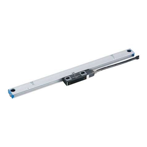
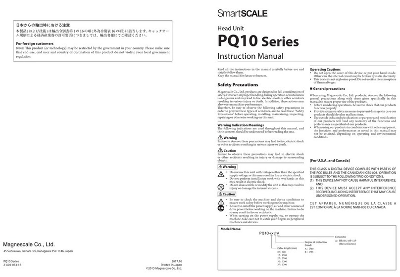
Magnescale SL700 Series User manual

SL700 Series
取扱説明書 / Instruction Manual / Bedienungsanleitung
スケール / Scale / Maßstab
お買い上げいただき、ありがとうございます。
ご使用の前に、この取扱説明書を必ずお読みください。
ご使用に際しては、この取扱説明書どおりお使いください。
お読みになった後は、後日お役に立つこともございますので、必ず保管してください。
Read all the instructions in the manual carefully before use and strictly follow them.
Keep the manual for future references.
Lesen Sie die ganze Anleitung vor dem Betrieb aufmerksam durch und folgen Sie
beim Betrieb des Geräts den Anweisungen. Bewahren Sie diese Bedienungsanleitung
zum späferen Nachlesen griffbereit auf.

このマニュアルに記載されている事
柄の著作権は当社にあり、説明内容
は機器購入者の使用を目的としてい
ます。
したがって、当社の許可なしに無断
で複写したり、説明内容(操作、保
守など)と異なる目的で本マニュア
ルを使用することを禁止します。
The material contained in this manual
consists of information that is the
property of Magnescale Co., Ltd. and
is intended solely for use by the
purchasers of the equipment
described in this manual.
Magnescale Co., Ltd. expressly
prohibits the duplication of any
portion of this manual or the use
thereof for any purpose other than the
operation or maintenance of the
equipment described in this manual
without the express written permission
of Magnescale Co., Ltd.
Le matériel contenu dans ce manuel
consiste en informations qui sont la
propriétéde Magnescale Co., Ltd. et
sont destinées exclusivement à
l'usage des acquéreurs de
l'équipement décrit dans ce manuel.
Magnescale Co., Ltd. interdit
formellement la copie de quelque
partie que ce soit de ce manuel ou son
emploi pour tout autre but que des
opérations ou entretiens de
l'équipement àmoins d'une
permission écrite de Magnescale
Co., Ltd.
Die in dieser Anleitung enthaltenen
Informationen sind Eigentum von
Magnescale Co., Ltd. und sind
ausschließlich für den Gebrauch
durch den Käufer der in dieser
Anleitung beschriebenen Ausrüstung
bestimmt.
Magnescale Co., Ltd. untersagt
ausdrücklich die Vervielfältigung
jeglicher Teile dieser Anleitung oder
den Gebrauch derselben für
irgendeinen anderen Zweck als die
Bedienung oder Wartung der in dieser
Anleitung beschriebenen Ausrüstung
ohne ausdrückliche schriftliche
Erlaubnis von Magnescale Co., Ltd.
(J) 1
SL700
1.仕様
使用温度範囲:0〜+45°C
保存温度範囲:−10〜+50°C
質量:15g/m
2.取付寸法図
注意
スケールとヘッドの
Magnescaleマークの
向きを同じにします。
単位:mm
0.05
SL700 Series
12.65
12
*PL101−N
−R
*PL101−RH
20
9
0.05
48
1.5
43.5
11.5
(20)
PL101
0.04
4
∅4.4
6
6.65
21
M
25
0.16 M
0.08 M
M: マシンガイド
オフセット: ±0.2
ヨー: ±0.2
有効長
全長 = 有効長 + 40
クリアランス: 0.35 ±0.1
ピッチ: ±0.1
ケーブル長: 300
センターマーク
ロール: ±0.2
200以下
ケーブル長: 3000
2 ×2-M3 深さ5
∅D穴(平行ピン挿入用)
原点マーク
原点位置
ヘッド
スケール
スケール厚み: 0.3

2(J)
SL700
3.注意事項
•この製品を取扱う際には、折ったり曲げたりしないよう充分ご注意ください。
•強力な磁気を発生させるものは、この製品の近くに設置しないでください。
•この製品は、周囲温度範囲0°C〜+45°C以内で、直射日光や熱源を避けてご使用
ください。
•この製品は、非磁性材の上に取付けてください。磁性材に取付けるときには、
3mm以上の厚みの非磁性層を設けてください。
•製品同士を接触させないでください。
•この製品の再取付けは行なわないでください。
•外部磁場の強さは0.5mT以下としてください。
4.取付方法
平行ピンによる方法
取付前準備
スケール取付面に、位置決めのための平行ピン挿入用穴を設けます。
推奨径:ピンø4 、穴ø4 。
•穴の間隔は200mm以下(図1)としてください。
•マシンガイドに対する穴の平行度は、50µm以下としてください。(取付寸法図
参照)
取付け
1. スケールを取付ける機械の近くに1時間ほど放置して、機械の温度になじませ
ます。
2. 清浄な布にアルコールを含ませて、取付面を脱脂し、ゴミ、埃等も取除いてく
ださい。
3. 平行ピンを挿入します。(図1)
4. スケールの向きを確認します。スケールとヘッドのMagnescaleマークの向き
が同じになるようにしてください。(図2)
−0.004
−0.012
+0.012
-0
0.05 M
図1
平行ピン
平行ピン
挿入用穴
スケール
取付面
M:マシンガイド
200mm以下
図2
Magnescaleマーク

(J) 3
SL700
5. スケールの原点位置を希望する位置に合わせ、スケール端にマーキングをしま
す。(図3)
6. 剥離紙を20mm程度はがします。(図4)
7. 2本以上の平行ピンに突き当てながらスケールを貼り付けます。(図5)
手順5で付けたマーキングとマーキングを付けた方のスケール端部を合わせ、
剥離紙をはがした20mm区間をしっかりと指で押さえ固定します。
8. 剥離紙を平行ピンの間隔分はがします。(図6)
9. スケールがたわまないように、かつ平行ピンに突き当てながらスケールを貼り
付けます。
10. 8.、9.を繰返し最後まで貼り付けます。
11. 平行ピンを抜きます。
12. スケールを全域にわたって指でしっかり押さえます。
図3
マーキング
図4
剥離紙
図5
突き当てる
突き当てる
図6
突き当てる

4(J)
SL700
段差による方法
他にもスケールの突き当てに段差を用いた方法があります。図7に段差の仕様を記
載します。
取付前準備
スケール取付面に、位置決めのための段差を設けます。
段差の高さは0.2〜0.3mm。(図7)
マシンガイドに対する段差の平行度は50µm以下としてください。(取付寸法図参
照)
取付け
1. 取付ける機械の近くに1時間ほど放置して、機械の温度になじませます。
2. 清浄な布にアルコールを含ませて、取付面を脱脂し、ゴミ、埃等も取り除いて
ください。
3. スケールの向きを確認します。スケールとヘッドのMagnescaleマークの向き
が同じになるようにしてください。
4. スケールの原点位置を希望する位置に合わせ、スケール端にマーキングをしま
す。
5. 剥離紙を20mm程度はがします。
6. 段差に突き当てながらスケールを貼り付けます。
スケールが段差に乗り上げないよう注意してください。
手順4で付けたマーキングとマーキングを付けた方のスケール端部を合わせ、
剥離紙をはがした20mm区間をしっかりと指で押さえ固定します。
7. 剥離紙を20〜30mmはがします。
8. 段差に突き当てながらスケールを貼り付けます。
9. 7.、8.を繰返し最後まで貼り付けます。
10. スケールを全域にわたって指でしっかり押さえます。
0.05 M
M:マシンガイド
0.2〜0.3mm
R0.1以下
図7

(E) 1
SL700
1. Specifications
Operating temperature range: 0°C to +45°C
Storage temperature range: −10°C to +50°C
Mass: 15 g/m
2. Installation Dimensional Diagram
NOTE
Align the Magnescale marks
on the scale and head so that
they are facing the same
direction.
Unit : mm
0.05
SL700 Series
12.65
12
*PL101-RH
*PL101-N
-R
20
9
0.05
48
1.5
43.5
11.5
(20)
PL101
0.04
4
ø4.4
6
6.65
21
M
25
0.16 M
0.08 M
Offset:
±
0.2
Ya w :
±
0.2
Effective length
Total length = Effective length + 40
Clearance: 0.35
±
0.1
Scale thickness: 0.3
Pitch:
±
0.1
Center mark
Roll:
±
0.2
200 or less
Cable length
Cable length: 3000
M: Machine guide
2 ×2-M3 Depth: 5
øD hole (for inserting parallel pin)
Reference position
Reference mark
Head
Scale

2(E)
SL700
3. Notes
•Take adequate care not to fold or bend the cables when using this product.
•Do not install equipment that generates strong magnetic waves in the vicinity of this
product.
•Use this product in an environment having an ambient temperature range of 0°C to +45°C
and that is not directly exposed to sunlight or heat sources.
•Install this product on top of non-magnetic materials. If installing on top of magnetic
materials, insert a non-magnetic layer having a thickness of at least 3 mm between the
product and magnetic materail.
•Avoid touching other scales or other parts of the scale with this product.
•Do not attempt to reinstall this product.
•Make sure that the external magnetic field does not exceed 0.5 mT.
4. Installation Procedure
Installation using parallel pins
Preparation
Make holes on the scale installation surface for inserting parallel pins so that positioning can
be performed.
Recommended diameter: Pin ø4 , Hole ø4 .
•The distance between the pins should be 200 mm or less. (Fig. 1)
•The parallelism of the holes with respect to the machine guide should be 50 µm or less.
(See the Installation Dimensional Diagram.)
Installation
1. Leave the scale near the machine where it will be installed for one hour so that the scale
can adjust to the machine temperature.
2. Use a clean cloth dipped in alcohol to wipe off any dirt, dust or oil from the installation
surface.
3. Insert the parallel pins. (Fig. 1)
4. Check the orientation of the scale. Position the scale so that the Magnescale marks on
the scale and head are facing in the same direction. (Fig. 2)
−0.004
−0.012
+0.012
-0
0.05 M
Fig. 1
Parallel pin M: Machine guide
Scale installation
surface
200 mm or less
Parallel pin
insertion
hole
Magnescale marks
Fig. 2

(E) 3
SL700
5. Align the scale with the desired scale reference position, and then mark this position at
the end of the scale. (Fig. 3)
6. Peel off about 20 mm of the backing paper. (Fig. 4)
7. Affix the scale while making contact with two or more parallel pins. (Fig. 5)
Align the mark made in step 5 with the scale end where the marking was made, and
then firmly press down the 20 mm of peeled backing paper with your fingers.
8. Peel off the backing paper to the position where the next parallel pin is reached. (Fig. 6)
9. Affix the scale while making contact with the parallel pin and being careful that firm
contact is maintained.
10. Repeat steps 8 and 9 until the entire length of the scale is affixed.
11. Remove the parallel pins.
12. Press down the entire length of the scale with your fingers.
Fig. 4
Marking
Fig. 3
Backing paper
Make contact
Make contact
Make contact
Fig. 5 Fig. 6

4(E)
SL700
Installation using a raised surface
The scale can also be installed using a raised surface making contact with the scale. The
specifications for the raised surface are shown in Fig. 7.
Preparation
Set a raised surface on the scale installation surface so that positioning can be performed.
The height of the raised surface should be from 0.2 to 0.3 mm. (Fig. 7)
The parallelism of the raised surface with respect to the machine guide should be 50 µm or
less. (See the Installation Dimensional Diagram.)
Installation
1. Leave the scale near the machine where it will be installed for one hour so that the scale
can adjust to the machine temperature.
2. Use a clean cloth dipped in alcohol to wipe off any dirt, dust or oil from the installation
surface.
3. Check the orientation of the scale. Position the scale so that the Magnescale marks on
the scale and head are facing in the same direction.
4. Align the scale with the desired scale reference position, and then mark this position at
the end of the scale.
5. Peel off about 20 mm of the backing paper.
6. Affix the scale while making contact with the raised surface.
Be careful that the scale does not get on top of the raised surface.
Align the mark made in step 4 with the scale end where the marking was made, and
then firmly press down the 20 mm of peeled backing paper with your fingers.
7. Peel off the backing paper by 20 to 30 mm.
8. Affix the scale while making contact with the raised surface.
9. Repeat steps 7 and 8 until the entire length of the scale is affixed.
10. Press down the entire length of the scale with your fingers.
0.05 M
Fig. 7
R0.1 or less
M: Machine guide
0.2~0.3mm

(G) 1
SL700
1. Technische Daten
Betriebstemperaturbereich: 0°C bis +45°C
Lagertemperaturbereich: −10°C bis +50°C
Masse: 15 g/m
2. Installations-Maßzeichnung
Einheit : mm
Hinweis
Die Magnescale-Schriftzüge
auf Maßstab und Kopf
müssen in die gleiche
Richtung weisen.
0.05
SL700 Series
12,65
12
*PL101-RH
*PL101-N
-R
20
9
0.05
48
1.5
43,5
11,5
(20)
PL101
0.04
4
ø4,4
6
6,65
21
M
25
0.16 M
Maßstabsdicke: 0,3
0.08 M
Versatz:
±
0,2
Gieren:
±
0,2
øD-Loch (für Parallelstift)
Effektive Länge
Gesamtlänge = Effektive Länge + 40
Abstand: 0,35 ±0,1
200 oder weniger
Stergung:
±
0,1
Kabellänge: 300
Mittenmarke
2 ×2-M3 Tiefe: 5
Rollen:
±
0,2
Kabellänge: 3 000
M: Maschinenführungsbahn
Referenzpunktmarkierung
Referenzpunktposition
Lesekopf
Maßstab

2(G)
SL700
3. Hinweise
•Achten Sie darauf, dass die Kabel bei Benutzung dieses Produkts nicht geknickt oder
gebogen werden.
•Installieren Sie keine Geräte, die starke Magnet-felder erzeugen, in der Nähe dieses
Produkts.
•Benutzen Sie dieses Produkt an einem Ort mit einer Umgebungstemperatur von 0°C bis
+45°C, der keinem direkten Sonnenlicht oder Wärmequellen ausgesetzt ist.
•Installieren Sie dieses Produkt auf nicht-magnetischem Material. Ist die Installation auf
magnetischem Material unumgänglich, ist eine nicht-magnetische Zwischenlage von
mindestens 3 mm Dicke zwischen das Produkt und das magnetische Materail einzufügen.
•Achten Sie darauf, dass dieses Produkte nicht mit anderen Teilen des Maßstabs oder
anderen Maßstäben in Berührung kommt.
•Versuchen Sie nicht, dieses Produkt erneut zu installieren.
•Magnetische Fremdfelder dürfen eine Gröse von 0,5 mT nicht überschreiten.
4. Installationsverfahren
Installation mit Parallelstiften
Vorbereitung
Bohren Sie Löcher auf der Maßstab-Installationsfläche für die Parallelstifte, so dass eine
Positionierung durchgeführt werden kann.
Empfohlener Durchmesser: Stift ø4 , Loch ø4
•Der Abstand zwischen den Stiften sollte höchstens 200 mm betragen. (Abb. 1)
•Die Parallelität der Bohrung in Bezug auf die Maschinenführung sollte höchstens 50 µm
betragen. (Siehe die Installations-Maßzeichnung.)
Installation
1. Lassen Sie den Maßstab etwa eine Stunde lang in der Nähe der Maschine, an der er
angebracht werden soll, liegen, damit er die Maschinentemperatur annimmt.
2. Verwenden Sie ein sauberes, mit Alkohol angefeuchtetes Tuch, um etwaigen Schmutz,
Staub oder Öl von der Montagefläche abzuwischen.
3. Setzen Sie die Parallelstifte ein. (Abb. 1)
4.
Überprüfen Sie die Ausrichtung des Maßstabs. Richten Sie den Maßstab so aus, dass die
Magnescale-Schriftzüge auf Maßstab und Kopf in die gleiche Richtung weisen. (Abb. 2)
Parallelstift M: Maschinenführungsbahn
Maßstab-
Installationsfläche
maximal 200 mm
Parallelstift-
Passbohrung
Abb. 1
−0.004
−0.012
+0.012
-0
0.05 M
Magnescale-Marken
Abb. 2

(G) 3
SL700
5. Richten Sie den Maßstab auf die gewünschte Maßstabs-Bezugsposition aus, und
markieren Sie dann diese Position am Ende des Maßstabs. (Abb. 3)
6. Ziehen Sie etwa 20 mm des Schutzpapiers ab. (Abb. 4)
7. Bringen Sie den Maßstab so an, dass er Kontakt mit mindestens zwei Parallelstiften hat.
(Abb. 5)
Richten Sie die in Schritt 5 gemachte Markierung auf das Maßstabsende aus, an dem
die Markierung vorgenommen wurde, und drücken Sie dann die 20 mm des abgezogenen
Schutzpapiers mit den Fingern fest nieder.
8. Ziehen Sie das Schutzpapier bis zu der Position des nächsten Parallelstifts ab. (Abb. 6)
9. Bringen Sie den Maßstab so an, dass er Kontakt mit dem Parallelstift hat, und achten
Sie darauf, dass fester Kontakt beibehalten wird.
10. Wiederholen Sie die Schritte 8 und 9, bis die gesamte Länge des Maßstabs angebracht
ist.
11. Entfernen Sie die Parallelstifte.
12. Drücken Sie den Maßstab auf seiner gesamten Länge mit den Fingern an.
Markierung
Abb. 3
Schutzpapier
Abb. 4
Kontakt
Abb. 5 Abb. 6
Kontakt
Kontakt

4(G)
SL700
0.05 M
Installation mit erhabener Fläche
Der Maßstab kann auch mittels einer erhabenen Fläche installiert werden, die Kontakt mit
dem Maßstab hat. Die Spezifikationen für die erhabene Fläche sind in Abb. 7 angegeben.
Vorbereitung
Setzen Sie eine erhabene Fläche auf die Maßstab-Installationsfläche, so dass eine
Positionierung durchgeführt werden kann.
Die Höhe der erhabenen Fläche sollte 0,2 bis 0,3 mm betragen. (Abb. 7)
Die Parallelität der erhabenen Fläche in Bezug auf die Maschinenführung sollte höchstens
50 µm betragen. (Siehe die Installations-Maßzeichnung.)
Installation
1. Lassen Sie den Maßstab etwa eine Stunde lang in der Nähe der Maschine, an der er
angebracht werden soll, liegen, damit er die Maschinentemperatur annimmt.
2. Verwenden Sie ein sauberes, mit Alkohol angefeuchtetes Tuch, um etwaigen Schmutz,
Staub oder Öl von der Montagefläche abzuwischen.
3. Überprüfen Sie die Ausrichtung des Maßstabs. Richten Sie den Maßstab so aus, dass
die Magnescale-Schriftzüge auf Maßstab und Kopf in die gleiche Richtung weisen.
4. Richten Sie den Maßstab auf die gewünschte Maßstabs-Bezugsposition aus, und
markieren Sie dann diese Position am Ende des Maßstabs.
5. Ziehen Sie etwa 20 mm des Schutzpapiers ab.
6. Bringen Sie den Maßstab so an, dass er Kontakt mit der erhabenen Fläche hat.
Achten Sie darauf, dass der Maßstab nicht auf die erhabene Fläche gelangt.
Richten Sie die in Schritt 4 gemachte Markierung auf das Maßstabsende aus, an dem
die Markierung vorgenommen wurde, und drücken Sie dann die 20 mm des abgezogenen
Schutzpapiers mit den Fingern fest nieder.
7. Ziehen Sie das Schutzpapier um 20 bis 30 mm ab.
8. Bringen Sie den Maßstab so an, dass er Kontakt mit der erhabenen Fläche hat.
9. Wiederholen Sie die Schritte 7 und 8, bis die gesamte Länge des Maßstabs angebracht
ist.
10. Drücken Sie den Maßstab auf seiner gesamten Länge mit den Fingern an.
Abb. 7
R0.1 oder weniger
M: Maschinenführungsbahn
0.2~0.3mm

フリガナ
電話 - - 印
お買上げ店住所・店名
〒 電話 - -
お買上げ日
年月日
本 体 1
年
型
名
期
間
保
証
お
客
様
お
名
前
ご
住
所
様
保 証 書
保証規定
z保証の範囲
q取扱説明書、本体添付ラベル等の注意書に従った正
常な使用状態で、保証期間内に故障した場合は、無
償修理いたします。
w本書に基づく保証は、本商品の修理に限定するもの
とし、それ以外についての保証はいたしかねます。
x保証期間内でも、次の場合は有償修理となります。
q火災、地震、水害、落雷およびその他天災地変によ
る故障。
w使用上の誤りおよび不当な修理や改造による故障。
e消耗品および付属品の交換。
r本書の提示が無い場合。
t本書にお買い上げ日、お客様名、販売店名等の記入
が無い場合。(ただし、納品書や工事完了報告書が
ある場合には、その限りではありません。)
c離島、遠隔地への出張修理および持込修理品の出張修理
については、出張に要する実費を別途申し受けます。
v本書は日本国内においてのみ有効です。
b本書の再発行はいたしませんので、紛失しないよう大切
に保管してください。
本書はお買上げ日から保証期間中に故障が発生した場
合には、右記保証規定内容により無償修理を行うこと
をお約束するものです。
SL700 Series

2010.4
Printed in Japan
©2000 Magnescale Co., Ltd.
SL700
2-913-131-06
このマニュアルは再生紙を使用しています。
〒108-6018 東京都港区港南2丁目15番1号品川インターシティA棟18階
Shinagawa Intercity Tower A-18F, 2-15-1, Konan, Minato-ku, Tokyo 108-6018, Japan
Table of contents
Languages:
Other Magnescale Scale manuals

Magnescale
Magnescale RS310-1800A User manual

Magnescale
Magnescale SmartSCALE SQ47-Z Series User manual

Magnescale
Magnescale RU97-2048 Z Series User manual

Magnescale
Magnescale SmartSCALE PQ10 Series User manual

Magnescale
Magnescale SR87 User manual

Magnescale
Magnescale SR138-025R User manual

Magnescale
Magnescale SR84 User manual

Magnescale
Magnescale PL25 User manual

Magnescale
Magnescale SmartSCALE SQ57 User manual

Magnescale
Magnescale SmartSCALE SQ57-Z Series User manual