Magnum Industrial MI-91600 User manual

MODEL NO.: MI-91600
OPERATING MANUAL

SAFETY RULES
WARNING: FAILURE TO FOLLOW THESE RULES MAY RESULT IN SERIOUS
PERSONAL INJURY.
1. FOR YOUR OWN SAFETY, READ INSTRUCTION MANUAL BEFORE OPERATING
THE TOOL. Learn the tool’s application and limitations as well as the specific hazards peculiar
to it.
2. KEEP GUARDS IN PLACE and in working order.
3. ALWAYS WEAR EYE PROTECTION. Wear safety glasses. Everyday eyeglasses only have
impact resistant lenses; they are not safety glasses. Also use face or dust mask if cutting operation
is dusty. These safety glasses must conform to ANSI Z87.1 requirements.
Note: Approved glasses have Z87 printed or stamped on them.
4. REMOVE ADJUSTING KEYS AND WRENCHES. Form habit of checking to see that keys
and adjusting wrenches are removed from tool before turning it on.
5. KEEP WORK AREA CLEAN. Cluttered areas and benches invite accidents.
6. DON’T USE IN DANGEROUS ENVIRONMENT. Don’t use power tools in damp or wet
locations, or expose them to rain. Keep work area well lighted.
7. KEEP CHILDERN AWAY. All visitors should be kept safe distance from work area.
8. MAKE WORKSHOP KID PROOF with padlocks, master switches, or by removing starter
keys.
9. DON’T FORCE TOOLit will do the job better and safer at the rate for which it was not
designed.
10. USE RIGHT TOOL. Don’t force tool or attachment to do a job for which it was not designed.
11. USE PROPER EXTENSION CORD. Make sure your extension cord is in good condition.
When using an extension cord, be sure to use one heavy enough to carry the current your product
will draw. An undersized cord will cause a drop in line voltage resulting in loss of power and
overheating. Table 1 shows the correct size to use depending on cord length and nameplate ampere
rating. If in doubt, use the next heavier gage. The smaller the gage number, the heavier the cord.
12. WEAR PROPER APPAREL Do not wear loose clothing, gloves, neckties, rings, bracelets, or
other jewelry which may get caught in moving parts. Nonslip footwear is recommended. Wear
protective hair covering to contain long hair.
13. ALWAYS USE SAFETY GLASSES.Also use face or dust mask if cutting operation is dusty.
Everyday eyeglasses only have impact resistant lenses, they are NOT safety glasses.
14. SECURE WORK. Use clamps or a vise to hold work when practical. It’s safer than using your
hand and it frees both hands to operate tool.
15. DON’T OVERREACH. Keep proper footing and balance at all times.
1

16. MAINTAIN TOOLS WITH CARE. Keep tools sharp and clean for best and safest
performance. Follow instructions for lubricating and changing accessories.
17. DISCONNECT TOOLS before servicing; when changing accessories, such as blades, bits,
cutters, and the like.
18. REDUCE THE RISK OF UNINTENTIONAL STARTING. Make sure switch is in off
position before plugging in.
19. USE RECONNENDED ACCESSORIES. Consult the owner’s manual for recommended
accessories. The use of improper accessories may cause risk of injury or persons.
20. NEVER STAND ON TOOL Serious injury could occur if the tool is tipped or if the cutting tool
is unintentionally contacted.
21. CHECK DAMAGED PARTS. Before further use of the tool, a guard or other part that is
damaged should be carefully checked to determine that it will operate properly and perform its
intended function-check for alignment of moving parts, binding of moving parts, breakage of parts,
mounting, and any other conditions that may affect its operation. Aguard or other part that is
damaged should be properly repaired or replaced.
22. DIRECTION OF FEED. Feed work into a blade or cutter against the direction of rotation of the
blade or cutter only.
23. NEVER LEAVE TOOLRUNNING UNATTENDED. TURN POWER OFF. Don’t leave tool
until it comes to a complete stop.
24. MAME SURE TOOL IS DISCONNECTED from power supply while motor is being mounted,
connected or reconnected. SAVE THESE INSTRUCTIONS
ADDITIONAL SAFETY RULES FOR BAND SAWS
1. If you are not thoroughly familiar with the operation of band saws, obtain advice
from your supervisor, instructor or other qualified person.
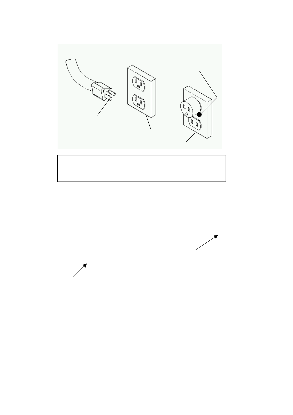
2. Follow all wiring codes and recommended electrical connections. Make certain that
the tool is properly grounded.
3. Make all adjustments with the power “OFF”
4. Always maintain proper adjustment of blade tension, blade guides, and blade
support bearings.
5. Avoid awkward hand positions. A sudden slip could allow the hand to contact the
blade.
6. Do not attempt to saw stock that does not have a flat surface, unless a suitable
support is used.
7. Make sure blade is not contacting the workpiece before turning on the power switch.
8. Always keep hands and fingers away fromthe blade when the machine is running.
9. Hold workpiece firmly against table and feed into blade at a moderate speed.
2

10.Made sure that the saw blade teeth point downward toward the table.
11.Adjust upper guide to just clear work piece.
12.Disconnect machine from the power source when making repairs.
13.Replace all guards after servicing.
14.Turn off band saw if the material is to be backed out of an uncompleted cut.
15.Make relief cuts before cutting long curves.
16.Do not cut material that is too small to be safely supported.
17.Support long heavy work from the floor.
18.Before leaving the machine, make sure the work area is clean.
19.Important: When the tool is not in use , the switch should be in the “OFF” position
and the power cord disconnected.
20.Do not remove jammed cutoff pieces until blade has stopped.
GROUNDING INSTRUCTIONS
1. All grounded, cord-connected tools:
In the event of a malfunction or breakdown, grounding provides a path of least resistance for
electric current to reduce the risk of electric shock. This tool is equipped with an electric cord
having an equipment-grounding conductor and a grounding plug.
The plug must be plugged into a matching outlet that is properly installed and grounded in
accordance with all local codes and ordinances.
Do not modify the plug provided – if it will not fit the outlet, have the proper outlet installed by
a qualified electrician.
Improper connection of the equipment-grounding conductor can result In a risk of electric shock.
3

The conductor with insulation having an outer surface that is green with or without yellow stripes
is the equipment-grounding conductor. If repair or replacement of the electric cord or plug is
necessary, do not connect the equipment-grounding conductor to a live terminal.
Check with a qualified electrician or service personnel if the grounding instructions are not
completely understood, or if in doubt as to whether the tool is properly grounded.
Use only 3-wire extension cords that have 3-prong grounding plugs and 3-pole receptacles that
accept the tool’s plug.
Repair or replace damaged or worn cord immediately.
2. Grounded, cord-connected tools intended for use on a supply circuit having a nominal rating less
than 150 volts:
This tool is intended for use on a circuit that has an outlet that looks like the one illustrated in
Sketch Ain Figure 1. The tool has a grounding plug that looks like the plug illustrated in Sketch A
in Figure 1. Atemporary adapter, which looks like the adapter illustrated in Sketches B and C, may
be used to connect this plug to a 2-pole receptacle as shown in Sketch B if a properly grounded
outlet is not available. The temporary adapter should be used only until a properly grounded outlet
can be installed by a qualified electrician. The green-colored rigid ear, lug, and the like, extending
from the adapter must be connected to a permanent ground such as a properly grounded outlet box.
3. Grounded, cord-connected tools intended for use on a supply circuit having a
nominal rating between 150-250 volts, inclusive:
This tool is intended for use on a circuit that has an outlet that looks like the one illustrated in
Sketch D in Figure 1. The tool has a grounding plug that looks like the plug illustrated in Sketch D
in Figure 1. Make sure the tool is connected to an outlet having the same configuration as the plug.
No adapter is available or should be used with this tool. If the tool must be reconnected for use on
a different type of electric circuit, the reconnection should be made by qualified service personnel;
and after reconnection, the tool should comply with all local codes and ordinances.
4

FIGURE 1
Grounding methods
(B)
(A)
METAL SCREW
COVER OF GROUNDED
OUTLET BOX
GROUNDING
PIN
N
ote : In Canada, the use of a temporary adaptor is not
p
ermitted by the Canadian Electrical Code.
GROUNDING
PIN
GROUNDING
MEANS
ADAPTER
(
D
)
(C)
Table1
Minimum gage for cord
5

Volta Total length of cord in feet
Ampere Rating
120V
240V
25ft. 50ft. 100ft. 150ft.
50ft. 100ft. 200ft. 300ft.
Not
More More
Than Than AWG
0 6
6 10
10 12
12 16
18 16 16 14
18 16 14 12
16 16 14 12
14 12 Not Recommended
6

7
A
B
C
D
E
F
G
H
J
I

Quick release / blade tensioning
Lifting the quick release handle to release blade tension.
Remove blade and replace with new one. Turn down
the handle to tighten blade.
Turn the handle clockwise to minor tighten blade
tension and counterclockwise to release blade tension.
A blade under tension may also pull drive wheel out of
alignment. Adjust alignment of drive wheel with
tracking knob.
Adjusting upper blade support
The blade support bearing (A) should be adjusted so
it almost touches the back of the saw blade when the
blade is tracking properly. To adjust, loosen indexable
locking lever (B) and slide bracket in or out until the
adjustment is correct. Tighten lever. The blade guide
bearing (C) should be adjusted so they almost touch
the slide of the blade. The front edge of the guide
bearings must be positioned just behind the “gullets”
of the saw teeth. To adjust, loosen indexable locking
lever (D) and slide bearing assembly in or out until
the adjustment is correct. Tighten lever. Replace blade
guard.
8

Adjusting lower blade support bearing
The lower bearing adjustments are similar to the
upper bearing adjustments. The blade support
bearing (A) should be adjusted so it almost touches
the back of the saw blade. To adjust, loosen hex
screw (B) and slide bracket in or out until the
adjustment is correct. Tighten screw. The blade
guide bearings (C) should be adjusted so they
almost touch the sides of the blade. To adjust,
loosen hex screw (D) and slide bearing assembly in
or out until the adjustment is correct. Tighten hex
screw.
9

10
An adjustable table stop allows the table to easily return
to 90˚ after tilting.
To set the table stop so the table is 90˚ to the blade,
do these steps:
1. Make sure the blade is correctly tensioned as
described in the Blade Tensioning.
2. DISCONNECT BANDSAW FROM POWER!
3. Loosen the two table trunnion knobs.
4. Loosen the hex nut that locks the table stop bolt in
place.
5. Raise the upper blade guide assembly and place a 6"
machinist’s square or try-square on the table next to
the side of the blade as illustrated inFigure 1.
Adjust the table stop bolt to raise or lower the table
until the table is 90˚ to the blade.
6. Secure the knobs and lock the table stop bolt by
tightening the hex nut against the casting. Ensure
that the bolt does not turn by holding it with anoth-
er wrench while tightening the hex nut.
Table Stop Adjustment
Blade
Table
Square
Figure 1. Squaring table to blade.
The pointer on the table tilt scale (Figure 2) must be
calibrated in order for the scale reading to be accurate.
To calibrate the pointer on the table tilt scale, do
these steps:
1. Make sure the blade is tensioned/tracking correctly
and that the table is 90˚ to the blade (this proce-
dure should be already completed with the Table
Stop Adjustment instructions).
2. Loosen the pointer screw.
3. Align the tip of the pointer with the 0˚ mark on the
table tilt scale.
4. Tighten the pointer screw.
Table Tilt Scale
Calibration
Figure 2. Table tilt scale.
Pointer

11
To ensure cutting accuracy when the table is first
installed, align the table so the miter slot is parallel to
the bandsaw blade. This procedure works best with the
largest blade that the machine accepts.
To align the miter slot parallel to the bandsaw blade,
do these steps:
1. Make sure the blade is correctly tracked and ten-
sioned.
2. DISCONNECT BANDSAW FROM POWER!
3. Loosen the trunnion bolts that secure the trunnions
to the table.
4. Place an accurate straightedge along the blade. The
straightedge should lightly touch both the front and
back of the blade (the flat part only) without touch-
ing the blade teeth.
5. Use a fine ruler to gauge the distance between the
straightedge and the miter slot. The distance you
measure should be the same at both the front and
back ends of the miter slot, as indicated by positions
"A" and "B" in Figure 3.
6. Adjust the table until the distance between the
blade and miter slot is equal at both ends.
7. Tighten the trunnion bolts.
Table Alignment
A
B
Miter Slot
Parallel
with Blade
when A = B
Straightedge
Figure 3. Checking if miter slot is
parallel to blade.
To align the fence parallel with the miter slot, do these
steps:
1. Mount the fence on the right-hand side of the blade,
at the edge of the miter slot, then lock it in place.
2. Loosen the two cap screws that mount the front rail
brackets to the table.
3. Shim between the front rail brackets and table to
make the fence parallel with the miter slot.
Tip: Shim stock works well for this, but small pieces
of paper can also work in a pinch.
4. Tighten the front rail mounting bolts.
Fence Alignment
NOTICE
Adjusting the fence parallel to the
miter slot does not guarantee straight
cuts. The miter slot may need to be
adjusted parallel to the blade. Refer to
the Table Alignment instructions.

12
Blade Changes
To replace the blade, do these steps:
1. DISCONNECT BANDSAW FROM POWER!
2. Release the tension lever.
3. Remove the table insert and the table pin. Adjust
the upper and lower guide blocks away from the
blade.
4. Open the upper and lower wheel covers and slide
the blade off both wheels.
5. Rotate the blade 90˚ and slide it through the slot in
the table.
6. Slide the new blade through the table slot, ensuring
that the teeth are pointing down toward the table.
If the teeth will not point downward in any orienta-
tion, the blade is inside-out. Put on heavy gloves,
remove the blade, and twist it rightside-out.
7. Slip the blade through the guides, and mount it over
the upper and lower wheels.
8. Apply tension.
9. Turn the tension knob until proper blade tension has
been reached according to the blade thickness scale
shown in Figure 4.
10. Check and adjust the tracking.
11. Adjust the upper/lower guide blocks and the support
bearings .
12. Close the wheel covers.
13. Replace the table insert and table pin, being sure
not to use excessive force when inserting the table
pin.
Figure 4. Tensioner adjustment.
Tension Scale
Always disconnect power to the
machine when changing blades.
Failure to do this may result in serious
personal injury.
All saw blades are dangerous and may
cause personal injury. To reduce the
risk of being injured, wear leather
gloves when handling saw blades.

13
SERVICE
When wheels are aligned, or coplanar, the bandsaw cuts
straighter, with much less vibration, heat, and blade wear
because the blade is automatically balanced on the
wheel. See Figure 5 to better understand coplanarity.
If your bandsaw develops tracking problems that can't be
fixed by adjusting the upper wheel tracking knobs, then
check the wheel alignment before taking any other steps.
Verifying Upper/Lower Wheels are Coplanar
1. DISCONNECT BANDSAW FROM POWER!
2. With the blade on and properly tensioned, hold
a straightedge or a self-made "coplanarity gauge"
(Figure 5) close to the center of both wheels. Make
sure the straightedge or gauge fully extends across
the wheels as shown in Figure 5.
— If the wheels are coplanar, the straightedge will
evenly touch the top and bottom of both wheels.
— If the wheels are not coplanar, place the straight-
edge on the lower wheel first (ensuring that it
touches both the top and bottom rim), then adjust
the upper wheel tracking knob to make the upper
wheel parallel with the lower wheel.
— If the straightedge does not touch both wheels
evenly, the upper wheel needs to be shimmed or
the lower wheel needs to be adjusted.
Shimming Upper Wheel
1. DISCONNECT BANDSAW FROM POWER!
2. Make sure the top wheel is adjusted parallel with
the bottom wheel.
3. With the straightedge touching both points of the
wheel that does not need to be adjusted, measure
the distance away from the incorrect wheel with a
fine ruler (see Figure 6).
4. Remove the blade from the saw, then remove the
wheel that needs to be shimmed.
5. Determine how many shim washers you need to com-
pensate for the distance measured in Step 3 and
place them on the wheel shaft.
6. Replace the wheel, the original washers, and the
securing nut.
Wheel Alignment
Figure 6. Measuring wheel difference.
Coplanar Parallel, Not
Coplanar
Not Parallel
Not Coplanar
Adjust
Tracking Knob
Gauge
Contacts Top
And Bottom of
Both Wheels
Coplanarity Gauge
Figure 5. Coplanar diagram.

14
7. Tighten the blade, then check the wheels. (Coplanar
wheels may pull out of alignment when the blade is
tightened.)
8. When the wheels are coplanar, place a mark on each
wheel where you held the straightedge. This assures
repeated accuracy every time you adjust your
wheels.
Note: When wheels are properly coplanar, the blade
may not be centered on the crown of the wheel, but
it will be balanced.
Adjusting Lower Wheel
Only do this procedure if you cannot make the wheels
coplanar with the tracking knob or by shimming the upper
wheel. Make sure the upper wheel is adjusted as close as
possible to being coplanar with the lower wheel before
beginning. Do this procedure with the blade fully ten-
sioned.
To adjust the lower wheel, do these steps:
1. DISCONNECT BANDSAW FROM POWER!
2. Loosen the four hex bolts on the lower wheel
adjust-ment hub (Figure 7).
3. Rotate the wheel adjustment sleeves to tilt the
lower wheel as necessary to make it coplanar with
the upper wheel.
4. Tighten the hex bolts to lock the wheel adjustment
sleeves in position. Figure 7. Wheel adjustment hub.
Wheel
Adjustment
Sleeve
Hex Bolt

INSTALL
1. 5.
2. 6.
3. 7.
4. 8.
14

9. 13.
10. 14.
11. 15.
12.
15

11
ADJUSTMENTS
ADJUSTING KNOB
TABLE
90 ゚
Shaft for 90°

FENCE BODY
TABLE
AB
To level and adjust the height of the fence, loosen the bolt that hold the mounting brackets
to the table, and raise or lower the front rails along the elongated holes in the mounting
brackets. Level the fence, front and back as needed, and set the spacing between the
bottom of the fence and the table to 1mm (approx.) as shown in image. Then, tighten the
bolt to lock the rails in position

1
POWER SUPPLY REQUIREMENT
Insufficient voltage from factory power source may affect the power output of the motor and
the function of the controller.
It is important to connect this machine to the correct voltage in the factory power source.
Use only an independent power source.
3.7 CONNECT POWER SOURCE WIRES
1. Before connecting the power wires make sure the voltage between the machine and your
factory power source is the same.
2. Take out the electrical cover at the electrical control box outside.
3. Connect the power wires to the plug.
4. The machine must be properly grounded to prevent possible injury from electrical shock.
5. Connect the power wires from machine bed to the electrical control box according
connecter type.
6. Qualified electrical personnel should perform all electrical connections.
Grounding should be based on the local regulations.
Table of contents
Other Magnum Industrial Saw manuals

Magnum Industrial
Magnum Industrial MI-51180 User manual

Magnum Industrial
Magnum Industrial MI-92100 User manual

Magnum Industrial
Magnum Industrial MI-91350 User manual

Magnum Industrial
Magnum Industrial MI-91703 User manual

Magnum Industrial
Magnum Industrial MI-91500 User manual

Magnum Industrial
Magnum Industrial MI-91400 Quick start guide

Magnum Industrial
Magnum Industrial MI-91340 User manual

Magnum Industrial
Magnum Industrial MI-51100A User manual

Magnum Industrial
Magnum Industrial MI-92300 User manual

Magnum Industrial
Magnum Industrial MI-93050 User manual