Magnum Industrial MI-92300 User manual

MODEL NO.: MI-92300
OPERATING MANUAL
START
STOP
ON
OFF

-1-
SAFETY RULES
WARNING: FAILURE TO FOLLOW THESE RULES MAY RESULT IN SERIOUS
PERSONAL INJURY.
1. FOR YOUR OWN SAFETY, READ INSTRUCTION MANUAL BEFORE OPERATING THE
TOOL. Learn the tool’s application and limitations as well as the specic hazards peculiar to it.
2. KEEP GUARDS IN PLACE and in working order.
3. ALWAYS WEAR EYE PROTECTION. Wear safety glasses. Everyday eyeglasses only
have impact resistant lenses; they are not safety glasses. Also use face or dust mask if cutting
operation is dusty. These safety glasses must conform to ANSI Z87.1 requirements.
Note: Approved glasses have Z87 printed or stamped on them.
4. REMOVE ADJUSTING KEYS AND WRENCHES. Form habit of checking to see that keys
and adjusting wrenches are removed from tool before turning it on.
5. KEEP WORK AREA CLEAN. Cluttered areas and benches invite accidents.
6. DON’T USE IN DANGEROUS ENVIRONMENT. Don’t use power tools in damp or wet
locations, or expose them to rain. Keep work area well lighted.
7. KEEP CHILDERN AWAY. All visitors should be kept safe distance from work area.
8. MAKE WORKSHOP KID PROOF with padlocks, master switches, or by removing starter
keys.
9. DON’T FORCE TOOL it will do the job better and safer at the rate for which it was not
designed.
10. USE RIGHT TOOL. Don’t force tool or attachment to do a job for which it was not
designed.
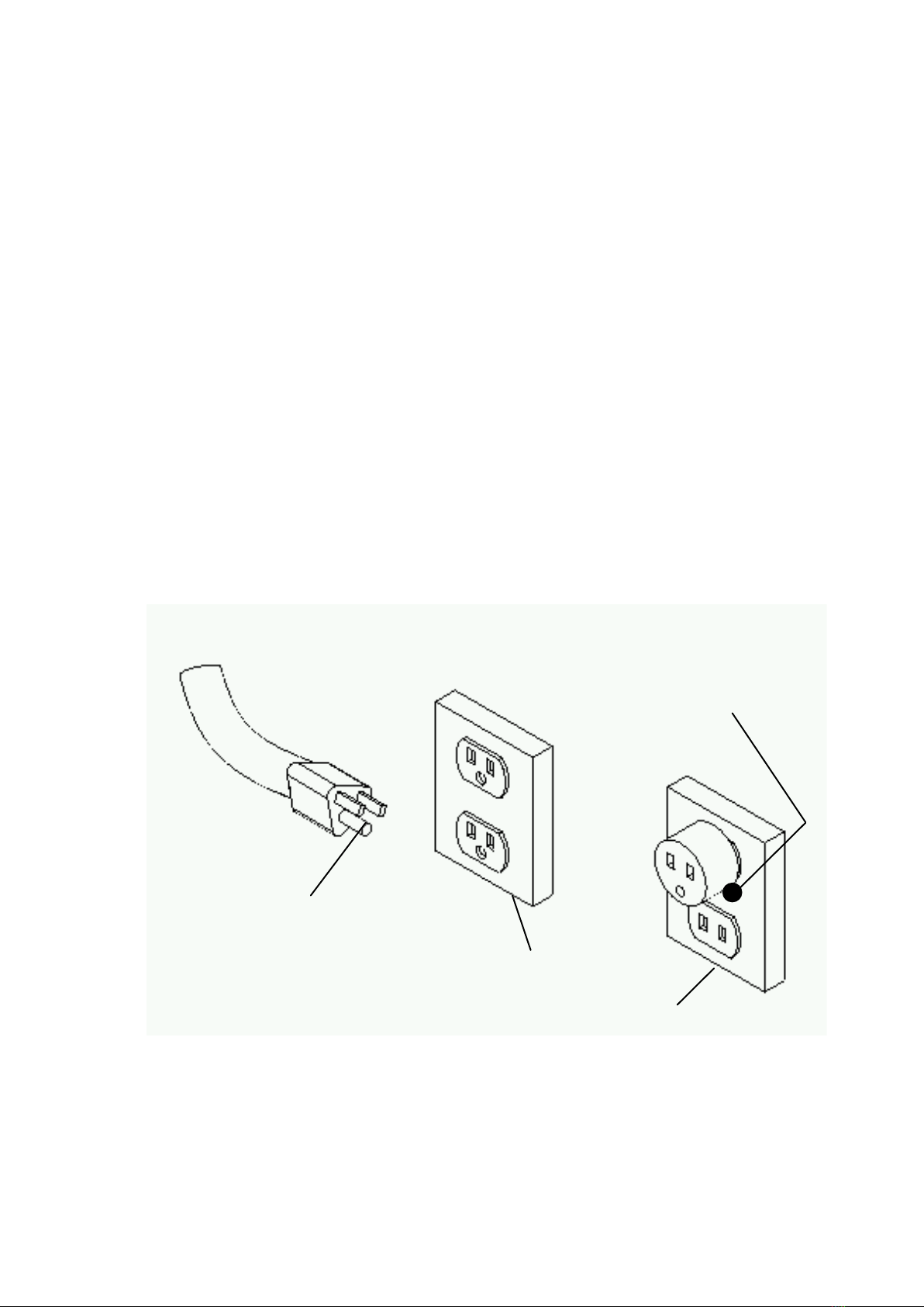
11. USE PROPER EXTENSION CORD. Make sure your extension cord is in good condition.
When using an extension cord, be sure to use one heavy enough to carry the current your
product will draw. An undersized cord will cause a drop in line voltage resulting in loss of
power and overheating. Table 1 shows the correct size to use depending on cord length and
nameplate ampere rating. If in doubt, use the next heavier gage. The smaller the gage number,
the heavier the cord.
12. WEAR PROPER APPAREL Do not wear loose clothing, gloves, neckties, rings, bracelets,
or other jewelry which may get caught in moving parts. Nonslip footwear is recommended.
Wear protective hair covering to contain long hair.
13. ALWAYS USE SAFETY GLASSES. Also use face or dust mask if cutting operation is
dusty. Everyday eyeglasses only have impact resistant lenses, they are NOT safety glasses.
14. SECURE WORK. Use clamps or a vise to hold work when practical. It’s safer than using
your hand and it frees both hands to operate tool.
15. DON’T OVERREACH. Keep proper footing and balance at all times.
16. MAINTAIN TOOLS WITH CARE. Keep tools sharp and clean for best and safest
performance. Follow instructions for lubricating and changing accessories.

-2-
17. DISCONNECT TOOLS before servicing; when changing accessories, such as blades, bits,
cutters, and the like.
18. REDUCE THE RISK OF UNINTENTIONAL STARTING. Make sure switch is in off position
before plugging in.
19. USE RECONNENDED ACCESSORIES. Consult the owner’s manual for recommended
accessories. The use of improper accessories may cause risk of injury or persons.
20. NEVER STAND ON TOOL Serious injury could occur if the tool is tipped or if the cutting tool
is unintentionally contacted.
21. CHECK DAMAGED PARTS. Before further use of the tool, a guard or other part that is
damaged should be carefully checked to determine that it will operate properly and perform its
intended function-check for alignment of moving parts, binding of moving parts, breakage of
parts, mounting, and any other conditions that may affect its operation. A guard or other part that
is damaged should be properly repaired or replaced.
22. DIRECTION OF FEED. Feed work into a blade or cutter against the direction of rotation of
the blade or cutter only.
23. NEVER LEAVE TOOL RUNNING UNATTENDED. TURN POWER OFF. Don’t leave tool until
it comes to a complete stop.
24. MAME SURE TOOL IS DISCONNECTED from power supply while motor is being mounted,
connected or reconnected.
SAVE THESE INSTRUCTIONS
ADDITIONAL SAFETY RULES FOR BAND SAWS
1. If you are not thoroughly familiar with the operation of band saws, obtain advice from your
supervisor, instructor or other qualied person.
2. Follow all wiring codes and recommended electrical connections. Make certain that the tool
is properly grounded.
3. Make all adjustments with the power “OFF”
4. Always maintain proper adjustment of blade tension, blade guides, and blade support
bearings.
5. Avoid awkward hand positions. A sudden slip could allow the hand to contact the blade.
6. Do not attempt to saw stock that does not have a at surface, unless a suitable support is
used.
7. Make sure blade is not contacting the workpiece before turning on the power switch.
8. Always keep hands and ngers away from the blade when the machine is running.
9. Hold workpiece rmly against table and feed into blade at a moderate speed.
10. Made sure that the saw blade teeth point downward toward the table.
11. Adjust upper guide to just clear work piece.

-3-
12. Disconnect machine from the power source when making repairs.
13. Replace all guards after servicing.
14. Turn off band saw if the material is to be backed out of an uncompleted cut.
15. Make relief cuts before cutting long curves.
16. Do not cut material that is too small to be safely supported.
17. Support long heavy work from the oor.
18. Before leaving the machine, make sure the work area is clean.
19. Important: When the tool is not in use , the switch should be in the “OFF” position and the
power cord disconnected.
20. Do not remove jammed cutoff pieces until blade has stopped.
21. ON-OFF SWITCH PADLOCK – To safeguard the band saw from unauthorized operation
and to avoid accidental starting by children or other not qualied to use, the use of padlock is
required. To lock out the on – off switch, open the padlock, insert through the hole of the switch
on button and close the padlock. Place the key in a location that is inaccessible to children and
other not qualied to use the tool.
22. SWITCH WITH KEY – The switch key must be inserted into the switch before saw can
operate. To lock the switch in the OFF position, remove the switch key from the switch. Place the
key in a location that is inaccessible to children and others not qualied to use the tool.
GROUNDING INSTRUCTIONS
1. All grounded, cord-connected tools:
In the event of a malfunction or breakdown, grounding provides a path of least resistance for
electric current to reduce the risk of electric shock. This tool is equipped with an electric cord
having an equipment-grounding conductor and a grounding plug.
The plug must be plugged into a matching outlet that is properly installed and grounded in
accordance with all local codes and ordinances.
Do not modify the plug provided – if it will not t the outlet, have the proper outlet installed by a
qualied electrician.
Improper connection of the equipment-grounding conductor can result In a risk of electric shock.
The conductor with insulation having an outer surface that is green with or without yellow stripes
is the equipment-grounding conductor. If repair or replacement of the electric cord or plug is
necessary, do not connect the equipment-grounding conductor to a live terminal.
Check with a qualified electrician or service personnel if the grounding instructions are not
completely understood, or if in doubt as to whether the tool is properly grounded.
Use only 3-wire extension cords that have 3-prong grounding plugs and 3-pole receptacles that
accept the tool’s plug.
Repair or replace damaged or worn cord immediately.

-4-
2. Grounded, cord-connected tools intended for use on a supply circuit having a nominal rating
less than 150 volts:
This tool is intended for use on a circuit that has an outlet that looks like the one illustrated in
Sketch A in Figure 1. The tool has a grounding plug that looks like the plug illustrated in Sketch
A in Figure 1. A temporary adapter, which looks like the adapter illustrated in Sketches B and
C, may be used to connect this plug to a 2-pole receptacle as shown in Sketch B if a properly
grounded outlet is not available. The temporary adapter should be used only until a properly
grounded outlet can be installed by a qualified electrician. The green-colored rigid ear, lug,
and the like, extending from the adapter must be connected to a permanent ground such as a
properly grounded outlet box.
3. Grounded, cord-connected tools intended for use on a supply circuit having a nominal rating
between 150-250 volts, inclusive:
This tool is intended for use on a circuit that has an outlet that looks like the one illustrated in
Sketch D in Figure 1. The tool has a grounding plug that looks like the plug illustrated in Sketch
D in Figure 1. Make sure the tool is connected to an outlet having the same conguration as the
plug. No adapter is available or should be used with this tool. If the tool must be reconnected for
use on a different type of electric circuit, the reconnection should be made by qualied service
personnel; and after reconnection, the tool should comply with all local codes and ordinances.
Note : In Canada, the use of a temporary adaptor is not
permitted by the Canadian Electrical Code.
GROUNDING
PIN
COVER OF GROUNDED
OUTLET BOX
M ETA L S CR EW
(A)
(B)
FIGURE 1
Gro und ing method s
Note : In Canada, the use of a temporary adaptor is not permitted by the
Canadian Electrical Code.

-5-
ADAPTER
E
ERR
RER
GROUNDING
MEANS
(C)
GROUNDING
PIN
(D)
Ampere Rating
Volta Total length of cord in feet
120V 25ft. 50ft. 100ft. 150ft.
240V 50ft. 100ft. 200ft. 300ft.
Not
More More
Than Than AWG
0 6 18 16 16 14
6 10 18 16 14 12
10 12 16 16 14 12
12 16 14 12 Not Recommended

-6-
K
A
B
C
D
E
F
G
H
I
L
M
J
A: QUICK RELEASE HANDLE H: MITER GUAGE
B: UPPER DOOR KNOBE I: FENCE RAIL
C: GUARD CONTROL HANDWHEEL J: LOWER DOOR KNOBE
D: BLADE GUARD K: ON / OFF SWITCH
E: BLADE THRUST BEARING L: FENCE
F: BEARING GUIDE M: TOOL STORAGE
G: BLADE
START
STOP
ON
OFF

-7-
Quick release / blade tensioning
Lifting the quick release handle to release blade tension. Remove blade and replace with new
one. Turn down the handle to tighten blade.
Turn the handle clockwise to minor tighten blade tension and counterclockwise to release blade
tension.
A blade under tension may also pull drive wheel out of alignment. Adjust alignment of drive wheel
with tracking knob.
Adjusting blade support
Whenever changing a blade or adjusting tension and
tracking, the upper and lower blade support bearings
and guide blocks must be re-adjusted. Always adjust the
assemblies away from the blade before installing a new
blade or making blade tracking adjustments. After blade
tension and tracking are set correctly, re-adjust the upper
and lower support bearings and guide block assemblies into
position. See Figure 8-1 for upper blade guide and Figure 8-2
for lower blade guide.
The support bearings back-up the blade during the sawing
operation. To adjust the support bearings, loosen the screws

-8-
the support bearing shafts. See Figure 8-3. Adjust
the shafts in or out so that the upper and lower
support bearings are within 1/64” of the back edge
of the blade. Retighten the screws.
For optimum support, the guide block assemblies
should be adjusted so they are just behind the
gullet line (the hollow points) of the blade. To
adjust the guide block assemblies, loosen the
screws securing the guide block yoke assemblies.
Move in or out in relation to the blade gullets.
Once adjusted, retighten the screw.
Now adjust the guide blocks. Loosen the guide
block screws and adjust each block so it is about
0.004” from the blade. This is about the same
thickness as a piece of typing paper. Retighten
the screws and turn the upper wheel by hand
through a complete revolution for the blade length
to ensure that the blade weld passes through the
guide blocks unhindered.
INSTALLATION OF FENCE
The image above shows the positioning of the
mounting brackets when properly installed to the table
(front and rear brackets are installed at opposite sides
of the table).
Place the bolts, washers, lock washers and hex
nuts as shown above to attach the mounting
brackets (front and rear) to the table. Don’t tighten
the nuts yet.

-9-
Install a 5/16" screw A , a flat washer B , and a
square nut C on both front mounting brackets.
Install a 5/16" x 5/8" lock knob A and a square nut B on
both rear mounting brackets.
Insert the square nut A of the first front mounting
bracket into the T-slot of the front rail B .
Then, slide the rail onto the second square nut A.
Insert the square nut A of the rst rear mounting
bracket into the T-slot of the rear rail B .

-10-
Then, slide the rail up to the second square
nut A.
Position the rails A to the left or right of the
table B , depending upon the ize of your bandsaw
C i.e. the space between the frame of the saw
and the blade (see image left), and your personal
preferences, then tighten the nuts to lock the rails
in position
Position the fence rmly down on top of the front
rail .
With a 3 mm Allen key, unscrew and remove
the screw A that holds the pointer B into the
right pointer’s window C of the fence base.
Make a pencil mark on the rail, in line with the
pointer’s center mark. Then, unlock the fence and
put aside the pointer, screw and fence for now.

-11-
Cut the measuring tape between both zeros A .
Remove the backing strip from the first half of
the measuring tape (the one with the zero on the
left) and carefully install along the rail slot, using
your pencil mark as the zero-point of the tape .
Trim off excess tape B wih a knife or scissors.
Reinstall the fence on the front rail and lock
it down. Then, reinstall the pointer (place
the screw in the middle of the hole to allow
maximum adjustment capacity on the left or right
afterward), and slide the pointer right or left, so
that its center mark is in line with the zero-point
of the tape. Tighten the screw to lock the pointer
in place.
Unlock the guide fence and repeat steps 1 to 5
with the fence to the left of the blade this time,
aligning the center mark of the left pointer with
the zero of the second half of the measuring
tape.
VERTICAL ADJUSTMENT OF THE FENCE 90° TO THE TABLE
Place a machinist square on the table against
the fence (See Step 4 below) and, either by eye
or with a feeler gauge, look for a gap between
the square and the fence (bottom and top) or the
table. If needed, adjust as follows.
With a 5 mm Allen key, loosen the set screw
(without removing it).
Put the fence back on the rails, but do not
engage the locking handle to lock the fence.

-12-
Reposition the square on the table against the fence
as a reference.
With a flat head screwdriver, slowly turn the screw
A (eccentric shaft) on the fence base. This will tilt
the fence slightly, allowing you to eliminate the gap
between the square and either the fence or the
table.
With the fence adjusted 90° to the table, remove it from the rails, turn it up side down and
retighten the set screw to lock the fence in place.
ALIGNMENT OF THE FENCE PARALLEL TO THE MITER
SLOT
To make satisfactory rip cuts, your fence must be aligned perfectly parallel with the miter slot in
the table. Slide the fence over to the T-slot on your saw, as shown in the second diagram. Lock
down the fence handle and make a visual check to verify if the fence is parallel with the T-slot
along its entire length. You can also place a small block of wood, upright into the T-slot and slide
it from front to back checking its distance from the face of the fence.
If the fence is not parallel, it can be adjusted as follows:
Make sure the guide fence is locked on the rails
(locking handle down).
With a 8 mm Allen key, loosen (without removing)
both screws A that attach the fence to the fence
base.

-13-
Manually adjust the fence B , so that it is parallel
with the miter slot C .
Hold the fence in place with one hand and
tighten the rst screw C.
If needed, adjust a little further with the
remaining bit of play, then tighten the second
screw D.

-14-

-15-
PARTS LIST FOR MI-92300
REF DESCRIPTION REF DESCRIPTION
MI-92300-01 BODY MI-92300-46 HEX BOLT 5/ 16"-18 X 1-1/2"
MI-92300-02 BLADE TEN SION HANDLE MI-92300-46-1 HEX NUT 5/ 16"-18
MI-92300-03
TENSION HAND LE WAS HER
MI-92300-46-2 FLAT WAS HER 5/ 16"
MI-92300-04 UPPER WHEEL BRACKET MI-92300-47 ADJUSTING SCREW
MI-92300-05 HEX BOLT M8 -1. 25 X 110 MI-92300-48 BEARING HOUSING
MI-92300-06 UPPER WHEEL SHAFT MI-92300-49 HEX NUT 5/ 8"-11
MI-92300-07 BALL BEARING 6202ZZ MI-92300-50 V-BELT A-41 4L41 0
MI-92300-08 UPPER WHEEL MI-92300-51 SET SCREW 1/4"-20 X 3/8
MI-92300-09 TIRE MI-92300-52 WHEEL PULLEY
MI-92300-10 INT RETAINING RING 35MM MI-92300-53 IDLER PULLEY
MI-92300-11 LOCK NUT 112-20 MI-92300-54 MOTOR PULLEY
MI-92300-12 BLADE 13J' LONG MI-92300-55 V-BELT A-30 4L300
MI-92300-13 WHEEL GUARD HINGE PIN MI-92300-56 EXT RETAINING RING 15MM
MI-92300-14 UPPER WHEEL GUARD MI-92300-57 IDLER PULLEY SHAFT
MI-92300-15 LOWER GUARD MI-92300-58 FLAT WASHER 5/ 8"
MI-92300-16 CAP SCREW 1/ 4-20 X 3/4 MI-92300-59 MOTOR 1.5HP 220V 3-PH
MI-92300-17 HEX NUT 1/ 4-20 MI-92300-59-1
JUNCTION BOX REAR COVER
MI-92300-18 HEX NUT 3/4-1 0 (LH ) MI-92300-59-2
JUNCTION BOX FRON T COVER
MI-92300-19 LOWER WHEEL MI-92300-59-3 PHLP HD SCR 10-24 X 1/ 4"
MI-92300-20 SPACER MI-92300-59-4 3-CIRCUIT TERMINAL BLOCK
MI-92300-21 LOWER WHEEL SHAFT MI-92300-60 FLAT WASHER 3/8"
MI-92300-22 HEX NUT 3/8-1 6 MI-92300-61
SPECIAL SCREW 3/ 8"-1 6 X 1-1 / 4
MI-92300-23 BALL BEARING 6204ZZ MI-92300-62 HEX BOLT 3/ 8"-1 6 X 2-1 /2"
MI-92300-24 KEY 5 X 5 X 25 MI-92300-63 SWITCH COVER
MI-92300-25 HEX NUT M8 -1 .25 MI-92300-64 PHLP HD SCR M4-.7 X 6
MI-92300-26 LOCK WAS HER 1/ 2 MI-92300-65 PHLP HD SCR M3-.5 X 18
MI-92300-27 CORD 4-WIRE 16AWG MI-92300-66 PHLP HD SCR M4-.7 X 18
MI-92300-30 LOCK NUT 112-20 MI-92300-67 PHLP HD SCR 1/ 4"-20 X 1/2"
MI-92300-31 PLATE NUT MI-92300-68 PHLP HD SCR 10-24 X 3/4"
MI-92300-32 BLADE TEN SION POINTER MI-92300-69
CONTROLLER COVER PLAT
E
MI-92300-33 COMPR ESS ION SPR IN G MI-92300-70 HEX NUT 10-24
MI-92300-34 STRAIN RELIEF MI-92300-71 MOTOR INVERTER SW ITCH
MI-92300-35 HEX NUT 5/ 16"-18 MI-92300-72 SPEED DIAL
MI-92300-36 BLADE TRACK ING KNOB MI-92300-73 SW ITCH W/ LARG E STOP
MI-92300-37
POWER CORD 3-WIRE 16AWG
MI-92300-74
INVERTER RHYMEBUS RMG-5 1HP
MI-92300-38 DOOR COVER KNOB MI-92300-75 HEX BOLT 5/ 16"-18 X 1"
MI-92300-39 CAP SCREW 1/ 4"-20 X 3/4 " MI-92300-76 HEX NUT 5/ 16"-18
MI-92300-40 CORD 3-WIRE 16AWG MI-92300-77 BRUS H BASE
MI-92300-41 PIN 6MM MI-92300-78 PHLP HD SCR 10-24 X 1-1/2 "
MI-92300-42 HEX NUT 3/8"-1 6 MI-92300-79 BRUSH
MI-92300-43 HEX BOLT 3/8"-1 6 X 4 MI-92300-80 HEX BOLT 1/ 4"-20 X 1/ 2"
MI-92300-44 COVER MI-92300-81 LOCK WASHER 1/4"
MI-92300-45 HEX NUT 3/4"-1 6 MI-92300-82 FLAT WASHER 1/ 4"


-17-
PARTS LIST FOR MI-92300
REF DESCRIPTION REF DESCRIPTION
MI-92300-101 HEX BOLT 1/ 4-20 X 3/8
MI-92300-136 PHLP HD SCR 10-24 X 1 i2
MI-92300-102 LOCK WASHER 1/ 4
MI-92300-137 CAP SCREW 1/ 4-20 X 1
MI-92300-103 FLAT WASHER 1/ 4
MI-92300-138 REAR RAIL
MI-92300-104 GUIDE BAR COVER
MI-92300-139 TABLE PIN
MI-92300-105
THUMB SCREW 1/ 4-20 X 1 i2
MI-92300-140 GAUGE
MI-92300-106 FENCE SCALE
MI-92300-140-1 MITER GAUG E HANDLE
MI-92300-107 GUIDE BAR
MI-92300-140-2 MITER GAUG E BODY
MI-92300-108 GUIDE BAR BRACKET
MI-92300-140-4 MITER GAUG E POINTER
MI-92300-109 FLAT WASHER 5/ 16
MI-92300-140-5 MITER GAUG E BAR
MI-92300-110 LOCK WASHER 5/ 16
MI-92300-141 TABLE INSERT
MI-92300-111 HEX BOLT 5/ 16-18 X 5/ 8
MI-92300-142 TABLE (19MM T-SLOT)
MI-92300-112 HANDWHEEL SHAFT
MI-92300-143 GUIDE BAR SCALE
MI-92300-113 HANDWHEEL
MI-92300-144 POI NTER PLATE
MI-92300-114 SET SCREW1 / 4-20X 1/ 4
MI-92300-146 HEX BOLT 3/ 8"-1 6 X 2-1 / 2"
MI-92300-115 EXT RETAINING RING 13MM
MI-92300-147 CLAMP SHOE
MI-92300-116 BALL
MI-92300-148 TRUNNION
MI-92300-117 COMPRESSION SPRING
MI-92300-149 HEX BOLT 5/ 16"-18 X 3/4"
MI-92300-119
GUIDE BAR KNOB 5/ 16-18 X 2
MI-92300-150 HEX BOLT 3/ 8"-1 6 X 2
MI-92300-120 GEAR
MI-92300-151 FLAT WASHER 3/ 8
MI-92300-121 EXTENSION TAB LE
MI-92300-152 TAB LE BRACKET
MI-92300-122 FLAT WASHER 5/ 16
MI-92300-153
TAB LE TRUNNION KNOB 3/ 8"-1 6
MI-92300-123 HEX BOLT 5/ 16-18 X 2
MI-92300-154 PHLP HD SCR 10-24 X 1/4"
MI-92300-124 BLADE COVER
MI-92300-155 TAB LE TILT POINTER
MI-92300-125 LOCK LE VER 1/ 4-20 X 3/ 4
MI-92300-156 TAB LE TILT SCALE
MI-92300-126 CAP SCREW 1/ 4-20 X 3/ 4
MI-92300-157 LOWER SUPPORT BRACKET
MI-92300-127 GUIDE POST BRACKET
MI-92300-158
BLADE GUIDE HOLDER BOTTOM
MI-92300-128
SUPPOR T BEAR IN G SHAFT
MI-92300-159 HEX BOLT 1/ 4-20 X 3/ 4"
MI-92300-129 BALL BEARING 6200ZZ
MI-92300-160 RA IL KNOB 5/ 16"-18 X 5/ 8"
MI-92300-130 EXT RETAINING RING 10MM
MI-92300-161 SQUAR E NUT 3/8"-1 6
MI-92300-131 BLADE GUIDE BLOCK
MI-92300-162 FRON T RAIL
MI-92300-132 BLADE GUIDE HOLDER TOP
MI-92300-164 HEX NUT 5/ 16-18
MI-92300-133 CAP SCREW 1/ 4-20 X 1
MI-92300-165 CAP SCREW 1/ 4-20 X 1
MI-92300-134 GUIDE POST
MI-92300-166 L-BRACKET
MI-92300-135 GUIDE HEIGHT POINTER
MI-92300-167 HANDWHEEL HANDLE
MI-92300-168 FLAT WASHER 3/8"-19

-18-
PARTS LIST FOR MI-92300
REF DESCRIPTION REF DESCRIPTION
MI-92300-200 FENCE ASSY MI-92300-209 PIN 6 X 43
MI-92300-201 FENCE BODY MI-92300-210 PLATE
MI-92300-202 CAP SCR EW M10-1 .5 X 25 MI-92300-211 FENCE LOCK HANDLE
MI-92300-203
BUTTON HD CAP SCR M6 -1 X 10
MI-92300-212 HEX NUT M8 -1 .25
MI-92300-204 FENCE BASE MI-92300-213 LOCK MECHANISM
MI-92300-205 SET SCREW 1/ 4-20 X 1/ 4 MI-92300-214 BEARING SHAFT
MI-92300-206 EXT RETAINING RING 10MM MI-92300-215
FENCE SCALE INDICATOR PLATE
MI-92300-207 BALL BEAR IN G 6200ZZ MI-92300-216 CAP SCREW M6 -1 X 10
MI-92300-208 ECCENTRIC SHAFT MI-92300-217 RUNNER

FAULT DISPLAY
Table of contents
Other Magnum Industrial Saw manuals

Magnum Industrial
Magnum Industrial MI-51100A User manual

Magnum Industrial
Magnum Industrial MI-93050 User manual

Magnum Industrial
Magnum Industrial MI-91400 Quick start guide

Magnum Industrial
Magnum Industrial MI-91600 User manual

Magnum Industrial
Magnum Industrial MI-91500 User manual

Magnum Industrial
Magnum Industrial MI-51180 User manual

Magnum Industrial
Magnum Industrial MI-91703 User manual

Magnum Industrial
Magnum Industrial MI-91350 User manual

Magnum Industrial
Magnum Industrial MI-92100 User manual

Magnum Industrial
Magnum Industrial MI-91500 User manual