Magtek ExpressCard 2000 User manual

ExpressCard 2000| Instant Issuance Card Personalization System | Hopper Module Replacement Procedure
Page 2 of 42 (D99875700-30)
Copyright © 2006 - 2017 MagTek, Inc.
Printed in the United States of America
INFORMATION IN THIS PUBLICATION IS SUBJECT TO CHANGE WITHOUT NOTICE AND
MAY CONTAIN TECHNICAL INACCURACIES OR GRAPHICAL DISCREPANCIES. CHANGES
OR IMPROVEMENTS MADE TO THIS PRODUCT WILL BE UPDATED IN THE NEXT
PUBLICATION RELEASE. NO PART OF THIS DOCUMENT MAY BE REPRODUCED OR
TRANSMITTED IN ANY FORM OR BY ANY MEANS, ELECTRONIC OR MECHANICAL, FOR
ANY PURPOSE, WITHOUT THE EXPRESS WRITTEN PERMISSION OF MAGTEK, INC.
MagTek® is a registered trademark of MagTek, Inc.
MagnePrint® is a registered trademark of MagTek, Inc.
Magensa™ is a trademark of MagTek, Inc.
MagneSafe™ is a trademark of MagTek, Inc.
ExpressCard 2000is a trademark of MagTek, Inc.
Microsoft® and Windows® are registered trademarks of Microsoft Corporation.
All other system names and product names are the property of their respective owners.
Table 0.1 - Revisions
Rev Number
Date
Notes
1.01
09/22/2014
Initial release derived from 99875607-5.01-DRAFT
20
01/30/2015
Update preparation steps / hopper transport movement steps
30
03/21/2017
Update and streamline procedure based on design changes;
misc. clarifications and corrections

ExpressCard 2000| Instant Issuance Card Personalization System | Hopper Module Replacement Procedure
Page 3 of 42 (D99875700-30)
SAFETY
This product has been evaluated by multiple safety certification agencies, including
Underwriters Laboratories (UL) and the United States Federal Communications
Commission (FCC Class A and Class B), and is designed to protect both the user and the
device. This document is written specifically to work in conjunction with these safety and
integrity features to protect the user and the device. It is very important to follow all steps
in the product documentation carefully, in the order in which they are described, and at
the recommended times. Failure to do so could result in personal injury, and / or cause
damage to the device, and / or void the product warranty.
The information within this manual has been prepared for use by trained professional
service personnel and is not intended for general use. To maintain the safety and integrity
of the device, follow the procedures described in this manual carefully.
For your personal safety and to prevent damage to the device, disconnect power from the
device before you connect or disconnect any cable, electronic board, or assembly.
SAFETY REQUIREMENTS
Caution
Never do any of the following:
DO NOT use a ground adapter plug to connect equipment to a power socket-outlet that lacks a
ground connection terminal.
DO NOT attempt any maintenance function that is not specifically described in this manual or in
other ExpressCard 2000 instructional documents published by MagTek.
DO NOT remove any of the covers or guards that are fastened with screws. There are no user-
serviceable areas within these covers.
DO NOT override or “cheat” electrical or mechanical interlock devices.
DO NOT use EC2000 supplies or cleaning materials for other than their intended purposes.
DO NOT operate the equipment if you or anyone else have noticed unusual noises or odors.
Consider the following before operating the ExpressCard 2000:
Connect the EC2000 to a properly grounded AC power socket-outlet. If in doubt, have the socket-
outlet checked by a qualified electrician. Improper connection of the device’s grounding conductor
creates a risk of electric shock.
Place the EC2000 on a solid surface that can safely support the device’s weight plus the weight of a
person leaning against it (such as a service technician).
Be careful when moving or relocating the device. Use proper lifting techniques.
Use materials and supplies specifically designed for MagTek devices. Using unsuitable materials
may result in poor performance, and in some cases may be hazardous.

1 - Table of Contents
ExpressCard 2000| Instant Issuance Card Personalization System | Hopper Module Replacement Procedure
Page 4 of 42 (D99875700-30)
Table of Contents
Table of Contents .............................................................................................................................................. 4
1Required Tools, Materials, and Documents ......................................................................................... 5
1.1 Required Tools.................................................................................................................................. 5
1.2 Suggested Tools ............................................................................................................................... 5
1.3 Required Materials........................................................................................................................... 5
1.4 Suggested Materials ........................................................................................................................ 5
1.5 Required Software and Documents .............................................................................................. 5
2Introduction ............................................................................................................................................... 6
3Hopper Module Replacement Procedure ............................................................................................. 7
3.1 How to Prepare the Device for Removing / Re-installing Modules.......................................... 7
3.2 Remove / Re-install the Hopper Module...................................................................................... 8
3.3 How to Calibrate the Hopper Transport Module........................................................................41

1 - Required Tools, Materials, and Documents
ExpressCard 2000| Instant Issuance Card Personalization System | Hopper Module Replacement Procedure
Page 5 of 42 (D99875700-30)
1Required Tools, Materials, and Documents
1.1 Required Tools
Part Number
Quantity
Description
33011008
1 ea.
ASM TOOL KIT,FIELD SERVICE,EC2000
N/A
1 ea.
Diagonal side cutters or wire cutters
1.2 Suggested Tools
Part Number
Quantity
Description
N/A
1 ea.
Flashlight
N/A
1 ea.
Needle nose pliers
N/A
1 ea.
Scissors
1.3 Required Materials
Part Number
Quantity
Description
33070929
1 ea.
ASSEMBLY, REPLACEMENT KIT, HOPPER MODULE, NO
HOPPERS, EC2000
1.4 Suggested Materials
Part Number
Quantity
Description
33011009
1 ea.
ASSEMBLY, FIELD SERVICE KIT, SPARE PARTS STARTER,
EC2000
1.5 Required Software and Documents
MagTek recommends loading the following required software and documents on a USB thumb drive or
service laptop before visiting the customer site.
Part Number
Quantity
Description
D99875600
1 ea.
INSTALLATION AND OPERATION MANUAL, EC2000
D99875607
1 ea.
HARDWARE SERVICE MANUAL, EC2000

2 - Introduction
ExpressCard 2000| Instant Issuance Card Personalization System | Hopper Module Replacement Procedure
Page 6 of 42 (D99875700-30)
2Introduction
This procedure describes how to replace the hopper module in the ExpressCard 2000 (EC2000), and is
based on content in D99875607 ExpressCard 2000 Hardware Service Manual. It assumes the reader
is familiar with basic operation of the ExpressCard 2000’s user and maintenance functions, so many of
the cross-references to deeper “how-to”procedures from that manual have been removed for brevity.
The information in this document is intended for use by trained professional service
personnel only. It is not intended for general use. To maintain the safety and integrity of
the device, it is important to follow the procedures laid out in this document as-written and
in the order provided.
Caution
For your personal safety, and to prevent damage to the device, disconnect power from the
ExpressCard 2000 before you connect or disconnect any cable, electronic board, or
assembly.

3 - Hopper Module Replacement Procedure
ExpressCard 2000| Instant Issuance Card Personalization System | Hopper Module Replacement Procedure
Page 7 of 42 (D99875700-30)
3Hopper Module Replacement Procedure
3.1 How to Prepare the Device for Removing / Re-installing Modules
To prepare the device for removing / re-installing modules, follow these steps in accordance with standard
safety practices:
1) Offer the customer the opportunity to remove any proprietary or security-sensitive consumables from
the device, including card stock, image printer ribbons, indent cartridges, and tipper foils. Some
consumables contain negative imprints of cardholder data and must be handled securely.
2) Make sure you have adequate lighting around the device, and / or plan to use a flashlight.
3) Make sure you have a safe location to place removed parts and replacement parts.
4) Make sure the device is powered up and connected to the network.
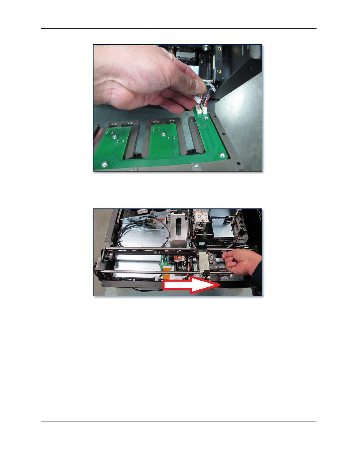
5) Park the hopper transport at the front of the device by following these steps:
a) From the touchscreen, press the Menu button.
b) Press the Maintenance button to open the Maintenance Menu page.
c) Press the Remove Hopper button and wait for the hopper shuttle to finish moving.
6) If the relevant replacement procedure requires you to use the touchscreen user interface, perform
those steps while the device is still powered up and connected to the network.
7) Power down the device.
8) Disconnect the device’s power cable from the AC socket-outlet, then disconnect the power cable and
network cable from the rear of the device.
9) If necessary, unlock or disconnect any security hardware from the device.
10) If the replacement procedure requires you to remove the device’s top access door or the entire cover,
or requires rear access to the device, make sure you have adequate clearance around the device.
Depending on the installation location, you may need to move the device to a service location.

3 - Hopper Module Replacement Procedure
ExpressCard 2000| Instant Issuance Card Personalization System | Hopper Module Replacement Procedure
Page 8 of 42 (D99875700-30)
3.2 Remove / Re-install the Hopper Module
Approximate time to remove: 30 minutes plus any sub-procedures
Approximate time to re-install: 30 minutes plus any sub-procedures
The hopper module holds the device’s card stock hoppers and carries blank card stock to the image
printer from the hoppers or from the manual feed slot. It is mounted to the top deck plate of the device
along the right side.
Figure 3-1 - Hopper Module (FRONT LEFT VIEW FROM ABOVE)
To remove the hopper module, follow these steps:
1) Prepare the device for replacing parts by following the steps in section 3.1 How to Prepare the
Device for Removing / Re-installing Modules. At the end, the device should be powered down with
all external cables safely disconnected and the hopper shuttle parked near the front of the device.
2) Remove the cover (see D99875607 ExpressCard 2000 Hardware Service Manual for details).
3) Remove all the card stock hoppers and set them aside in a secure location, or give them to the
customer for secure temporary storage.

3 - Hopper Module Replacement Procedure
ExpressCard 2000| Instant Issuance Card Personalization System | Hopper Module Replacement Procedure
Page 9 of 42 (D99875700-30)
4) Use the 5/64” hex wrench to remove 5 ea. screw 46500187 that hold the hopper deck plate to the
hopper module.
5) Carefully lift the hopper deck plate off the hopper module, turn it over so you can see printed circuit
board on the bottom, and locate the two sensor cables connected near the rear of the hopper module.
6) Photograph or note the label or color of the two sensor cables so you can reconnect them the same
way when you install the replacement module later.
7) Disconnect the two sensor cables and set the hopper deck plate aside in a safe place with the printed
circuit board facing the floor to protect the sensor flags.

3 - Hopper Module Replacement Procedure
ExpressCard 2000| Instant Issuance Card Personalization System | Hopper Module Replacement Procedure
Page 10 of 42 (D99875700-30)
8) Pull on the hopper shuttle drive belt to move the hopper shuttle toward the rear of the device, past the
connectors on the top deck plate. Do not pull directly on the hopper shuttle or you may damage
it.
9) Use the 5/32” ball end hex wrench to remove the four screws and washers that hold the four corners
of the hopper module to the top deck plate, and set them aside for later use.

3 - Hopper Module Replacement Procedure
ExpressCard 2000| Instant Issuance Card Personalization System | Hopper Module Replacement Procedure
Page 11 of 42 (D99875700-30)
10) Find the belt tension screw on the front of the hopper module. Use the 5/32” hex wrench to loosen
the screw just until the belt is loose enough to slip off the geared pulleys.
11) Slip the hopper shuttle belt completely off the pulley near the rear of the device.

3 - Hopper Module Replacement Procedure
ExpressCard 2000| Instant Issuance Card Personalization System | Hopper Module Replacement Procedure
Page 12 of 42 (D99875700-30)
12) Locate the HOPPER SHUTTLE circuit board mounted to the top deck plate below the center of the
hopper module.
13) Find the HOPPER SHUTTLE EXC HOME SENSOR cable connected to J4 EXC HOME SENS on
the HOPPER SHUTTLE circuit board. Unplug the cable from the circuit board.

3 - Hopper Module Replacement Procedure
ExpressCard 2000| Instant Issuance Card Personalization System | Hopper Module Replacement Procedure
Page 13 of 42 (D99875700-30)
14) Unclip the HOPPER SHUTTLE EXC HOME SENSOR cable from the cable clip on the right side of
the top deck plate.
15) If the HOPPER SHUTTLE EXC HOME SENSOR cable is routed underneath the circuit board,
carefully thread it out and free it. If it is routed underneath other cables, thread it out until it is free all
the way to the front right corner of the device.
16) Unclip the HOPPER SHUTTLE EXC HOME SENSOR cable from the cable clip in the front right
corner of the device’s case, and route it outside the case to keep it out of the way.

3 - Hopper Module Replacement Procedure
ExpressCard 2000| Instant Issuance Card Personalization System | Hopper Module Replacement Procedure
Page 14 of 42 (D99875700-30)
17) Trace the hopper module flex cable to its connector on the hopper shuttle.
18) Disconnect the flex cable from the hopper shuttle. It may require both hands to apply enough force,
because the hopper shuttle obstructs direct access.

3 - Hopper Module Replacement Procedure
ExpressCard 2000| Instant Issuance Card Personalization System | Hopper Module Replacement Procedure
Page 15 of 42 (D99875700-30)
19) VERY carefully pull the flex cable free from the double-sided foam tape just next to the connector.
The flex cable will be reused so it is important to not damage it.
20) Use your fingers to rub all foam tape residue off the connector end of the flex cable.
21) Gently push the hopper shuttle toward the front of the device, past the connectors on the top deck
plate.

3 - Hopper Module Replacement Procedure
ExpressCard 2000| Instant Issuance Card Personalization System | Hopper Module Replacement Procedure
Page 16 of 42 (D99875700-30)
22) Find the HOPPER SHUTTLE HOME SENSOR cable connected to the J3 HOME SENS connector
on the HOPPER SHUTTLE circuit board and disconnect it.
23) Trace the HOPPER SHUTTLE HOME SENSOR cable back to the hopper module and cut any cable
ties holding it.

3 - Hopper Module Replacement Procedure
ExpressCard 2000| Instant Issuance Card Personalization System | Hopper Module Replacement Procedure
Page 17 of 42 (D99875700-30)
24) Carefully unthread the HOPPER SHUTTLE HOME SENSOR cable from its routing path to free it
completely from the device, leaving it connected to the rear of the hopper transport module.
25) Gently push the hopper shuttle to the middle of the device.

3 - Hopper Module Replacement Procedure
ExpressCard 2000| Instant Issuance Card Personalization System | Hopper Module Replacement Procedure
Page 18 of 42 (D99875700-30)
26) Swing the shuttle to retract it above its base.
27) Carefully lift the hopper module out of the device. Tilt it to avoid hitting the pulley at the rear of the
device, lift the front end first, and make sure it doesn’t snag any cables, belts, or other parts on the
way out. Set the hopper module aside.
28) If you are removing the hopper transport gearbox, locate it at the rear of the device.

3 - Hopper Module Replacement Procedure
ExpressCard 2000| Instant Issuance Card Personalization System | Hopper Module Replacement Procedure
Page 19 of 42 (D99875700-30)
29) Use the 5/32” hex wrench to loosen the two screws that hold the hopper module gear box to the top
deck plate. The screw nearer the front of the device is beneath a bundle of cables, which you will
have to move out of the way.
30) Disconnect the gearbox cable from the device.

3 - Hopper Module Replacement Procedure
ExpressCard 2000| Instant Issuance Card Personalization System | Hopper Module Replacement Procedure
Page 20 of 42 (D99875700-30)
31) Remove the hopper gearbox and screws and set them aside.
32) Remove the screws and washers from the hopper gearbox for later use.
Other manuals for ExpressCard 2000
8
Table of contents
Other Magtek Control Unit manuals
Popular Control Unit manuals by other brands

Yamatake-Honeywell
Yamatake-Honeywell 7800 Series Product data

VBG
VBG CONTROL BOX POWER-PNEUMATICS MFC Mounting instruction

DeZurik
DeZurik KSL-SD instructions

National Instruments
National Instruments NI-9361 CALIBRATION PROCEDURE

Honeywell
Honeywell Kromschroder TC 1 operating instructions

Arbor Technology
Arbor Technology EmETX-a55E0 user manual