© MAHLE
8 | OBD-II Smartbox | Product Useen
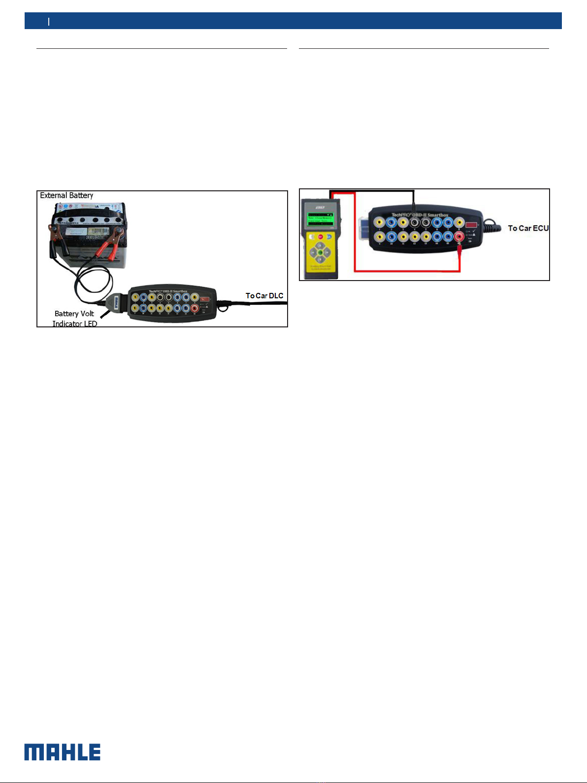
3.3 Detect communication protocol
This method of use is to detect and monitor which type of com-
munication protocol the ECU is using, whether PWM (J1850),
VPW (J1850), ISO 9141-2, DIS/ISO 14230-4 or Can bus (J-2284).
LEDs signals:
OBD-II Smartbox LEDs allows you to keep taps on power and
ground. It identifies the protocol used in the vehicle.
1. RED LEDs (Pin 16) - automatically turn-on as soon as you
plugged into DLC. RED LEDs turn dim when:
— Low battery voltage - refer to Voltmeter and alarm will
beep (below 11.8V for 12V system and 23.8V for 24V
system). Wiring to DLC pin 16 is faulty. Ground circuits
have resistance issues.
2. BLACK LEDs (Pins 4 – Chassis and 5 - Signal) - automatically
turn-on as soon as you plugged into DLC. Ground LED (Pin 5)
is connected to battery voltage via ECU. Therefore, a ground
supply on pin 4 will not affect LED 5. A dim single green LED
will indicate a circuit problem with the corresponding circuit. In
remote case where if there is reverse polarity; the Green LED
will turn into RED color. When this happens, check the vehicle
DLC connector for wrong polarity. Rectify first and test again.
3. BLUE LEDs (Pins 2, 6, 7, 10, 14 and 15) - LEDs should flash
when serial data voltage pulses are present in the data line.
— Blue LEDs is assigned on pins 2, 6, 7, 10, 14 and 15 to
indicate communication with scan tool or interface and
for communication protocol identification. It will turn-on
depend on your vehicle model. For some vehicle model,
one or multiple blue LEDs will turn-on as soon as the
OBD-II Smartbox is connected and you start the igni-
tion. The brightness of the LEDs depends on the nature
of the signal it's pursuing. This OBD-II Smartbox can
identify immediately the protocol used. The better way
to identify the protocol in use is to set-up the scan tool
or interface in to LIVE DATA. This will lead in a constant
data stream between the scan tool and the vehicle, and
then you can locate the LEDs that are flashing.
4. GREY LEDs (Pins 1, 3, 8, 9, 11, 12, and 13) - it should flash
when your vehicle manufacturer use either one on the pins
for any function they prefer.
Pin Assignments
Pin # SAE Designation
1 - Discretionary
2 - Bus + Line of SAE J1850 (PWM/VPW)
3 - Discretionary
4 - Chassis Ground
5 - Signal Ground
6 - CAN High of SAE J2284 (ISO 15765-4)
7 - K Line ( ISO 9141-2 and ISO 14230-4)
8 - Discretionary
9 - Discretionary
10 - Bus-Line of SAE J1850(PWM)
11 - Discretionary
12 - Discretionary
13 - Discretionary
14 - CAN Low of SAE J2284 (ISO 15765-4)
15 - L Line (ISO 9141-2 and ISO 14230-4)
16 - Unswitched Vehicle Battery Positive
Pins listed as "Discretionary" indicate that the vehicle manu-
facturers may used them for specified purpose. Check with the
manufacturer's specifications for these connections. For voltage
and current limits, refer to SAE J1962 (ISO 15031-3.3). Test tool
must not draw more than 1.5 amps through the pin number 5
(Signal ground).
Helpful Tips:
tWhen activating some ABS and diagnostics wires to recover
flash code, you can use pin 4.
tIf red (power) and green (grounds) LEDs turned dim or flicker-
ing when you plugged a scan tool supplied via DLC, it indicate
a problem with your vehicle wiring that causes the voltage
to drop.