|10 |ATJ-1000H
Maintenance and Inspection
8. Maintenance and Inspection
WARNING - The jack must be inspected accordingto
the requirements of this section. Failure to properly
inspect the jack could lead to severe injury or death.
The jack must be removed from service and inspected
immediately if it is subjected to an abnormal load or a
shock load. If any irregularities or problems are
detected during an inspection, the jack must be
removed from service immediately and repaired.
Contact the manufacturer at the numbers and address
printed on the back cover of this manual.
8.1 Inspection – before each use
The jack owner (or a knowledgeable person appointed by
the owner) must give the jack a more thorough inspection
weekly (if it is used on a daily basis) or monthly (if used
less frequently). In addition to a visual inspection (as
described above), the inspector should also operate and
move the jack to assist in identifying any problems that
might exist. The jack must be removed from service and
repaired if the jack appears damaged, if it is badly worn,
or if it operates abnormally.
Visual inspection of the jack must be made before each
use of the jack. The jack should be immediately removed
fromservice ifanyofthe followingconditions are detected
or observed:
Visually inspect the jack for signs of cracking,
chipping, or excessive wear, including all welds.
Visually inspect all four casters for cracking, chipping
or excessive wear.
Visually inspect the power unit for oil leaks.
Any abnormal condition or sign of damage that
suggests the jack will not work properly.
If any irregularities or problems are detected during an
inspection or during operation, the unit must be
removed from service immediately and repaired.
Contact the manufacturer using the contact
information on the back cover of this manual.
8.2 Maintenance instructions
WARNING - All inspection and maintenance procedures
must be performed after the jack has been removed from
service. Failure to do this may result in personal injury
and/or property damage.
Lower unit completely and exhaust all air from the air
cylinder before servicing the air cylinder. Failure to
exhaust all air from the air cylinder can cause rapid
separation of the piston rod from the air cylinder.
Failure to heed this warning may result in serious
personal injury and / or property damage.
Apply light machine oil at all portions of movement to
the jack monthly.
All warning and capacitylabels should be readable and
complete. Wash external surfaces of jack, labels, and
decals with a mild soap solution.
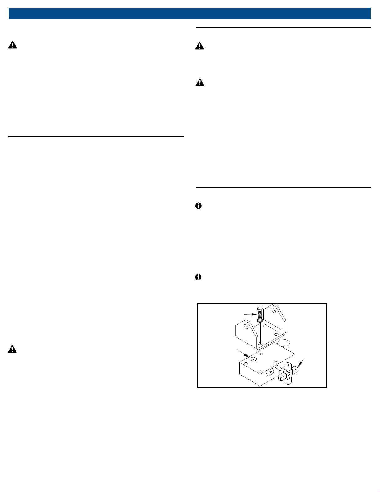
8.3 Replenish oil supply
With all four casters of the jack resting on the floor,
lower the hydraulic stage fully and remove the head
assembly by extracting the four head mounting bolts.
See Fig. 6. Carefullyclean the top of the jackto remove
all dirt, especially in the vicinity of the fill plug. Remove
the release knob by turningcounterclockwise. Remove
the fill plug and using a squirt-oil can, slowly add Tellus
T22 oil (or equivalent) until reservoir overflows.
Note: The release knobopeningserves asreservoirvent
during filling. Be sure to reinstall release knob and fill
plug, and then remount the head assembly.
Fig. 6: Replenish oil
Fill Plug Release
Knob
Head Mounting
Bolts