Makerfarm Pegasus 12 User manual

Updated 6/19/17

2
Maker Farm Inc. Limited Warranty
1. Limited Warranty. Maker Farm Inc. (“MFI”) warrants to the original purchaser (the “Customer”) that the products purchased by Customer
from MFI (the “Products”) are free from defects in material and workmanship for a period of thirty (30) days from the date of shipment to
Customer for Products, unless otherwise specified by MFI. MFI will accept returns of any non-clearance, unopened, unused and unassembled
item ordered directly from www.Makerfarm.com, after the warranty your purchase is final and no returns will be accepted. MFI charges a
restocking fee of 20% of the purchase price (price of product, excluding tax and shipping), and in addition the buyer must pay all shipping
charges (shipping charges on the initial purchase is not refundable). Once a kit has left our shop there is no way for us to know how it was
handled. Therefore, only unopened, unbuilt, kits that have no evidence of an attempted build or use will be refunded less the 20% restock fee.
Things like opened/unsealed plastic bags, any marks on the components, etc. Will result in no refund given on the kit. Should you purchase a
kit and begin to assemble it, you will not be able to return that kit for a refund.
2. MFI’s Obligation. The sole obligation of MFI, at its option and without charge, is to repair, replace, or refund the original purchase price paid
by Customer for, any Product or part, which MFI manufactures and which MFI agrees is defective. Repair parts or replacement Products may be
new, remanufactured, or refurbished, at the sole discretion of MFI. All returned parts or Products that are replaced become the property of MFI.
3. Transfer of Other Warranties. In the case of equipment and accessories not manufactured by MFI, if a warranty is extended by the
manufacturers thereof and transferable to Customer, MFI shall transfer such warranty to Customer.
4. Exclusions. MFI’s limited warranty provided herein does not cover: (i) normal wear and tear; (ii) transport damage; (iii) failure to follow
operation or maintenance instructions; (iv) Customer’s negligent modification (including painting or staining wood pieces), disassembly or
attempted repairs of the Product; (v) abuse, misuse or negligent acts; (vi) accidental or intentional damage; or (vii) cosmetic shortcomings which
do not influence Product function.
5. Disclaimers. unless expressly set forth in this limited warranty, MFI makes no warranty of any kind whatsoever, express or implied, with
respect to any products furnished hereunder. MFI expressly disclaims, where legally permitted to make such disclaimer, any warranties implied
by law, including but not limited to any warranty of merchantability or fitness for a particular purpose.
6. Limitation of Damages. IN NO EVENT SHALL MFI BE LIABLE TO CUSTOMER FOR ANY INDIRECT, CONSEQUENTIAL,
PUNITIVE, EXEMPLARY, INCIDENTAL OR SPECIAL DAMAGES, OR ANY DAMAGES WHATSOEVER RESULTING FROM LOSS
OF USE, PROFITS, OR DOWN-TIME (HOWEVER CAUSED AND UNDER ANY THEORY OF LIABILITY, WHETHER THE BASIS OF
LIABILITY IS BREACH OF CONTRACT, TORT (INCLUDING NEGLIGENCE AND STRICT LIABILITY), STATUTE OR ANY OTHER
LEGAL THEORY), EVEN IF MFI HAS BEEN ADVISED OF THE POSSIBLITY OF SUCH DAMAGES. MFI’S TOTAL LIABLITY TO
CUSTOMER, FROM ALL CAUSES OF ACTION AND UNDER ALL THEORIES OF LIABILITY, WILL BE LIMITED TO THE
AMOUNTS PAID TO MFI BY CUSTOMER. THESE LIMITATIONS SHALL APPLY NOTWITHSTANDING ANY FAILURE OF
ESSENTIAL PURPOSE OF ANY LIMITED REMEDY. THE REMEDIES UNDER THIS LIMITED WARRANTY ARE CUSTOMER’S
SOLE AND EXCLUSIVE REMEDIES.
7. Return Merchandise Authorization (RMA) Process for Defective Products.
7.1 A Return Merchandize Authorization (“RMA”) number must be obtained from MFI before Customer can return any Product to
MFI for warranty service. An MFI representative will gather the appropriate account and Product information and verify warranty status. MFI
must receive notification of the need for warranty service before the end of the applicable limited warranty period. The RMA number must be
included on the outside packaging of the returned Product. To obtain an RMA number, please contact MFI by email as follows:
7.2 Any approved RMA should be considered provisional, based on verification of in-warranty status when the Product is received at
MFI. If MFI determines that the Product is out-of-warranty, Customer will be notified. At the Customer’s discretion, MFI will either scrap the
out-of-warranty Product or return it to Customer.
7.3 Customer is responsible for all shipping charges for RMAs to MFI, and MFI is responsible for all shipping charges to return the
Product or its replacement to the Customer. Standard Shipping is used to return products to Customers.
7.4 MFI will typically not decide whether to repair, replace, or refund the purchase price for, any returned Product until the returned
Product is received at MFI and the warranty status is confirmed.
7.5 Under special circumstances, if the Customer would like to expedite the RMA process, MFI may agree from time to time to cross-
ship a replacement Product after the issuance of an RMA number but before receipt of the returned Product, but MFI shall not be obligated to do
so. Cross-ship orders require a valid credit card number or credit account to secure the MFI Product. The Customer’s credit card or credit
account will be credited if MFI receives the returned Product within fifteen (15) days of the date on which MFI ships the replacement Product,
and provided further that the returned Product was in-warranty.
8. Discontinuance of Products. Notwithstanding any language in this limited warranty to the contrary, MFI shall have the right to discontinue
the availability of any Product or components or replacement parts therefor, or to make design changes or improvements in the Products at any
time and such discontinuance or change shall not constitute a breach of warranty, or result in liability for MFI under any legal theory
whatsoever. MFI shall have no obligation to retrofit, change or improve Products purchased by Customer prior to the discontinuance or change.
9. Other Rights. This limited warranty gives you specific legal rights, and you may also have other rights which vary from State to State, and
from Country to Country.
9.1 EXCEPT TO THE EXTENT LAWFULLY PERMITTED, THIS LIMITED WARRANTY DOES NOT EXCLUDE, RESTICT OR
MODIFY STATUTORY RIGHTS APPLICABLE TO WHERE THE PRODUCT IS SOLD, BUT RATHER IS IN ADDITION TO THESE
RIGHTS.

3
Pg 2: Warranty information
Pg 4: Information on Power Supply, Glass and Filament
Pgs 5-6: Identification
Pg 7: Frame
Pgs 8-14 : Y,Z Motor & Y Extrusion
Pgs 15-23: Y Bed
Pgs 24-27: Metal X Motor Assembly
Pgs 28-30: Metal X Idler Assembly
Pgs 31-33 : X Carriage
Pgs 34-40 : X Axis
Pgs 41-43 : Belts
Pgs 44-46: Heat Bed
Pgs 47-48: Endstops
Pgs 49-52: LCD Installation
Pg 53: E3D Hot End Assembly
Pgs 54: Extruder Assembly
Pgs 55-57: Z Rods
Pgs 58-65: RAMPS Install / Wiring Diagram
Pgs 66-72: Wiring your Power supply
Pgs 73-76: Software/Firmware/First Prints
Pg 77: Wire Management
Pgs 78-80: Pronterface
Troubleshooting Guide: Download

4
Pegasus 12”
This Guide has Hyper links so is not recommended to print the guide. To use the guide click
File then Download and open the PDF in your PDF Viewer, if you view the Guide online the
Hyper links will not function
Thank you for purchasing the Pegasus 12” Kit. To complete your build you will need a
couple other items, Piece of Glass, Power Supply, Insulation and Hairspray:
Piece of Glass: 12”x12” then break the corners off to avoid hitting the bolt heads (3/16” or
5mm Thick Minimum if your heat bed relay is built into the Heat bed or 3.5mm thick if you
have a separate heat bed relay). Most hardware stores will cut it to the size you need, Inside
the USA Lowes or Home Depot
For the Power Supply, Insulation and Hairspray see the links at the bottom of the 12”
Pegasus Page here: http://www.makerfarm.com/index.php/3d-printer-kits/12-pegasus-
kit.html
You may also want some filament to print with after you have built your printer.
Makerfarm.com does sell filament and we would recommend using our filament or another
high quality manufacturer. If you want to purchase your filament somewhere else make sure
you get high quality filament, poor quality filament (Amazon and eBay) will jam and cause
problems.
While your printer is on you should always be by your printer, do not leave it unattended
At any time if you have any questions feel free to e-mail or chat via google chat:
elderfarrer@gmail.com
Thanks,
Colin Farrer—Sales@MakerFarm.com
5

6

There are two different hardware kits for the Frame. Follow the guide
for your version by clicking on the
link below, after you finish that
guide come back to this build
guide to finish your build.
Frame Kit Version 1 has 10 Cast
Corner Brackets with Nubs, 4 Cast
Corner Brackets without Nubs and
32 Hidden Corner Brackets.
FRAME KIT VERSION 1 Build
Guide
Frame Kit Version 2 has
one kit with 35 Cast Corner
Brackets with Nubs, 4 Cast
Corner Brackets without
Nubs and 7 Hidden Corner
Brackets.
FRAME KIT VERSION
2 Build Guide
8
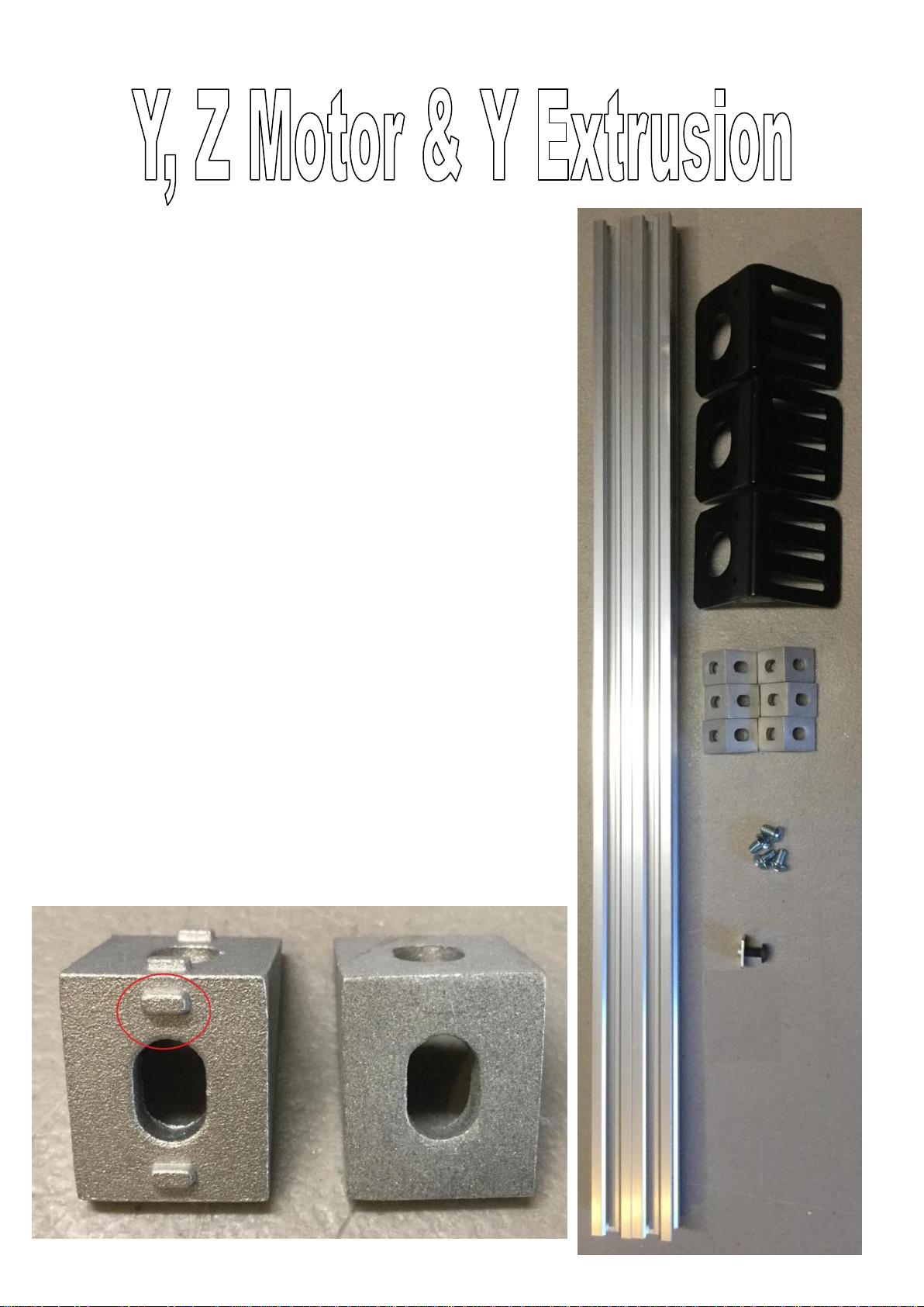
Gather the following parts if your kit came with 14 of
the 20x40 extrusions then follow pages 9, 10, 11
2 20x20mmAluminum Extrusions
2 x Cast Corner Brackets with Nubs if you have
any left (Shown by the red circle in the photo below,
if none of your brackets have nubs then use 2 without
nubs)
4 x Cast Corner Brackets without Nubs
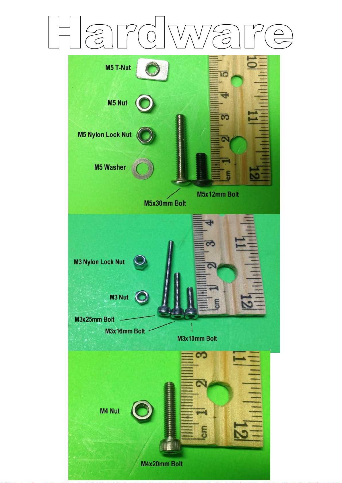
4 x M5x8mm Bolts
3 x Motor Mounts
1 x M5x12mm Bolt
1 x T-Slot Nut
If you have 16 20x40 extrusions instead of 14 the
following then follow pages 12, 13 and 14
2 20x40mmAluminum Extrusions
8 x Cast Corner Brackets without Nubs
2 x Cast Corner Brackets with Nubs
(Shown by the red circle in the photo below, if none
of your brackets have nubs then use 2 without nubs)
8 x M5x8mm Bolts
3 x Motor Mounts
1 x M5x12mm Bolt

9
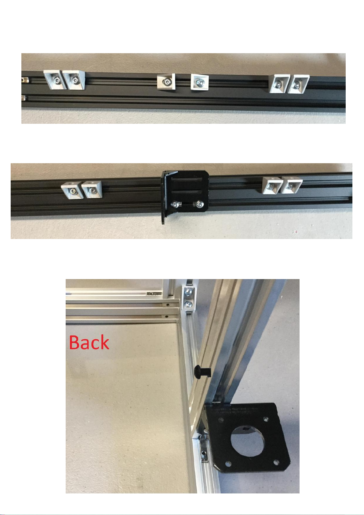
Install 4 Cast Corner Brackets on the bottom front of the machine using the M5x8mm
bolts installed previously (Use the ones with Nubs if you havent already installed them
them in the position with a Red Circle). You will adjust the actually placement later.
Now install 2 Cast Corner Brackets without Nubs and one Motor Mount on the bottom
back of the frame using the previously installed M5x8mm Bolts. You will adjust the
actually placement later.
Now Install a Motor Mount of the right side of the printer, make sure you use the slot
on the far left of the motor bracket.

10
Now Install a Motor Mount of the left side of the printer, make sure you use the slot on
the far left of the motor bracket.
Next using the Extrusion and M5 bolts install the extrusion into the cast corner
brackets. Also install the M5x12mm bolt and T-Slot nut onto the right extrusion.

11
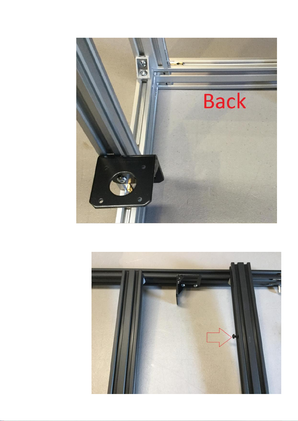
Connect the extrusion to the Cast Corner Brackets in the front of the machine also.
Make sure the bottom of the Extrusion is aligned with the bottom of the cast corner
bracket on all 4 brackets otherwise yourY axis will not be flat.
12
Install 6 Cast Corner Brackets on the bottom front of the machine using the M5x8mm
bolts installed previously. You will adjust the actually placement later.
Now install 4 Cast Corner Brackets and one Motor Mount on the bottom back of the
frame using the previously installed M5x8mm Bolts. You will adjust the actually
placement later.
Now Install a Motor Mount of the right side of the printer, make sure you use the slot
on the far left of the motor bracket.
13
Now Install a Motor Mount of the left side of the printer, make sure you use the slot on
the far left of the
motor bracket.
Next using the
Extrusion, M5 bolts
and T-Slot nuts install
the extrusion into the
cast corner brackets.
Also install the
M5x12mm bolt and T-
Slot nut onto the right
extrusion (Shown by
red arrow).
14
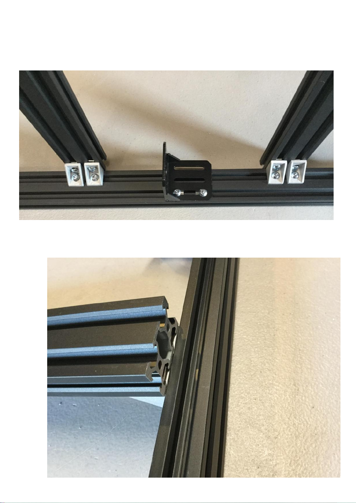
Connect the extrusion to the Cast Corner Brackets in the front of the machine also.
This picture will show how the underside of the extrusion will look.
Make sure the bottom of the Extrusion is aligned with the top of the front and back
extrusion pieces otherwise yourY axis will not be flat.
15
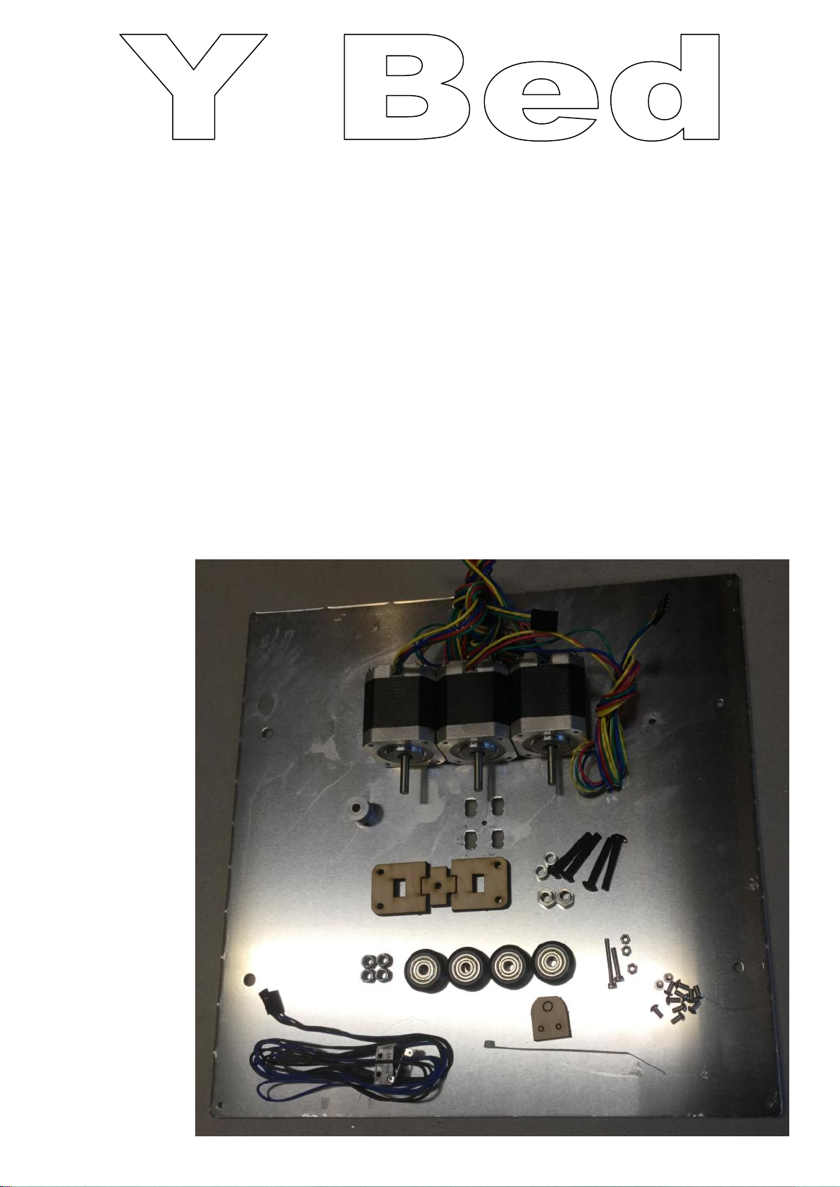
Gather the following parts
1 x Aluminum Heat Bed Mount
3 x Motors
1 x GT2 Gear and Set Screws
1 set of wood Y belt Mount
2 x Aluminum Spacers
2 x Eccentric Spacers
4 x M5x30mm Bolts
4 x M5 Nylon Lock Nut
4 x Delrin Idlers
1 x M3x25mm bolt
1 x M3x16mm bolt
3 x M3 Nylon Lock Nut
1 x Endstop
1 x Zip Tie
1 x Wood Endstop Mount
12 x M3x6mm Bolts
16
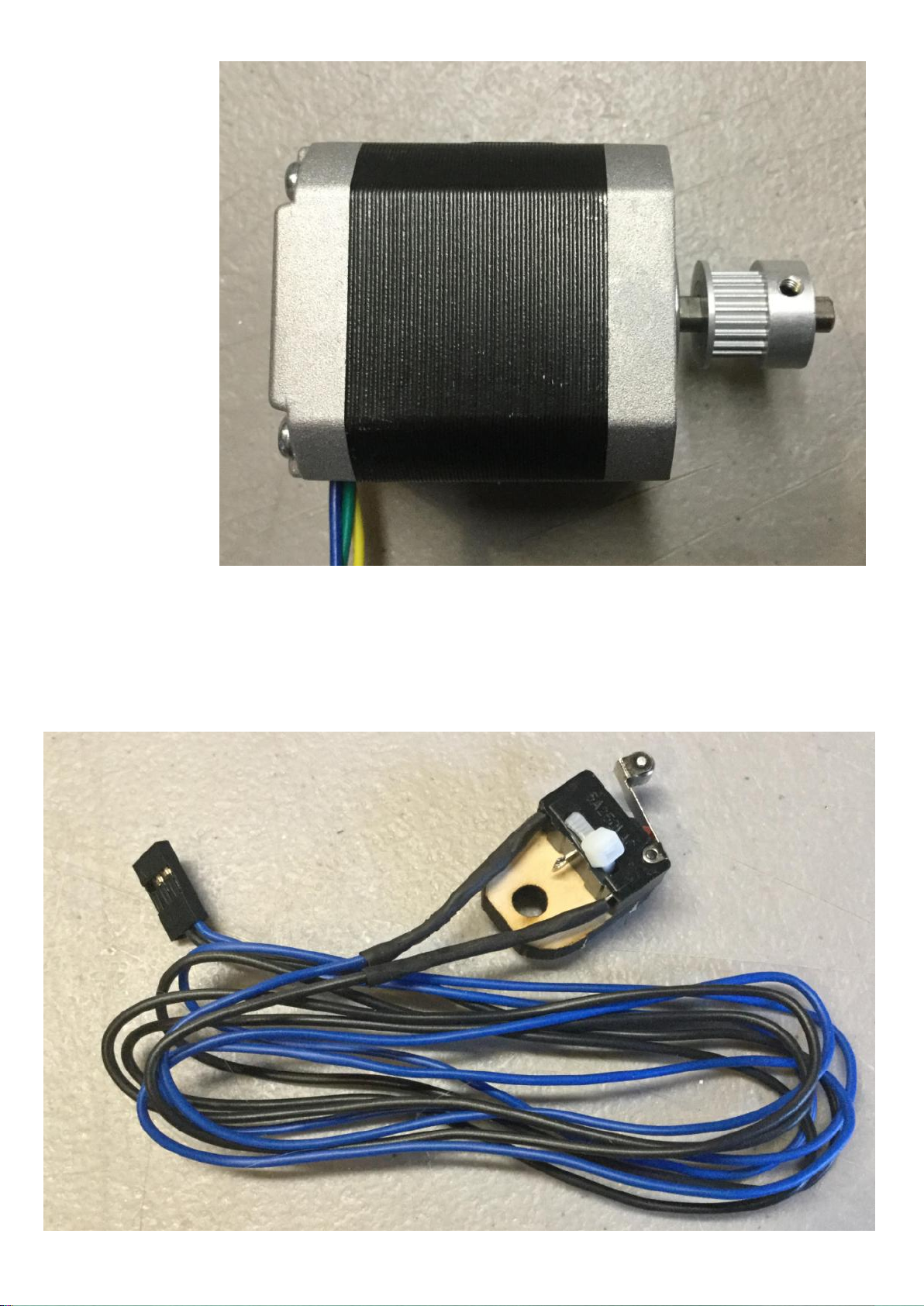
To start install a
GT2 gear onto a
motor as shown
below, make
sure to align one
of the set screws
with the flat spot
on the Motor.
Using the Wood Endstop mount and a zip tie install the endstop as shown below.
17
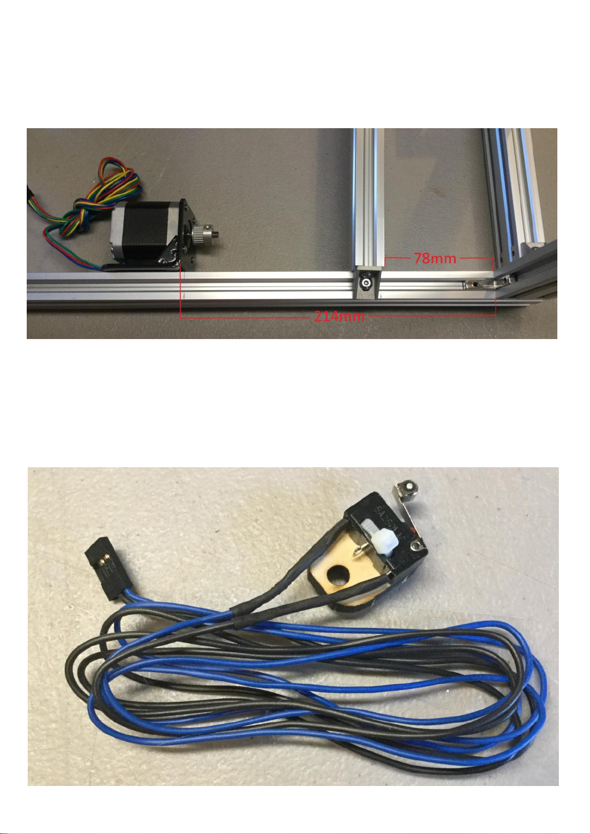
Next adjust the Y motor mount so the front of the mount is 214mm away from the
inside of the extrusion as shown below, then move the extrusion in between the motor
and side of the frame so its 78mm from the inside of the extrusion as shown below.
Next install the Motor with the GT2 gear using 4 of the M3x6mm bolts.

18
Install the endstop on the extrusion as shown below.
Adjust the two Z motor mounts so the surface the Z motor contacts is 55mm above the
extrusion as
shown.
Tighten the Z
motor mount
in place,
make sure the
mount is not
tilted. This
should let you
just barely
squeeze the
motor into
the mount.

19
Installl the two Z motors into the Z mounts using 4 M3x6mm bolts on each motor.

20
Get yourAluminum Heat bed mount, position the mount so the bolt hole shown by the
Blue arrow is in the top left corner. Install the M3x16mm bolt with an M3 Nylon lock
nut, then install a 2nd M3 Nylon lock nut onto the end of the bolt. (If you have
upgraded your Y Extrusions to 20x40 you will want to install the M3x16mm Bolt and
nut shown by the blue arrow in a hole 20mm to the right to allow for the thicker
extrusion, you may need to drill a new hole if your kit didn’t ship with the wider Y
extrusion)
Install the 4 M5x30mm bolts in the 4 larger holes as shown by the Red and Green
Arrows, then install an Aluminum Spacer on the bolts with the Red arrows and an
eccentric spacer on the ones with the Green Arrows. Turn the Eccentric spacers so the
Fat part of the spacer is closer to the center of the heat bed mount.
Table of contents
Other Makerfarm 3D Printer manuals


