Makita GA035G User manual

GA035G
EN Cordless Angle Grinder INSTRUCTION MANUAL 7
SV Batteridriven
vinkelslipmaskin BRUKSANVISNING 17
NO Batteridrevet vinkelsliper BRUKSANVISNING 27
FI Akkukäyttöinen
kulmahiomakone KÄYTTÖOHJE 37
DA Ledningsfri vinkelsliber BRUGSANVISNING 47
LV Bezvada leņķa slīpmašīna LIETOŠANAS INSTRUKCIJA 57
LT Belaidis kampinis šlifuoklis NAUDOJIMO INSTRUKCIJA 67
ET Juhtmeta nurklihvija KASUTUSJUHEND 77
RU Аккумуляторная угловая
шлифмашина РУКОВОДСТВО ПО
ЭКСПЛУАТАЦИИ 87

1
2
3
Fig.1
1
2
Fig.2
1
Fig.3
1
Fig.4
1
Fig.5
Fig.6
1
3
2
Fig.7
2

1
2
A
B
B
Fig.8
1
2
A
B
B
B
C
C
Fig.9
3
2
4
1
Fig.10
1
2
Fig.11
2
3
4
1
Fig.12
3

2
3
1
Fig.13
2
3
4
1
Fig.14
1
Fig.15
12
Fig.16
Fig.17
1
2
4
3
Fig.18
11
44
23
Fig.19
11
44
23
Fig.20
4

1
Fig.21
1
Fig.22
Fig.23
Fig.24
Fig.25
Fig.26
Fig.27
2
1
Fig.28
5

1
Fig.29
1
2
5
22
11
12
4
3
5
6
7
8
9
10
13
3
14
5
3
Fig.30
6

7ENGLISH
ENGLISH (Original instructions)
SPECIFICATIONS
Model: GA035G
Wheel diameter 150 mm (6″)
Max. wheel thickness 6.4 mm
Spindle thread M14 or 5/8″ (country specic)
Rated speed (n) 8,500 min-1
Overall length with BL4025 398 mm
with BL4040 410 mm
Net weight 3.0 - 3.7 kg
Rated voltage D.C. 36 V - 40 V max
•
Due to our continuing program of research and development, the specications herein are subject to change without notice.
• Specications may dier from country to country.
• The weight may dier depending on the attachment(s), including the battery cartridge. The lightest and heavi-
est combination, according to EPTA-Procedure 01/2014, are shown in the table.
Applicable battery cartridge and charger
Battery cartridge BL4025 / BL4040
Charger DC40RA
•
Some of the battery cartridges and chargers listed above may not be available depending on your region of residence.
WARNING: Only use the battery cartridges and chargers listed above. Use of any other battery cartridges
and chargers may cause injury and/or re.
Intended use
The tool is intended for grinding, sanding, wire brushing
and cutting of metal and stone materials without the use
of water.
Noise
The typical A-weighted noise level determined accord-
ing to EN60745-2-3:
Sound pressure level (LpA) : 82 dB(A)
Sound power level (LWA) : 93 dB (A)
Uncertainty (K) : 3 dB(A)
NOTE:
The declared noise emission value(s) has been
measured in accordance with a standard test method
and may be used for comparing one tool with another.
NOTE:
The declared noise emission value(s) may
also be used in a preliminary assessment of exposure.
WARNING: Wear ear protection.
WARNING:
The noise emission during actual
use of the power tool can dier from the declared
value(s) depending on the ways in which the tool is
used especially what kind of workpiece is processed.
WARNING:
Be sure to identify safety measures
to protect the operator that are based on an estima-
tion of exposure in the actual conditions of use (tak-
ing account of all parts of the operating cycle such
as the times when the tool is switched o and when
it is running idle in addition to the trigger time).
Vibration
The vibration total value (tri-axial vector sum) deter-
mined according to EN60745-2-3:
Work mode: surface grinding with normal side grip
Vibration emission (ah, AG) : 7.0 m/s2
Uncertainty (K) : 1.5 m/s2
Work mode: surface grinding with anti vibration side grip
Vibration emission (ah, AG) : 9.5 m/s2
Uncertainty (K) : 1.5 m/s2
Work mode: disc sanding with normal side grip
Vibration emission (ah, DS) : 4.5 m/s2
Uncertainty (K) : 1.5 m/s2
Work mode: disc sanding with anti vibration side grip
Vibration emission (ah, DS) : 4.0 m/s2
Uncertainty (K) : 1.5 m/s2
NOTE: The declared vibration total value(s) has been
measured in accordance with a standard test method
and may be used for comparing one tool with another.
NOTE: The declared vibration total value(s) may also
be used in a preliminary assessment of exposure.

8ENGLISH
WARNING: The vibration emission during
actual use of the power tool can dier from the
declared value(s) depending on the ways in which
the tool is used especially what kind of workpiece
is processed.
WARNING: Be sure to identify safety mea-
sures to protect the operator that are based on an
estimation of exposure in the actual conditions of
use (taking account of all parts of the operating
cycle such as the times when the tool is switched
o and when it is running idle in addition to the
trigger time).
WARNING: The declared vibration emission
value is used for main applications of the power tool.
However if the power tool is used for other applica-
tions, the vibration emission value may be dierent.
EC Declaration of Conformity
For European countries only
The EC declaration of conformity is included as Annex A
to this instruction manual.
SAFETY WARNINGS
General power tool safety warnings
WARNING: Read all safety warnings, instruc-
tions, illustrations and specications provided
with this power tool. Failure to follow all instructions
listed below may result in electric shock, re and/or
serious injury.
Save all warnings and instruc-
tions for future reference.
The term "power tool" in the warnings refers to your
mains-operated (corded) power tool or battery-operated
(cordless) power tool.
Cordless grinder safety warnings
Safety Warnings Common for Grinding, Sanding,
Wire Brushing, or Abrasive Cutting-O Operations:
1. This power tool is intended to function as a
grinder, sander, wire brush or cut-o tool.
Read all safety warnings, instructions, illus-
trations and specications provided with this
power tool. Failure to follow all instructions listed
below may result in electric shock, re and/or
serious injury.
2. Operations such as polishing are not rec-
ommended to be performed with this power
tool. Operations for which the power tool was not
designed may create a hazard and cause per-
sonal injury.
3. Do not use accessories which are not speci-
cally designed and recommended by the tool
manufacturer. Just because the accessory can
be attached to your power tool, it does not assure
safe operation.
4. The rated speed of the accessory must be at
least equal to the maximum speed marked on
the power tool. Accessories running faster than
their rated speed can break and y apart.
5. The outside diameter and the thickness of your
accessory must be within the capacity rating
of your power tool. Incorrectly sized accessories
cannot be adequately guarded or controlled.
6.
Threaded mounting of accessories must match
the grinder spindle thread. For accessories
mounted by anges, the arbour hole of the
accessory must t the locating diameter of the
ange. Accessories that do not match the mounting
hardware of the power tool will run out of balance,
vibrate excessively and may cause loss of control.
7.
Do not use a damaged accessory. Before each
use inspect the accessory such as abrasive
wheels for chips and cracks, backing pad for
cracks, tear or excess wear, wire brush for loose
or cracked wires. If power tool or accessory
is dropped, inspect for damage or install an
undamaged accessory. After inspecting and
installing an accessory, position yourself and
bystanders away from the plane of the rotating
accessory and run the power tool at maximum
no-load speed for one minute. Damaged acces-
sories will normally break apart during this test time.
8.
Wear personal protective equipment.
Depending on application, use face shield,
safety goggles or safety glasses. As appropri-
ate, wear dust mask, hearing protectors, gloves
and workshop apron capable of stopping small
abrasive or workpiece fragments. The eye pro-
tection must be capable of stopping ying debris
generated by various operations. The dust mask
or respirator must be capable of ltrating particles
generated by your operation. Prolonged exposure
to high intensity noise may cause hearing loss.
9.
Keep bystanders a safe distance away from work
area. Anyone entering the work area must wear
personal protective equipment. Fragments of
workpiece or of a broken accessory may y away and
cause injury beyond immediate area of operation.
10. Hold the power tool by insulated gripping
surfaces only, when performing an operation
where the cutting tool may contact hidden
wiring. Contact with a "live" wire will also make
exposed metal parts of the power tool "live" and
could give the operator an electric shock.
11. Never lay the power tool down until the acces-
sory has come to a complete stop. The spinning
accessory may grab the surface and pull the
power tool out of your control.
12.
Do not run the power tool while carrying it at your
side. Accidental contact with the spinning accessory could
snag your clothing, pulling the accessory into your body.
13. Regularly clean the power tool’s air vents. The
motor’s fan will draw the dust inside the housing
and excessive accumulation of powdered metal
may cause electrical hazards.
14. Do not operate the power tool near ammable
materials. Sparks could ignite these materials.
15. Do not use accessories that require liquid
coolants. Using water or other liquid coolants
may result in electrocution or shock.

9ENGLISH
Kickback and Related Warnings
Kickback is a sudden reaction to a pinched or snagged
rotating wheel, backing pad, brush or any other acces-
sory. Pinching or snagging causes rapid stalling of the
rotating accessory which in turn causes the uncon-
trolled power tool to be forced in the direction opposite
of the accessory’s rotation at the point of the binding.
For example, if an abrasive wheel is snagged or
pinched by the workpiece, the edge of the wheel that is
entering into the pinch point can dig into the surface of
the material causing the wheel to climb out or kick out.
The wheel may either jump toward or away from the
operator, depending on direction of the wheel’s move-
ment at the point of pinching. Abrasive wheels may also
break under these conditions.
Kickback is the result of power tool misuse and/or
incorrect operating procedures or conditions and can be
avoided by taking proper precautions as given below.
1. Maintain a rm grip on the power tool and
position your body and arm to allow you to
resist kickback forces. Always use auxiliary
handle, if provided, for maximum control over
kickback or torque reaction during start-up.
The operator can control torque reactions or kick-
back forces, if proper precautions are taken.
2. Never place your hand near the rotating acces-
sory. Accessory may kickback over your hand.
3. Do not position your body in the area where
power tool will move if kickback occurs.
Kickback will propel the tool in direction opposite
to the wheel’s movement at the point of snagging.
4. Use special care when working corners, sharp
edges etc. Avoid bouncing and snagging the
accessory. Corners, sharp edges or bouncing
have a tendency to snag the rotating accessory
and cause loss of control or kickback.
5. Do not attach a saw chain woodcarving blade
or toothed saw blade. Such blades create fre-
quent kickback and loss of control.
Safety Warnings Specic for Grinding and Abrasive
Cutting-O Operations:
1. Use only wheel types that are recommended
for your power tool and the specic guard
designed for the selected wheel. Wheels for
which the power tool was not designed cannot be
adequately guarded and are unsafe.
2. The grinding surface of centre depressed
wheels must be mounted below the plane of
the guard lip. An improperly mounted wheel that
projects through the plane of the guard lip cannot
be adequately protected.
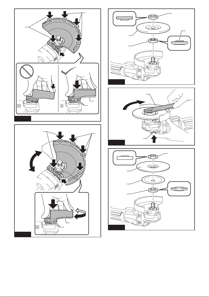
3. The guard must be securely attached to the
power tool and positioned for maximum safety,
so the least amount of wheel is exposed
towards the operator. The guard helps to protect
the operator from broken wheel fragments, acci-
dental contact with wheel and sparks that could
ignite clothing.
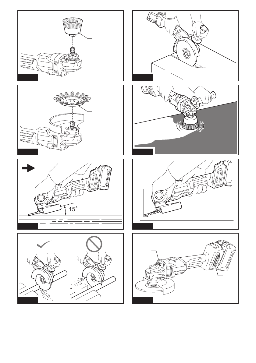
4. Wheels must be used only for recommended
applications. For example: do not grind with
the side of cut-o wheel. Abrasive cut-o wheels
are intended for peripheral grinding, side forces
applied to these wheels may cause them to
shatter.
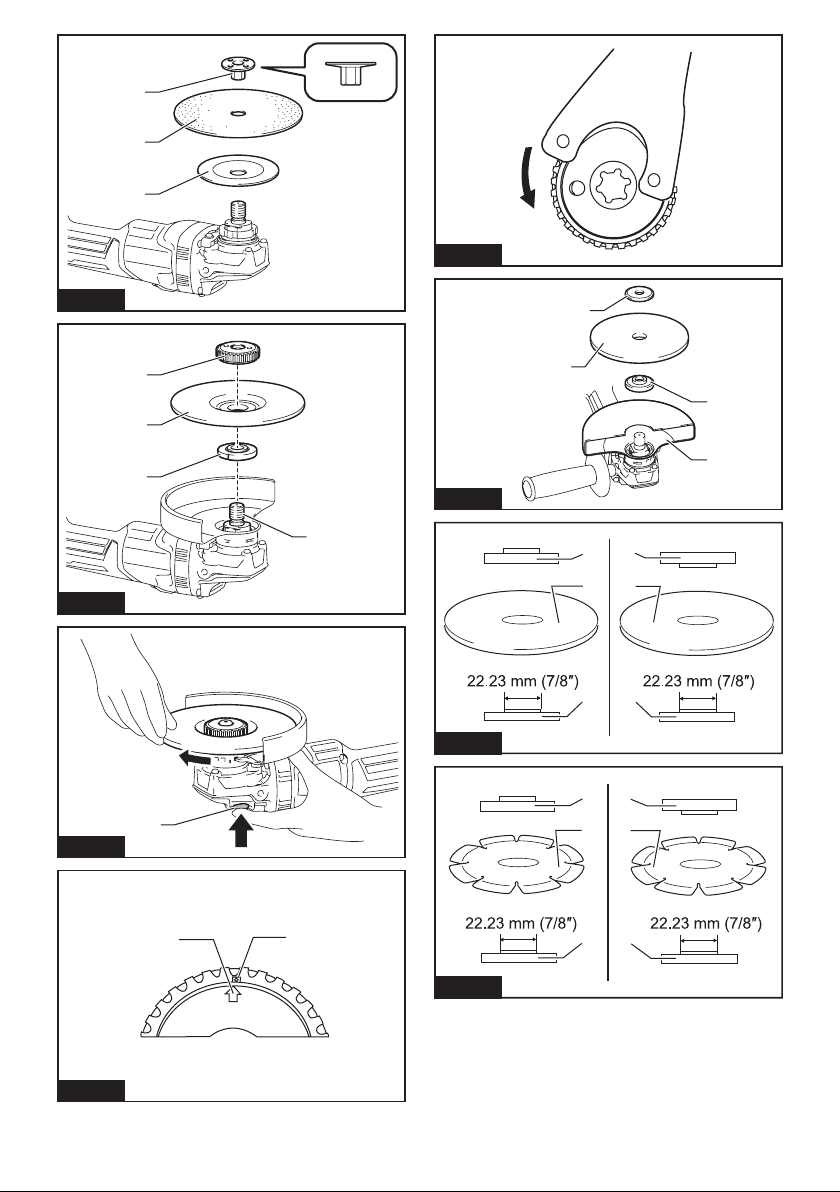
5. Always use undamaged wheel anges that are
of correct size and shape for your selected
wheel. Proper wheel anges support the wheel
thus reducing the possibility of wheel breakage.
Flanges for cut-o wheels may be dierent from
grinding wheel anges.
6. Do not use worn down wheels from larger
power tools. Wheel intended for larger power tool
is not suitable for the higher speed of a smaller
tool and may burst.
Additional Safety Warnings Specic for Abrasive
Cutting-O Operations:
1. Do not “jam“ the cut-o wheel or apply exces-
sive pressure. Do not attempt to make an
excessive depth of cut. Overstressing the wheel
increases the loading and susceptibility to twisting
or binding of the wheel in the cut and the possibil-
ity of kickback or wheel breakage.
2. Do not position your body in line with and
behind the rotating wheel. When the wheel, at
the point of operation, is moving away from your
body, the possible kickback may propel the spin-
ning wheel and the power tool directly at you.
3. When wheel is binding or when interrupting
a cut for any reason, switch o the power
tool and hold the power tool motionless until
the wheel comes to a complete stop. Never
attempt to remove the cut-o wheel from the
cut while the wheel is in motion otherwise
kickback may occur. Investigate and take correc-
tive action to eliminate the cause of wheel binding.
4. Do not restart the cutting operation in the
workpiece. Let the wheel reach full speed and
carefully re-enter the cut. The wheel may bind,
walk up or kickback if the power tool is restarted in
the workpiece.
5. Support panels or any oversized workpiece to
minimize the risk of wheel pinching and kick-
back. Large workpieces tend to sag under their
own weight. Supports must be placed under the
workpiece near the line of cut and near the edge
of the workpiece on both sides of the wheel.
6. Use extra caution when making a “pocket cut”
into existing walls or other blind areas. The
protruding wheel may cut gas or water pipes, elec-
trical wiring or objects that can cause kickback.
Safety Warnings Specic for Sanding Operations:
1. Do not use excessively oversized sanding
disc paper. Follow manufacturers recommen-
dations, when selecting sanding paper. Larger
sanding paper extending beyond the sanding
pad presents a laceration hazard and may cause
snagging, tearing of the disc or kickback.
Safety Warnings Specic for Wire Brushing Operations:
1. Be aware that wire bristles are thrown by the
brush even during ordinary operation. Do not
overstress the wires by applying excessive
load to the brush. The wire bristles can easily
penetrate light clothing and/or skin.
2. If the use of a guard is recommended for wire
brushing, do not allow any interference of the
wire wheel or brush with the guard. Wire wheel
or brush may expand in diameter due to work load
and centrifugal forces.

10 ENGLISH
Additional Safety Warnings:
1.
When using depressed centre grinding wheels,
be sure to use only berglass-reinforced wheels.
2. NEVER USE Stone Cup type wheels with this
grinder. This grinder is not designed for these
types of wheels and the use of such a product
may result in serious personal injury.
3.
Be careful not to damage the spindle, the ange (espe-
cially the installing surface) or the lock nut. Damage to
these parts could result in wheel breakage.
4. Make sure the wheel is not contacting the
workpiece before the switch is turned on.
5. Before using the tool on an actual workpiece,
let it run for a while. Watch for vibration or
wobbling that could indicate poor installation
or a poorly balanced wheel.
6. Use the specied surface of the wheel to per-
form the grinding.
7. Do not leave the tool running. Operate the tool
only when hand-held.
8. Do not touch the workpiece immediately after
operation; it may be extremely hot and could
burn your skin.
9. Do not touch accessories immediately after
operation; it may be extremely hot and could
burn your skin.
10. Observe the instructions of the manufacturer
for correct mounting and use of wheels.
Handle and store wheels with care.
11. Do not use separate reducing bushings or
adaptors to adapt large hole abrasive wheels.
12. Use only anges specied for this tool.
13. For tools intended to be tted with threaded
hole wheel, ensure that the thread in the wheel
is long enough to accept the spindle length.
14.
Check that the workpiece is properly supported.
15. Pay attention that the wheel continues to
rotate after the tool is switched o.
16.
If working place is extremely hot and humid, or
badly polluted by conductive dust, use a short-cir-
cuit breaker (30 mA) to assure operator safety.
17. Do not use the tool on any materials contain-
ing asbestos.
18. When use cut-o wheel, always work with
the dust collecting wheel guard required by
domestic regulation.
19. Cutting discs must not be subjected to any
lateral pressure.
20. Do not use cloth work gloves during operation.
Fibers from cloth gloves may enter the tool, which
causes tool breakage.
21. Make sure there are no electrical cables, water
pipes, gas pipes etc. that could cause a hazard
if damaged by use of the tool.
SAVE THESE INSTRUCTIONS.
WARNING: DO NOT let comfort or familiarity
with product (gained from repeated use) replace
strict adherence to safety rules for the subject
product. MISUSE or failure to follow the safety
rules stated in this instruction manual may cause
serious personal injury.
Important safety instructions for
battery cartridge
1. Before using battery cartridge, read all instruc-
tions and cautionary markings on (1) battery
charger, (2) battery, and (3) product using
battery.
2. Do not disassemble or tamper the battery
cartridge. It may result in a re, excessive heat,
or explosion.
3. If operating time has become excessively
shorter, stop operating immediately. It may
result in a risk of overheating, possible burns
and even an explosion.
4. If electrolyte gets into your eyes, rinse them
out with clear water and seek medical atten-
tion right away. It may result in loss of your
eyesight.
5. Do not short the battery cartridge:
(1) Do not touch the terminals with any con-
ductive material.
(2) Avoid storing battery cartridge in a con-
tainer with other metal objects such as
nails, coins, etc.
(3) Do not expose battery cartridge to water
or rain.
A battery short can cause a large current
ow, overheating, possible burns and even a
breakdown.
6. Do not store and use the tool and battery car-
tridge in locations where the temperature may
reach or exceed 50 °C (122 °F).
7. Do not incinerate the battery cartridge even if
it is severely damaged or is completely worn
out. The battery cartridge can explode in a re.
8. Do not nail, cut, crush, throw, drop the battery
cartridge, or hit against a hard object to the
battery cartridge. Such conduct may result in a
re, excessive heat, or explosion.
9. Do not use a damaged battery.
10. The contained lithium-ion batteries are subject
to the Dangerous Goods Legislation require-
ments.
For commercial transports e.g. by third parties,
forwarding agents, special requirement on pack-
aging and labeling must be observed.
For preparation of the item being shipped, consult-
ing an expert for hazardous material is required.
Please also observe possibly more detailed
national regulations.
Tape or mask o open contacts and pack up the
battery in such a manner that it cannot move
around in the packaging.
11. When disposing the battery cartridge, remove
it from the tool and dispose of it in a safe
place. Follow your local regulations relating to
disposal of battery.
12. Use the batteries only with the products
specied by Makita. Installing the batteries to
non-compliant products may result in a re, exces-
sive heat, explosion, or leak of electrolyte.

11 ENGLISH
13. If the tool is not used for a long period of time,
the battery must be removed from the tool.
14. During and after use, the battery cartridge may
take on heat which can cause burns or low
temperature burns. Pay attention to the han-
dling of hot battery cartridges.
15. Do not touch the terminal of the tool imme-
diately after use as it may get hot enough to
cause burns.
16. Do not allow chips, dust, or soil stuck into the
terminals, holes, and grooves of the battery
cartridge. It may result in poor performance or
breakdown of the tool or battery cartridge.
17. Unless the tool supports the use near
high-voltage electrical power lines, do not use
the battery cartridge near a high-voltage elec-
trical power lines. It may result in a malfunction
or breakdown of the tool or battery cartridge.
18. Keep the battery away from children.
SAVE THESE INSTRUCTIONS.
CAUTION: Only use genuine Makita batteries.
Use of non-genuine Makita batteries, or batteries that
have been altered, may result in the battery bursting
causing res, personal injury and damage. It will
also void the Makita warranty for the Makita tool and
charger.
Tips for maintaining maximum
battery life
1. Charge the battery cartridge before completely
discharged. Always stop tool operation and
charge the battery cartridge when you notice
less tool power.
2. Never recharge a fully charged battery car-
tridge. Overcharging shortens the battery
service life.
3. Charge the battery cartridge with room tem-
perature at 10 °C - 40 °C (50 °F - 104 °F). Let
a hot battery cartridge cool down before
charging it.
4. When not using the battery cartridge, remove
it from the tool or the charger.
5. Charge the battery cartridge if you do not use
it for a long period (more than six months).
FUNCTIONAL DESCRIPTION
CAUTION: Always be sure that the tool is
switched o and the battery cartridge is removed
before adjusting or checking function on the tool.
Installing or removing battery cartridge
CAUTION: Always switch o the tool before
installing or removing of the battery cartridge.
CAUTION: Hold the tool and the battery car-
tridge rmly when installing or removing battery
cartridge. Failure to hold the tool and the battery
cartridge rmly may cause them to slip o your hands
and result in damage to the tool and battery cartridge
and a personal injury.
► Fig.1: 1. Red indicator 2. Button 3. Battery cartridge
To remove the battery cartridge, slide it from the tool
while sliding the button on the front of the cartridge.
To install the battery cartridge, align the tongue on the
battery cartridge with the groove in the housing and slip
it into place. Insert it all the way until it locks in place
with a little click. If you can see the red indicator on the
upper side of the button, it is not locked completely.
CAUTION: Always install the battery cartridge
fully until the red indicator cannot be seen. If not,
it may accidentally fall out of the tool, causing injury to
you or someone around you.
CAUTION: Do not install the battery cartridge
forcibly. If the cartridge does not slide in easily, it is
not being inserted correctly.
Indicating the remaining battery capacity
Press the check button on the battery cartridge to indi-
cate the remaining battery capacity. The indicator lamps
light up for a few seconds.
► Fig.2: 1. Indicator lamps 2. Check button
Indicator lamps Remaining
capacity
Lighted O Blinking
75% to 100%
50% to 75%
25% to 50%
0% to 25%
Charge the
battery.
The battery
may have
malfunctioned.

12 ENGLISH
NOTE: Depending on the conditions of use and the
ambient temperature, the indication may dier slightly
from the actual capacity.
NOTE: The rst (far left) indicator lamp will blink when
the battery protection system works.
Tool / battery protection system
The tool is equipped with a tool/battery protection system. This
system automatically cuts o power to the motor to extend tool
and battery life. The tool will automatically stop during operation if
the tool or battery is placed under one of the following conditions:
Overload protection
When the tool/battery is operated in a manner that causes
it to draw an abnormally high current, the tool automat-
ically stops without any indication. In this situation, turn
the tool o and stop the application that caused the tool to
become overloaded. Then turn the tool on to restart.
Overheat protection
When the tool/battery is overheated, the tool stops automati-
cally. Let the tool cool down before turning the tool on again.
Overdischarge protection
When the battery capacity is not enough, the tool stops
automatically. In this case, remove the battery from the
tool and charge the battery.
Releasing protection lock
When the protection system works repeatedly, the tool is locked.
In this situation, the tool does not start even if turning the tool
o and on. To release the protection lock, remove the battery,
set it to the battery charger and wait until the charging nishes.
Shaft lock
Press the shaft lock to prevent spindle rotation when
installing or removing accessories.
► Fig.3: 1. Shaft lock
NOTICE: Never actuate the shaft lock when the
spindle is moving. The tool may be damaged.
Switch action
CAUTION:
Before installing the battery cartridge
into the tool, always check to see that the slide switch
actuates properly and returns to the "OFF" position
when the rear of the slide switch is depressed.
CAUTION: Switch can be locked in "ON" posi-
tion for ease of operator comfort during extended
use. Apply caution when locking tool in "ON"
position and maintain rm grasp on tool.
To start the tool, press down the rear end of the slide switch and
then slide it toward the “I (ON)” position. For continuous opera-
tion, press down the front end of the slide switch to lock it.
► Fig.4: 1. Slide switch
To stop the tool, press down the rear end of the slide
switch so that it returns to the “O (OFF)” position.
► Fig.5: 1. Slide switch
Accidental re-start preventive
function
When installing the battery cartridge while the slide
switch in the "I (ON)" position, the tool does not start.
To start the tool, rst slide the slide switch toward the
"O (OFF)" position and then slide it toward the "I (ON)"
position.
Electronic torque control function
The tool electronically detects situations where the
wheel or accessory may be at risk to be bound. In the
situation, the tool is automatically shut o to prevent
further rotation of the spindle (it does not prevent
kickback).
To restart the tool, switch o the tool rst, remove the
cause of sudden drop in the rotation speed, and then
turn the tool on.
Soft start feature
Soft start feature reduces starting reaction.
ASSEMBLY
CAUTION: Always be sure that the tool is
switched o and the battery cartridge is removed
before adjusting or checking function on the tool.
Installing side grip (handle)
CAUTION: Always be sure that the side grip is
installed securely before operation.
Screw the side grip securely on the position of the tool
as shown in the gure.
► Fig.6
Installing or removing wheel guard
WARNING: When using a depressed center
wheel, ap disc, ex wheel or wire wheel brush,
the wheel guard must be tted on the tool so that
the closed side of the guard always points toward
the operator.
WARNING: Make sure that the wheel guard is
securely locked by the lock lever with one of the
holes on the wheel guard.
WARNING: When using an abrasive cut-o
/ diamond wheel, be sure to use only the special
wheel guard designed for use with cut-o wheels.
(In some European countries, when using a diamond
wheel, the ordinary guard can be used. Follow the
regulations in your country.)

13 ENGLISH
For depressed center wheel, ap disc,
ex wheel, wire wheel brush / abrasive
cut-o wheel, diamond wheel
1. While pushing the lock lever, mount the wheel
guard with the protrusions on the wheel guard aligned
with the notches on the bearing box.
► Fig.7: 1. Lock lever 2. Notch 3. Protrusion
2. While pushing the lock lever toward A, push in the
wheel guard by holding down the portions B as shown
in the gure.
► Fig.8: 1. Wheel guard 2. Hole
NOTE: Push down the wheel guard straight.
Otherwise, you cannot push the wheel guard
completely.
3. While keeping the lock lever and wheel guard
position as described in step 2, rotate the wheel guard
toward C, and then, change the angle of the wheel
guard according to the work so that the operator can be
protected. Align the lock lever with one of the holes in
the wheel guard, and then release the lock lever to lock
the wheel guard.
► Fig.9: 1. Wheel guard 2. Hole
NOTE: Push the wheel guard completely. Otherwise,
you cannot rotate the wheel guard.
To remove wheel guard, follow the installation proce-
dure in reverse.
Installing or removing depressed
center wheel or ap disc
Optional accessory
WARNING: When using a depressed center
wheel or ap disc, the wheel guard must be tted
on the tool so that the closed side of the guard
always points toward the operator.
CAUTION: Make sure that the mounting part
of the inner ange ts into the inner diameter of
the depressed center wheel / ap disc perfectly.
Mounting the inner ange on the wrong side may
result in the dangerous vibration.
Mount the inner ange onto the spindle.
Make sure to t the dented part of the inner ange onto
the straight part at the bottom of the spindle.
Fit the depressed center wheel / ap disc on the inner
ange and screw the lock nut onto the spindle.
► Fig.10: 1. Lock nut 2. Depressed center wheel
3. Inner ange 4. Mounting part
To tighten the lock nut, press the shaft lock rmly so
that the spindle cannot revolve, then use the lock nut
wrench and securely tighten clockwise.
► Fig.11: 1. Lock nut wrench 2. Shaft lock
To remove the wheel, follow the installation procedure
in reverse.
Installing or removing ex wheel
Optional accessory
WARNING: Always use supplied guard when
ex wheel is on tool. Wheel can shatter during use
and guard helps to reduce chances of personal injury.
► Fig.12: 1. Lock nut 2. Flex wheel 3. Back up pad
4. Inner ange
Follow instructions for depressed center wheel but also
use back up pad over wheel. See order of assembly on
accessories page in this manual.
Installing or removing abrasive disc
Optional accessory
► Fig.13: 1. Sanding lock nut 2. Abrasive disc
3. Rubber pad
1. Mount the rubber pad onto the spindle.
2. Fit the disc on the rubber pad and screw the sand-
ing lock nut onto the spindle.
3. Hold the spindle with the shaft lock, and securely
tighten the sanding lock nut clockwise with the lock nut
wrench.
To remove the disc, follow the installation procedure in
reverse.
NOTE: Use sander accessories specied in this man-
ual. These must be purchased separately.
Installing or removing Ezynut
Optional accessory
CAUTION: Do not use Ezynut with Super Flange
or angle grinder with “F” on the end of the model
No. Those anges are so thick that the entire thread
cannot be retained by the spindle.
► Fig.14: 1. Ezynut 2. Abrasive wheel 3. Inner ange
4. Spindle
Mount inner ange, abrasive wheel and Ezynut onto the
spindle so that Makita Logo on Ezynut faces outside.
► Fig.15: 1. Shaft lock
Press shaft lock rmly and tighten Ezynut by turning the
abrasive wheel clockwise as far as it turns.
Turn the outside ring of Ezynut counterclockwise to
loosen.
► Fig.16: 1. Arrow 2. Notch
► Fig.17
NOTE: Ezynut can be loosened by hand as long
as the arrow points the notch. Otherwise a lock nut
wrench is required to loosen it. Insert one pin of the
wrench into a hole and turn Ezynut counterclockwise.

14 ENGLISH
Installing abrasive cut-o / diamond wheel
Optional accessory
WARNING: When using an abrasive cut-o
/ diamond wheel, be sure to use only the special
wheel guard designed for use with cut-o wheels.
(In some European countries, when using a diamond
wheel, the ordinary guard can be used. Follow the
regulations in your country.)
WARNING: NEVER use cut-o wheel for side
grinding.
► Fig.18: 1. Lock nut 2. Abrasive cut-o wheel / dia-
mond wheel 3. Inner ange 4. Wheel guard
for abrasive cut-o wheel / diamond wheel
As for the installation, follow the instructions for
depressed center wheel.
The direction for mounting the lock nut and the
inner ange varies by wheel type and thickness.
Refer to the following gures.
When installing the abrasive cut-o wheel:
► Fig.19: 1. Lock nut 2. Abrasive cut-o wheel
(Thinner than 4 mm (5/32")) 3. Abrasive cut-
o wheel (4 mm (5/32") or thicker) 4. Inner
ange
When installing the diamond wheel:
► Fig.20: 1. Lock nut 2. Diamond wheel (Thinner than
4 mm (5/32″)) 3. Diamond wheel (4 mm
(5/32″) or thicker) 4. Inner ange
Installing wire cup brush
Optional accessory
CAUTION: Do not use brush that is damaged,
or which is out of balance. Use of damaged brush
could increase potential for injury from contact with
broken brush wires.
► Fig.21: 1. Wire cup brush
Remove the battery cartridge from the tool and place it
upside down allowing easy access to spindle.
Remove any accessories on spindle. Thread wire cup
brush onto spindle and tighten with supplied wrench.
Installing wire wheel brush
Optional accessory
CAUTION: Do not use wire wheel brush that
is damaged, or which is out of balance. Use of
damaged wire wheel brush could increase potential
for injury from contact with broken wires.
CAUTION: ALWAYS use guard with wire
wheel brushes, assuring diameter of wheel ts
inside guard. Wheel can shatter during use and
guard helps to reduce chances of personal injury.
► Fig.22: 1. Wire wheel brush
Remove the battery cartridge from the tool and place it
upside down allowing easy access to spindle.
Remove any accessories on spindle. Thread wire wheel
brush onto spindle and tighten with the wrenches.
OPERATION
WARNING: It should never be necessary to
force the tool. The weight of the tool applies ade-
quate pressure. Forcing and excessive pressure
could cause dangerous wheel breakage.
WARNING: ALWAYS replace wheel if tool is
dropped while grinding.
WARNING: NEVER bang or hit grinding disc
or wheel onto work.
WARNING: Avoid bouncing and snagging
the wheel, especially when working corners,
sharp edges etc. This can cause loss of control and
kickback.
WARNING: NEVER use tool with wood cutting
blades and other saw blades. Such blades when
used on a grinder frequently kick and cause loss of
control leading to personal injury.
CAUTION: Never switch on the tool when it
is in contact with the workpiece, it may cause an
injury to operator.
CAUTION: Always wear safety goggles or a
face shield during operation.
CAUTION: After operation, always switch o
the tool and wait until the wheel has come to a
complete stop before putting the tool down.
CAUTION: ALWAYS hold the tool rmly with
one hand on housing and the other on the side
grip (handle).
Grinding and sanding operation
► Fig.23
Turn the tool on and then apply the wheel or disc to the
workpiece.
In general, keep the edge of the wheel or disc at an
angle of about 15° to the workpiece surface.
During the break-in period with a new wheel, do not
work the grinder in forward direction or it may cut into
the workpiece. Once the edge of the wheel has been
rounded o by use, the wheel may be worked in both
forward and backward direction.

15 ENGLISH
Operation with abrasive cut-o /
diamond wheel
Optional accessory
WARNING: Do not "jam" the wheel or apply
excessive pressure. Do not attempt to make an
excessive depth of cut. Overstressing the wheel
increases the loading and susceptibility to twisting
or binding of the wheel in the cut and the possibility
of kickback, wheel breakage and overheating of the
motor may occur.
WARNING: Do not start the cutting operation
in the workpiece. Let the wheel reach full speed
and carefully enter into the cut moving the tool
forward over the workpiece surface. The wheel
may bind, walk up or kickback if the power tool is
started in the workpiece.
WARNING: During cutting operations, never
change the angle of the wheel. Placing side pres-
sure on the cut-o wheel (as in grinding) will cause
the wheel to crack and break, causing serious per-
sonal injury.
WARNING: A diamond wheel shall be oper-
ated perpendicular to the material being cut.
Usage example: operation with abrasive cut-o
wheel
► Fig.24
Usage example: operation with diamond wheel
► Fig.25
Operation with wire cup brush
Optional accessory
CAUTION: Check operation of brush by run-
ning tool with no load, insuring that no one is in
front of or in line with brush.
NOTICE: Avoid applying too much pressure
which causes over bending of wires when using
the wire cup brush. It may lead to premature
breakage.
Usage example: operation with wire cup brush
► Fig.26
Operation with wire wheel brush
Optional accessory
CAUTION: Check operation of wire wheel
brush by running tool with no load, insuring that
no one is in front of or in line with the wire wheel
brush.
NOTICE: Avoid applying too much pressure
which causes over bending of wires when
using wire wheel brush. It may lead to premature
breakage.
Usage example: operation with wire wheel brush
► Fig.27
MAINTENANCE
CAUTION: Always be sure that the tool is
switched o and the battery cartridge is removed
before attempting to perform inspection or
maintenance.
NOTICE: Never use gasoline, benzine, thinner,
alcohol or the like. Discoloration, deformation or
cracks may result.
To maintain product SAFETY and RELIABILITY, repairs,
any other maintenance or adjustment should be per-
formed by Makita Authorized Service Centers, always
using Makita replacement parts.
Air vent cleaning
The tool and its air vents have to be kept clean.
Regularly clean the tool's air vents or whenever the
vents start to become obstructed.
► Fig.28: 1. Exhaust vent 2. Inhalation vent
Remove the dust cover from inhalation vent and clean it
for smooth air circulation.
► Fig.29: 1. Dust cover
NOTICE: Clean out the dust cover when it is
clogged with dust or foreign matters. Continuing
operation with a clogged dust cover may damage the
tool.

16 ENGLISH
OPTIONAL ACCESSORIES
CAUTION: These accessories or attachments are recommended for use with your Makita tool spec-
ied in this manual. The use of any other accessories or attachments might present a risk of injury to persons.
Only use accessory or attachment for its stated purpose.
If you need any assistance for more details regarding these accessories, ask your local Makita Service Center.
• Makita genuine battery and charger
► Fig.30
-150 mm (6″) model
1Grip 36
2Wheel Guard (for grinding wheel)
3Inner ange
4Depressed center wheel / Flap disc
5Lock nut
6Back up pad
7Flex wheel
8Rubber pad 125
9Abrasive disc
10 Sanding lock nut
11 Wire wheel brush
12 Wire cup brush
13 Wheel Guard (for cut-o wheel) *1
14 Abrasive cut-o wheel / Diamond wheel
-Lock nut wrench
NOTE: *1 In some European countries, when using a diamond wheel, the ordinary guard can be used instead of the
special guard covering the both side of the wheel. Follow the regulations in your country.
NOTE: Some items in the list may be included in the tool package as standard accessories. They may dier from
country to country.

17 SVENSKA
SVENSKA (Originalinstruktioner)
SPECIFIKATIONER
Modell: GA035G
Kapskivans diameter 150 mm (6″)
Max. skivtjocklek 6,4 mm
Spindelgänga M14 eller 5/8″ (landsspecikt)
Nominellt varvtal (n) 8 500 min-1
Total längd med BL4025 398 mm
med BL4040 410 mm
Nettovikt 3,0 - 3,7 kg
Märkspänning 36 V - 40 V likström max
•
På grund av vårt pågående program för forskning och utveckling kan dessa specikationer ändras utan föregående meddelande.
• Specikationer kan variera mellan olika länder.
• Vikten kan variera beroende på tillbehören, inklusive batterikassett. Den lättaste och den tyngsta kombinatio-
nen enligt EPTA-procedur 01/2014 visas i tabellen.
Tillgänglig batterikassett och laddare
Batterikassett BL4025/BL4040
Laddare DC40RA
• Vissa av batterikassetterna och laddarna på listan ovan kanske inte nns tillgängliga i din region.
VARNING: Använd endast batterikassetter och laddare från listan ovan. Användning av andra batterikas-
setter och laddare kan orsaka personskada och/eller brand.
Avsedd användning
Verktyget är avsett för slipning och kapning i trä och
stenmaterial utan användning av vatten.
Buller
Den normala bullernivån för A-belastning är bestämd
enligt EN60745-2-3:
Ljudtrycksnivå (LpA) : 82 dB (A)
Ljudeektnivå (LWA) : 93 dB (A)
Mättolerans (K): 3 dB (A)
OBS: Det deklarerade bullervärdet har uppmätts i
enlighet med standardtestmetoden och kan användas
för jämförandet av en maskin med en annan.
OBS:
Det deklarerade bulleremissionsvärdet kan också använ-
das i en preliminär bedömning av exponering för vibration.
VARNING: Använd hörselskydd.
VARNING:
Bulleremissionen under faktisk
användning av maskinen kan skilja sig från det dekla-
rerade värdet, beroende på hur maskinen används och
särskilt vilken typ av arbetsstycke som behandlas.
VARNING:
Var noga med att identiera säker-
hetsåtgärder för att skydda användaren, vilka är
grundade på en uppskattning av graden av exponering
för vibrationer under de faktiska användningsförhål-
landena, (ta, förutom avtryckartiden, med alla delar av
användarcykeln i beräkningen, som till exempel tiden
då maskinen är avstängd och när den går på tomgång).
Vibration
Det totala vibrationsvärdet (treaxlad vektorsumma)
bestämt enligt EN60745-2-3:
Arbetsläge: planslipning med normalt sidohandtag
Vibrationsemission (ah, AG): 7,0 m/s2
Mättolerans (K): 1,5 m/s2
Arbetsläge: planslipning med anti-vibrationssidohandtag
Vibrationsemission (ah, AG): 9,5 m/s2
Mättolerans (K): 1,5 m/s2
Arbetsläge: skivslipning med normalt sidohandtag
Vibrationsemission (ah, DS): 4,5 m/s2
Mättolerans (K): 1,5 m/s2
Arbetsläge: skivslipning med anti-vibrationssidohandtag
Vibrationsemission (ah, DS): 4,0 m/s2
Mättolerans (K): 1,5 m/s2
OBS: Det deklarerade totala vibrationsvärdet har
uppmätts i enlighet med standardtestmetoden och
kan användas för jämförandet av en maskin med en
annan.
OBS: Det deklarerade totala vibrationsvärdet kan
också användas i en preliminär bedömning av expo-
nering för vibration.

18 SVENSKA
VARNING: Vibrationsemissionen under fak-
tisk användning av maskinen kan skilja sig från
det deklarerade värdet, beroende på hur maski-
nen används och särskilt vilken typ av arbetss-
tycke som behandlas.
VARNING: Var noga med att identiera säker-
hetsåtgärder för att skydda användaren, vilka är
grundade på en uppskattning av graden av expo-
nering för vibrationer under de faktiska använd-
ningsförhållandena, (ta, förutom avtryckartiden,
med alla delar av användarcykeln i beräkningen,
som till exempel tiden då maskinen är avstängd
och när den går på tomgång).
VARNING: Det deklarerade vibrationsemis-
sionsvärdet används för maskinens huvudsakliga
arbetsuppgifter. Om maskinen används för andra
arbetsuppgifter kan däremot vibrationsemissionsvär-
det bli annorlunda.
EG-försäkran om överensstämmelse
Gäller endast inom EU
EG-försäkran om överensstämmelse inkluderas som
bilaga A till denna bruksanvisning.
SÄKERHETSVARNINGAR
Allmänna säkerhetsvarningar för
maskiner
VARNING: Läs alla säkerhetsvarningar, anvis-
ningar, illustrationer och specikationer som
medföljer det här maskinen. Underlåtenhet att följa
instruktionerna kan leda till elstötar, brand och/eller
allvarliga personskador.
Spara alla varningar och instruk-
tioner för framtida referens.
Termen ”maskin” som anges i varningarna hänvisar till
din eldrivna maskin (sladdansluten) eller batteridrivna
maskin (sladdlös).
Säkerhetsvarningar för batteridriven
slipmaskin
Säkerhetsvarningar för slipning, stålborstning eller
abrasiv skärning:
1. Den här maskinen är utformad för att användas
för slipning, stålborstning eller som skärverk-
tyg. Läs alla säkerhetsvarningar, anvisningar,
illustrationer och specikationer som med-
följer den här maskinen. Underlåtenhet att följa
instruktionerna kan leda till elstötar, brand och/
eller allvarliga personskador.
2. Den här maskinen rekommenderas inte för
poleringsarbeten. Om maskinen används till
andra arbeten än de avsedda, kan det orsaka fara
och personskada.
3. Använd inte tillbehör som inte är särskilt till-
verkade och rekommenderade av maskinens
tillverkare. Även om ett tillbehör kan fästas på
maskinen garanterar detta inte säker funktion.
4.
Tillbehörets nominella varvtal måste vara minst
lika med det maximala varvtalet som anges på
verktyget. Tillbehör som används över det nomi-
nella varvtalet kan gå sönder och orsaka skador.
5. Tillbehörets ytterdiameter och tjocklek måste
vara anpassad till elverktygets kapacitets-
klassning. Tillbehör i olämplig storlek kan inte
skyddas eller styras tillräckligt väl.
6. Gängorna på tillbehör som monteras måste
stämma överens med spindelgängorna på
slipmaskinen. För tillbehör som monteras med
änsar måste tillbehörets centrumhål passa i
änsens lokaliseringsdiameter. Tillbehör som
inte passar exakt på maskinens monteringsbeslag
roterar ojämnt, vibrerar kraftigt och kan leda till att
du förlorar kontrollen.
7. Använd inte ett skadat tillbehör. Kontrollera
tillbehör som sliprondeller efter hack och
sprickor, underlagsplattor efter sprickor,
slitage och stålborstar efter lösa eller brutna
trådar. Om du tappar maskinen eller ett tillbe-
hör ska du kontrollera att det inte har uppstått
några skador, eller så ska tillbehöret bytas ut
mot ett oskadat. Efter kontroll och montering
av tillbehöret ska du och åskådare hålla er
borta från det roterande tillbehöret samtidigt
som du kör maskinen på full fart utan last i
en minut. Skadade tillbehör går normalt sönder
under den här testtiden.
8. Använd personlig skyddsutrustning. Använd
visir, korgglasögon eller skyddsglasögon
beroende på arbetsuppgift. Använd vid
behov dammskydd, hörselskydd, handskar
och skyddsförkläde som stoppar små bitar
slipmaterial eller fragment från arbetss-
tycket. Ögonskyddet måste kunna stoppa y-
gande fragment som uppstår vid olika arbeten.
Dammskyddet eller andningsskyddet måste kunna
ltrera partiklar som uppstår vid olika arbeten.
Lång tid i kraftigt buller kan orsaka hörselskador.
9.
Håll personer i omgivningen på säkert avstånd
från arbetsområdet. Alla som benner sig i
arbetsområdet måste använda skyddsutrustning.
Delar av arbetsstycket eller defekta tillbehör kan
yga iväg och orsaka skador utanför arbetsområdet.
10. Håll maskinen endast i de isolerade handtagen
om det nns risk för att skärverktyget kan
komma i kontakt med en dold elkabel. Om skär-
verktyget kommer i kontakt med en strömförande
ledning blir maskinens metalldelar strömförande
och kan ge användaren en elektrisk stöt.
11. Lägg aldrig elverktyget åt sidan förrän det har
stannat helt. Det roterande tillbehöret kan gripa
tag i underlaget och du kan förlora kontrollen över
maskinen.
12.
Kör inte verktyget samtidigt som du bär det.
Oavsiktlig kontakt med det roterande tillbehöret kan leda
till att det fastnar i dina kläder och dras in mot kroppen.
13. Rengör regelbundet verktygets ventilations-
öppningar. Motorns äkt suger in damm i höljet
och överdriven ansamling av pulveriserad metall
kan orsaka elektrisk fara.

19 SVENSKA
14. Använd inte verktyget i närheten av lättan-
tändliga material. Gnistor kan antända dessa
material.
15. Använd inte tillbehör som kräver ytande kyl-
vätskor. Att använda vatten eller andra ytande
kylvätskor kan orsaka dödsfall eller elektriska
stötar.
Bakåtkast och relaterade varningar
Bakåtkast är en plötslig reaktion på fastnypt roterande
hjul, underlagsplatta, borste eller annat tillbehör. Nyp
och kärvning orsakar stegring av det roterande tillbehö-
ret, och orsakar i sin tur att den okontrollerade maski-
nen tvingas i motsatt riktning vid kärvningspunkten.
Om till exempel en slipskiva fastnar i eller kläms fast av
arbetsstycket kan skivans kapande kant gräva sig in i
materialytan vid klämpunkten, vilket leder till att skivan
klättrar eller kastas tillbaka. Skivan kan antingen hoppa
mot eller från användaren, beroende på skivans rörel-
seriktning vid klämpunkten. Slipskivorna kan även gå
sönder under dessa omständigheter.
Bakåtkast beror på ovarsamhet och/eller felaktiga
arbetsrutiner, och kan undvikas genom att vidta nedan-
stående förebyggande åtgärder.
1. Se till att hålla verktyget i ett fast grepp och
placera kroppen och din arm på ett sätt som
gör att du kan stå emot kraften från bakåtkast.
Använd alltid ett extrahandtag, om sådant
nns, för maximal kontroll vid bakåtkast eller
vridrörelsen vid start. Användaren kan kontroll-
era vridrörelsen eller krafterna vid bakåtkast om
rätt försiktighetsåtgärder vidtas.
2. Placera aldrig din hand nära det roterande
tillbehöret. Tillbehöret kan kastas bakåt över din
hand.
3. Ställ dig inte där maskinen kommer att förytta
sig i händelse av bakåtkast. Bakåtkast driver
verktyget i motsatt riktning till kapskivans rörelse
vid kärvningspunkten.
4. Var extra försiktig när du bearbetar hörn,
vassa kanter osv. Undvik att studsa och stöta
tillbehöret. Hörn, skarpa kanter eller studsning
har en tendens att klämma det roterande tillbehö-
ret och orsaka förlorad kontroll eller bakåtkast.
5. Montera inte en sågkedja, snidarblad eller ett
tandat sågblad. Sådana blad orsakar ofta bakåt-
kast och förlorad kontroll.
Säkerhetsvarningar för slipning och abrasiv
skärning:
1. Använd endast de skivor som rekommenderas
för din maskin och det särskilda sprängskyd-
det för skivan. Skivor som inte tillverkats för
maskinen kan inte skyddas tillräckligt och är inte
tillförlitliga.
2. Slipytan på nedsänkta skivor måste monte-
ras under planet från sprängskyddets kant.
En felaktigt monterad skiva som sticker utanför
planet från sprängskyddets kant är inte tillräckligt
skyddad.
3. Sprängskyddet måste vara ordentligt fäst vid
maskinen och placerat för maximal säkerhet,
så att minsta möjliga yta av skivan är öppen
mot användare. Sprängskyddet skyddar använ-
daren mot trasiga skivdelar, oavsiktlig kontakt med
skivan och gnistor som kan antända kläder.
4. Kapskivorna får endast användas till rekom-
menderade arbetsuppgifter. Till exempel: Slipa
inte med en kapskivas utsida. Slipande kapski-
vor är avsedda för periferislipning. Sidokrafter kan
spränga sådana skivor.
5. Använd alltid oskadade skivänsar i rätt stor-
lek och form till din skiva. Rätt skivänsar stöder
kapskivan och minskar därigenom risken för att
skivan går sönder. Flänsar till kapskivor kan skilja
sig från änsar till slipskivor.
6.
Använd inte nedslitna skivor för större maskiner.
Skivor avsedda för större maskiner är inte lämpliga
för mindre maskiners högre varvtal och kan spricka.
Ytterligare särskilda säkerhetsvarningar för abrasiv
skärning:
1.
”Pressa” inte skivan eller utsätt den för överdrivet
tryck. Försök inte att göra ett alltför stort kapdjup.
Om kapskivan överbelastas ökar belastningen och
risken för att skivan vrids eller fastnar i kapet samt
risken för bakåtkast eller att skivan går sönder.
2. Placera inte din kropp längs med eller bakom
den roterande skivan. När skivan rör sig ifrån
dig, kan ett bakåtkast skicka den roterande skivan
och maskinen mot dig.
3. Om kapskivan kärvar eller om ett kap avbryts
stänger du av elverktyget och håller det stilla
tills skivan har stannat helt. Försök aldrig att ta
ut kapskivan ur skäret när skivan är i rörelse,
för att undvika bakåtkast. Undersök och vidta
korrigeringsåtgärder för att eliminera orsaken till
att kapskivan fastnar.
4. Starta inte om kapningen med verktyget kvar i
arbetsstycket. Låt maskinen nå full hastighet
och gå tillbaka i skäret. Kapskivan kan fastna,
vandra uppåt eller kastas bakåt om elverktyget
startas om i arbetsstycket.
5.
Stötta långa eller stora arbetsstycken för att mini-
mera risken för att kapskivan fastnar och kastas
bakåt. Stora arbetsstycken tenderar att svikta på
grund av sin egen vikt. Stöd måste placeras under
arbetsstycket nära såglinjen och nära arbetsstyckets
kanter på båda sidorna om kapskivan.
6. Var extra försiktig vid genomstickssågning i
en bentlig vägg eller andra dolda utrymmen.
Den utskjutande kapskivan kan kapa gas- eller
vattenledningar, elledningar eller föremål som kan
orsaka bakåtkast.
Säkerhetsvarningar särskilt vid slipning:
1. Använd inte för stora slipskivor. Följ tillver-
karens rekommendationer när du väljer slip-
skiva. Större slippapper som sticker ut utanför
underlaget ger risk för rivning och kan orsaka
kärvning, rivning av skivan eller bakåtkast.
Säkerhetsvarningar särskilt vid stålborstning:
1. Var uppmärksam på att trådbitar kastas ut
från borsten även vid normal användning.
Överbelasta inte trådarna genom att anlägga
onödigt stor kraft mot borsten. Trådarna kan
enkelt gå igenom tunnare klädsel och/eller huden.
2. Om användning av skydd rekommenderas
vid stålborstningfår inte borstskivan eller
borsten gå emot skyddet. Borstens diameter
kan expandera på grund av belastningen eller
centrifugalkraften.

20 SVENSKA
Ytterligare säkerhetsvarningar:
1. Vid användning av nedsänkta center-rondel-
ler ska endast glasberförstärkta rondeller
användas.
2. ANVÄND ALDRIG sten-skålskivor med denna
slipmaskin. Denna slipmaskin är inte konstrue-
rad för denna typ av skivor och användningen av
dessa kan resultera i allvarlig personskada.
3. Var försiktig så att inte spindeln, änsen (i
synnerhet monteringsytan) eller låsmuttern
skadas. Skador på någon av dessa delar kan
medföra att rondellen förstörs.
4. Se till att rondellen inte är i kontakt med
arbetsstycket när du trycker på avtryckaren.
5. Låt verktyget vara igång en stund innan det
används på arbetsstycket. Kontrollera att ski-
van inte vibrerar eller skakar, vilket kan inne-
bära att den är felaktigt monterad eller dåligt
balanserad.
6. Slipa endast med den del av rondellen som är
avsedd för slipning.
7. Lämna inte maskinen igång. Använd endast
maskinen när du håller den i händerna.
8. Rör inte vid arbetsstycket omedelbart efter
arbetet. Det kan vara extremt varmt och orsaka
brännskador.
9. Rör inte vid tillbehör omedelbart efter arbe-
tet. Det kan vara extremt varmt och orsaka
brännskador.
10. Följ tillverkarens anvisningar för korrekt mon-
tering och användning av rondeller. Hantera
rondellerna varsamt och förvara dem på en
säker plats.
11. Använd inte separata reducerhylsor eller adap-
trar för att kunna använda sliprondeller med
större hål.
12. Använd endast änsar som är avsedda för den
här maskinen.
13. Kontrollera att gänglängden i rondellen är till-
räckligt lång för spindellängden om rondellen
är avsedd att gängas fast.
14. Kontrollera att arbetsstycket är ordentligt
fastsatt.
15. Tänk på att rondellen fortsätter att rotera efter
att maskinen stängts av.
16. Om arbetsplatsen är extremt varm och fuk-
tig, eller har hög koncentration av elektriskt
ledande damm, ska jordfelsbrytare (30 mA)
användas för användarens säkerhet.
17. Använd inte maskinen för material som
innehåller asbest.
18. Använd alltid föreskrivet dammuppsamlande
sprängskydd när du arbetar med kapskiva.
19. Kapskivor får inte utsättas för sidokrafter.
20. Använd inte arbetshandskar i tyg när du arbe-
tar med maskinen. Fibrer från tyghandskar kan
komma in i maskinen och orsaka fel.
21. Se till att det inte nns några elkablar, vatten-
rör, gasledningar etc. som kan orsaka fara om
de skadas av verktyget.
SPARA DESSA ANVISNINGAR.
VARNING: GLÖM INTE att också fortsätt-
ningsvis strikt följa säkerhetsanvisningarna för
maskinen även efter att du blivit van att använda
den. Vid FELAKTIG HANTERING av maskinen
eller om inte säkerhetsanvisningarna i denna
bruksanvisning följs kan följden bli allvarliga
personskador.
Viktiga säkerhetsanvisningar för
batterikassetten
1. Innan batterikassetten används ska alla
instruktioner och varningsmärken på (1) bat-
teriladdaren, (2) batteriet och (3) produkten
läsas.
2. Montera inte isär eller mixtra med batterikas-
setten. Det kan leda till brand, överdriven värme
eller explosion.
3. Om drifttiden blivit avsevärt kortare ska
användningen avbrytas omedelbart. Det kan
uppstå överhettning, brännskador och t o m en
explosion.
4. Om du får elektrolyt i ögonen ska de sköljas
med rent vatten och läkare uppsökas omedel-
bart. Det nns risk för att synen förloras.
5. Kortslut inte batterikassetten.
(1) Rör inte vid polerna med något strömfö-
rande material.
(2) Undvik att förvara batterikassetten till-
sammans med andra metallobjekt som
t.ex. spikar, mynt o.s.v.
(3) Skydda batteriet mot vatten och regn.
En batterikortslutning kan orsaka ett
stort strömöde, överhettning, brand och
maskinhaveri.
6. Förvara och använd inte verktyget och batteri-
kassetten på platser där temperaturen kan nå
eller överstiga 50 °C.
7. Bränn inte upp batterikassetten även om
den är svårt skadad eller helt utsliten.
Batterikassetten kan explodera i öppen eld.
8. Spika inte i, krossa, kasta, tappa eller slå bat-
terikassetten mot hårda föremål. Dylika hän-
delser kan leda till brand, överdriven värme eller
explosion.
9. Använd inte ett skadat batteri.
10. De medföljande litiumjonbatterierna är föremål
för kraven i gällande lagstiftning för farligt
gods.
För kommersiella transporter (av t.ex. tredje parter
som speditionsrmor) måste de särskilda trans-
portkrav som anges på emballaget och etiketter
iakttas.
För att förbereda den produkt som ska avsändas
krävs att du konsulterar en expert på riskmaterial.
Var också uppmärksam på att det i ditt land kan
nnas ytterligare föreskrifter att följa.
Tejpa över eller maskera blottade kontakter och
packa batteriet på sådant sätt att det inte kan röra
sig fritt i förpackningen.
Other manuals for GA035G
4
Table of contents
Languages:
Other Makita Grinder manuals

Makita
Makita DGA700 User manual

Makita
Makita 9527PB Quick start guide

Makita
Makita GD0800C User manual

Makita
Makita 9564PC User manual

Makita
Makita DGA701ZU User manual

Makita
Makita GA024G User manual

Makita
Makita DGA405 User manual

Makita
Makita BGA402 User manual

Makita
Makita GA037G User manual

Makita
Makita 9500D User manual

Makita
Makita DGA462 User manual

Makita
Makita GA7020 User manual

Makita
Makita DGA504RTJ User manual

Makita
Makita 9556PB User manual

Makita
Makita 9558NBR User manual

Makita
Makita 9047L User manual

Makita
Makita N9500N User manual

Makita
Makita GA4590 User manual

Makita
Makita 9560 User manual

Makita
Makita GA6040 User manual