Makita GA4034 Manual

PRODUCT
P 1/ 11
Model No.
Description
CONCEPT AND MAIN APPLICATIONS
Specification
Standard equipment
Note: The standard equipment for the tool shown above may vary by country.
GA4034, GA4534, GA5034
Angle Grinders 100mm (4"), 115mm (4-1/2"), 125mm (5")
Models GA4034, GA4534 and GA5034 are paddle switch version
of GA4030 series models which feature easy-to-grip slim housing.
Features more compact and lightweight design compared with
the predecessor models of 9556PB series.
Lock nut wrench 20 ...................... 1 (for GA4034)
Lock nut wrench 28 .......................1 (for GA4534/ GA5034; USA, Canada, Mexico, Panama)
Lock nut wrench 35 ...................... 1 (for GA4534/ GA5034; all countries except USA, Canada, Mexico, Panama)
Depressed center wheel ................ 1 (100-36 for GA4034, 115-36 for GA4534, 125-36 for GA5034)
Side grip ........................................ 1
Model No.
No load speed: min.-1 = rpm
Diameter
Hole diameter
Wheel size: mm (")
Protection against electric shock
Power supply cord: m (ft)
Net weight*: kg (lbs)
GA4034
100 (4)
Brazil, Australia: 2.0 (6.6), Other countries: 2.5 (8.2)
1.8 (4.0) 1.9 (4.2)
11,000
Double insulation
16 (5/8)
GA4534
115 (4-1/2)
22.23 (7/8)
GA5034
125 (5)
Optional accessories
Wheel guards for Cut-off wheel, Cut-off wheels, Abrasive discs, Rubber pad (for abrasive disc), Sanding lock nuts,
Wire cup brushes, Wire bevel brush (for GA4034 only), Wheel brush (for GA5034 only), Anti-vibration grip
L
H
W
Continuous Rating (W)
Voltage (V) Cycle (Hz) Input Output
440
Max. Output (W)
110
120
220
230
240
6.9
6.0
3.4
3.3
3.2
50/60
50/60
50/60
50/60
50/60
720
---
720
720
720
960
960
960
960
960
Current (A)
440
440
440
440
*Weight according to EPTA-Procedure 01/2003, with Side grip, Wheel cover, Inner flange, Lock nut
Specification
Dimensions: mm (")
Width (W)
Height (H)
Length (L)
Model No. GA4034
265 (10-3/8)
118 (4-5/8)
GA4534 GA5034
128 (5)
95 (3-3/4)
139 (5-1/2)
103 (4-1/16)
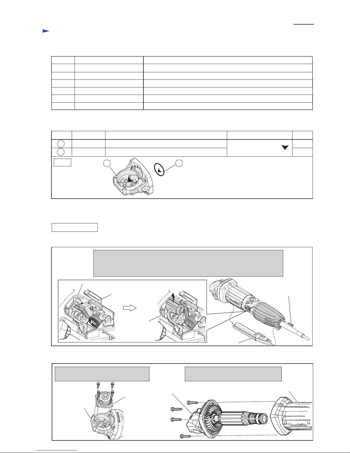
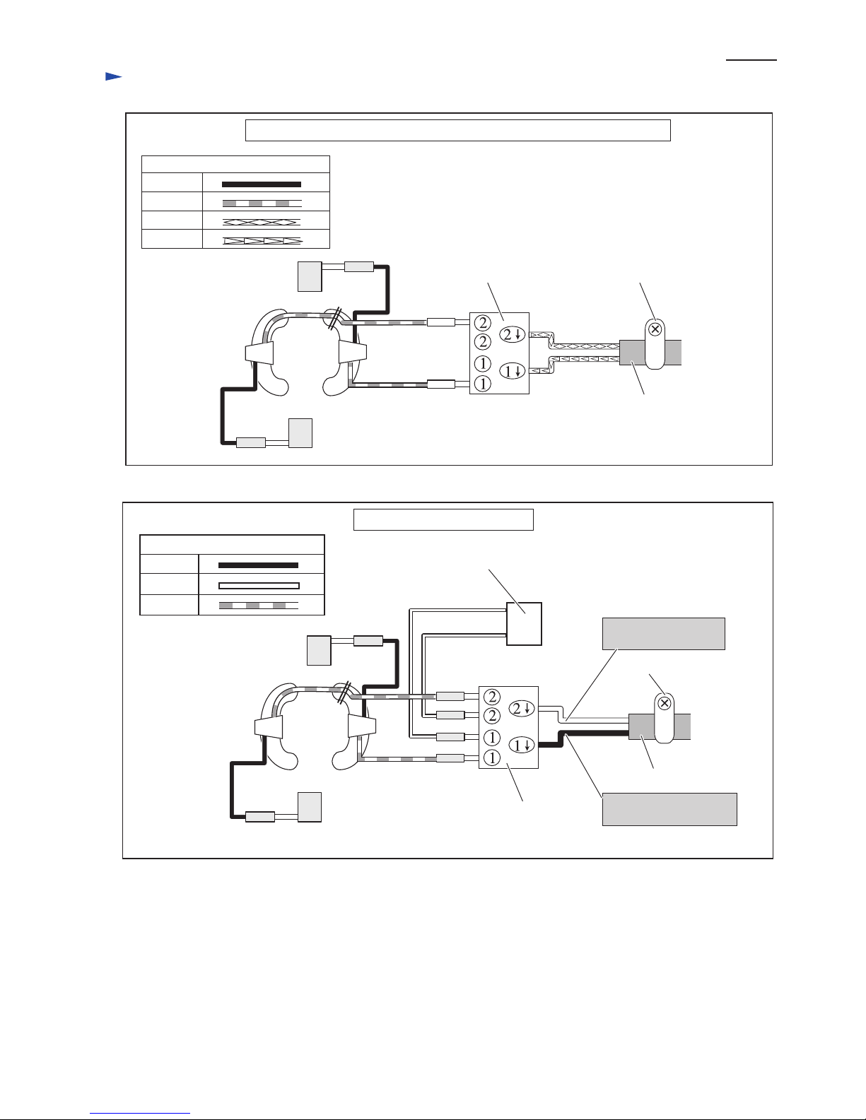
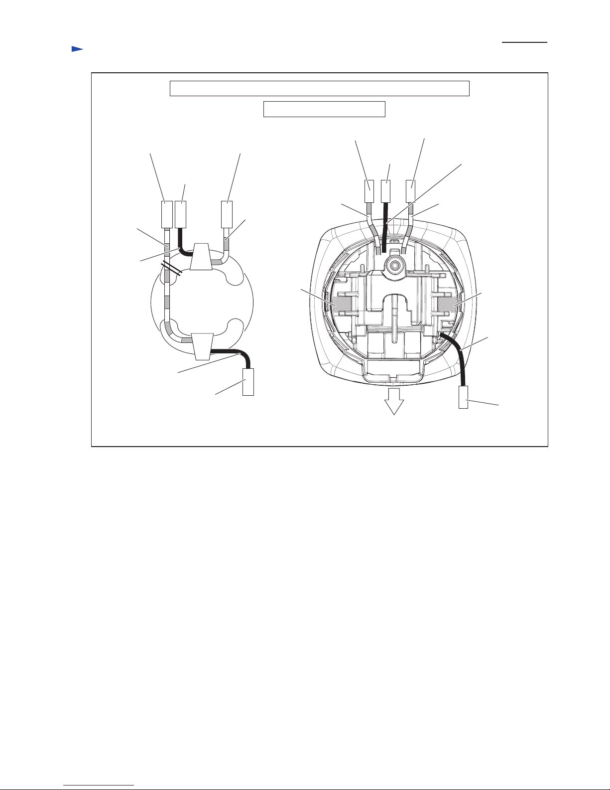
TECHNICAL INFORMATION

P 2/ 11
Repair
CAUTION: Repair the machine in accordance with “Instruction manual” or “Safety instructions”.
[1] NECESSARY REPAIRING TOOLS
[2] LUBRICATIONS
Fig. 1
Code No. Description Use for
1R004 Retaining ring S pliers ST-2 Removing / Assembling Ring spring 11
1R005 Retaining ring R pliers RT-2N Removing / Assembling Retaining ring R-32
1R006 Retaining ring R pliers RT-2E Removing / Assembling Retaining ring R-26
1R031 Bearing setting pipe 28-20.2 Removing Spiral bevel gear 37
1R268 Spring pin extractor M3 Disassembling Shaft lock
1R269 Bearing extractor Removing Ball bearing 696ZZ
Item No.
Apply the following lubricant to protect parts and product from unusual abrasion.
Description
O ring 26
Gear housing
Inner periphery
Gear room where Spiral bevel gears 37 and 10 rotate
9
18
Portion to lubricate Lubricant Amount
9
18 Makita grease SG.No.0 7g
a little
[3] DISASSEMBLY/ASSEMBLY
[3]-1. Armature, Ball bearing 629DDW, Ball bearing 607DDW, Spiral bevel gear 10
DISASSEMBLING
4x22 Tapping
screw (4pcs.)
M4x14 Pan
head screw (4pcs.)
Remove Motor housing from Gear housing
by loosening four 4x22 Tapping screws.
Remove Bearing box from Gear housing
by loosening four M4x14 Pan head screws.
Bearing box
Gear housing
Fig. 3
Gear housing
(2) Separate Bearing box from Gear housing, and then remove Motor housing. (Fig. 3)
Motor housing
Fig. 2
4x14 Tapping screw
Switch lever
A complete
1. Remove Rear cover by loosening 4x14 Tapping screw.
2. Remove Switch lever A complete.
3. Shift Spiral springs from the heads of Carbon brushes to the edges of Brush holders.
Then lift Carbon brushes so as to be detached from Armature’s commutator.
(1) After separating Rear cover from Motor housing, disconnect Carbon brushes from Armature’s commutator. (Fig. 2)
Carbon brush
Spiral spring
edge of
Brush holder

P 3/ 11
Repair
[3] DISASSEMBLY/ASSEMBLY
[3]-1. Armature, Ball bearing 629DDW, Ball bearing 607LLB, Spiral bevel gear 10 (cont.)
DISASSEMBLING
Fig. 4 Fig. 5
Wrench 10
M6 Hex nut Gear housing Spiral bevel
gear 10
Spiral bevel
gear 10
Armature
Gear housing
Armature
Pull out Armature from Gear housing
by hand while holding Spiral bevel
gear 10 carefully not to be dropped.
(3) Remove M6 Hex nut on Spiral bevel gear 10. (Fig. 4)
(4) Remove Armature from Gear housing. (Fig. 5)
Guide plate
1R006
Fig. 6 Fig. 7
(5) Ball bearing 629DDW can be removed as illustrated in Figs. 6 and 7.
Note: If the work mentioned in Fig. 7 is not successful, do the step mentioned in Fig. 8.
(6) Ball bearing 607LLB on Commutator end can be removed. (Fig. 9)
Strike Gear housing against work table.
Note: Cover the work table with something soft to avoid
the damage on Gear housing before disassembling.
Ball bearing
629DDW
Ball bearing 629DDW
Retaining ring R-26
Remove Retaining ring
R-26 with 1R006.
Locking M6 Hex nut with Wrench 10,
turn Armature counterclockwise by hand.
Note: If the above work is very difficult
due to the seizing of Spiral bevel
gear 10, spray a lubricant between
Armature shaft and Spiral bevel
gear 10, then turn and pull Armature
while holding Spiral bevel gear 10
with pliers and a cloth.
Spiral bevel
gear 10
M6 Hex nut
Set Armature, Spiral bevel gear 10 and M6 Hex nut
in place temporarily.
Retaining ring R-26 remains removed. (Refer to Fig. 6.)
Tap the edge of Gear housing
with plastic hammer.
Ball bearing 629DDW comes
with Armature.
Fig. 8
Fig. 9
Ball bearing 607LLB
1R269
Remove Labyrinth
rubber ring 19.
Remove Ball bearing
607LLB with 1R269.
Remove Insulation washer.
Labyrinth
rubber ring 19
Insulation
washer

P 4/ 11
Repair
[3] DISASSEMBLY/ASSEMBLY
[3]-1. Armature, Ball bearing 629DDW, Ball bearing 607LLB, Spiral bevel gear 10 (cont.)
[3]-2. Spiral bevel gear 37, Ball bearing 696ZZ, Ball bearing 6201DDW
ASSEMBLING
Take the disassembling step in reverse.
Note: (1) Fit the groove of Guide plate to the protrusion on Gear housing. (Fig. 10)
(2) Pay attention to the direction of Labyrinth rubber ring 19 and Insulation washer. (Fig. 9)
(3) Gear housing has to be assembled to Motor housing so that Spindle installation side faces Switch lever A
complete side. (Fig. 11)
Fig. 10
Protrusion on
Gear housing
Groove of Guide plate
Fig. 11
Switch lever A completeSpindle
DISASSEMBLING
Note: It is not necessary to separate Gear housing from
Motor housing when replacing the parts in Bearing box.
(1) Separate Bearing box section from Gear housing. (Fig. 3)
Remove Ball bearing 696ZZ with 1R269 and then separate
Ring spring 11 from Spindle with 1R004. (Fig. 12)
(2) Spindle, Spiral bevel gear 37 and Labyrinth ring can be
removed as illustrated in Fig. 13.
(3) Remove Ball bearing 6201DDW from Bearing box as
illustrated in Fig. 14.
After removing Ball bearing 696ZZ with 1R269,
remove Ring spring 11 with 1R004 and slotted
screwdriver.
1R031
1R005
Retaining ring
R-32
Labyrinth ring
Spindle
Retaining
ring R-32
Ring spring 11
slotted screwdriver
1R004
Fig. 12
Fig. 13
Fig. 14
Spindle
Labyrinth ring
Bearing box
Spiral bevel gear 37
Ball Bearing 6201DDW
Flat washer 12
Remove Retaining ring R-32 with 1R005,
Then remove Ball bearing 6201DDW by
striking Bearing box against the work table.
Note: Cover the work table with something
soft to avoid the damage on Bearing
box before disassembling.
Press down Spindle
with Arbor press. Note: Ball bearing 6201DDW has damaged through
the process of disassembling. Do not reuse it.
Receive Labyrinth ring
on 1R031.
Ball bearing 696ZZ

P 5/ 11
Repair
ASSEMBLING
[3] DISASSEMBLY/ASSEMBLY
[3]-2. Spiral bevel gear 37, Ball bearing 6201DDW, Ball bearing 696ZZ
Fig. A
Retaining
ring R-32
1R005
(1) Assemble Bearing box section in the order of Figs. A, Band D.
(2) Assemble Bearing box section to Gear housing.
Assembling Flat washer 12 and new Ball bearing 6201DDW to Bearing box.
And then secure them with Retaining ring R-32.
Correct Wrong
grooved side
Facing the flat surface to the upper side,
put Labyrinth ring onto 1R031 and
assemble Spindle.
Labyrinth ring works as a shield against
dust.
If Labyrinth ring is assembled to Spindle
facing the groove surface to the upper side,
it does not work as a shield against dust.
flat side
Fig. B Fig. C
Spiral bevel
gear 37
Bearing box
Ball bearing 696ZZ
Ring spring 11
Note: Ring spring 11 is deformed when removing.
Correct it with pliers after setting it to the groove
of Spindle.
Spindle
Assemble Spindle to Bearing
box by pressing with Arbor
press.
Assemble Spiral bevel
gear 37 by pressing
with Arbor press.
Assemble Ring spring 11 and Ball bearing 696ZZ
to Spindle.
Labyrinth ring
Fig. D
Spindle
New
Ball bearing
6201DDW
Flat washer 12
Bearing Box

P 7/ 11
Repair
DISASSEMBLING
[3] DISASSEMBLY/ASSEMBLY
[3]-3. Shaft lock
Fig. 17
Applying 1R268 to Shoulder pin 4 through the hole on Pin cap,
strike 1R268 with Hammer.
Shoulder pin 4 comes out from Gear housing complete.
Slowly release 1R268 from Pin cap
carefully not to lose Compression
spring 8.
Shoulder pin 4
Pin cap
Impossible to reuse Pin cap because removal
of Shoulder pin 4 damages the inside surface of
Pin cap, producing plastic dust.
Pin cap
Pin cap
Compression
spring 8
1R268
Shaft lock can be disassembled as illustrated in Figs.15 and 16.
1R350
Fig. 16
Fig. 15
ASSEMBLING
Fig. 18
(1) Be sure to use a new Pin cap for replacement and to remove all the plastic dust on Shoulder pin 4. (Fig. 17)
(2) Assemble the Parts for Shaft lock mechanism as illustrated in Fig. 18.
Plastic dust
O ring 4
Shoulder pin 4
Shoulder
pin 4
Assemble Pin cap by pressing it
to Shoulder pin 7.
Insert Shoulder pin 4 through the hole
of Gear housing complete.
Pin cap
Compression spring 8

P 7/ 11
Repair
[3] DISASSEMBLY/ASSEMBLY
[3]-4. Tips on removing of Field
Fig. 19 Fig. 21
Fig. 20
Note: Cracks may be happened to the edges of Motor housing by tapping with plastic hammer. Therefore, do not tap
the edges of Motor housing.
Disconnect Field lead wires and remove Armature from Motor housing.
(1) After disassemble Baffle plate and two 4x70 Tapping screws (Fig. 19), assemble Gear housing to Motor housing
temporarily.
(2) Tap the front portion of Gear housing with plastic hammer until Field moves half from the original position. (Fig. 20)
(3) After removing Gear housing, set two 4x22 Tapping screws to Motor housing and then tap the screws’ heads carefully
and alternately. (Fig. 21)
Baffle plate
Edge of Motor
housing (to match
with Gear housing)
Do not tap the portion.
4x70 Tapping Screw Motor housing
4x22 Tapping screw
(4pcs. temporarily setting)
Gear housing
Field
Field

P 8/ 11
Circuit diagram
Fig. D-1
Strain relief
Field viewed
from Rear cover
side
Brush holder
Brush holder
Switch
Power supply cord
Red
Color index of lead wires' sheath
Black
Brown
Blue
AC/DC Switch models (for Keppel corporation limited in Singapore, etc.)
Fig. D-2
Strain relief
Brown lead wire is used
for some countries.
Blue lead wire is used
for some countries.
Noise suppressor
Field viewed
from Rear cover
side
Brush holder
Switch
Power supply cord
Except AC/DC switch models
White
Red
Color index of lead wires' sheath
Black

P 9/ 11
Wiring diagram
Except AC/DC switch models
Field viewed
from Rear cover
side
to Switch
to Brush holder
Brush
holder Brush holder
to Brush holder
to Switch
Fig. D-3
AC/DC Switch models (for Keppel comporation limited in Singapore, etc.)
to Switch
Field lead
wire (red)
Field lead
wire (red)
Field lead
wire (red)
Field lead
wire (black)
Field lead
wire (black)
Field lead wire (red)
Field lead
wire (black)
to Switch
to Brush
holder
to Brush
holder
Switch Lever A
complete side
Field lead
wire (black)

Wiring diagram
P 10/ 11
Fig. D-4
Motor housing
(Back side view)
Connect Field lead wires
(red) to Switch, bending
them to inside at the
connecting portion to
Receptacle.
Field lead wires (red, black) have to be tight in Motor housing.
Field Lead wire (red)
Switch
Receptacle
Put sag portion of Field lead wires in this area.
Motor housing
Motor housing
(Right side view)
Motor housing
(Belly side view)
Rib A
Rib
Switch
Power supply cord
Rib B
Field lead wires (red, black) have
to be tight in Motor housing.
Brush
holder
Pass Field lead wire (black)
by Rib on Brush holder side.
Edge of Rib B
Motor housing
AC / DC Switch models (for Keppel corporation limited in Singapore, etc.)
1) Separate Lead wires (blue, brown)
of Power supply cord with Rib A.
2) Put the extra portions of Lead
wires (blue, brown) of Power
supply cord in this space so as
not to contact Rib B

Wiring diagram
P 11/ 11
Fig. D-5
Except AC/DC switch models
Motor housing
(Right side view)
Noise suppressor
(if used)
Brush holder
Rib
Rib
Motor housing
(Belly side view)
edge of Rib B
1) Separate Lead wires (black, white)
of Power supply cord with Rib A.
2) Put the extra portions of Lead
wires (black, white) of Power
supply cord in this space so as not
to contact Rib B. Rib B
Rib A
Switch
Power supply
cord
Field lead wires (red, black) have
to be tight in Motor housing.
Motor housing
Pass Field lead wire (black) by
Rib on the Brush holder side.
Motor housing
(Back side view)
Noise
Suppressor Rib
Boss
Put the extra portions of Field lead wires
and Noise suppressor lead wires in this
area.
Face the wire side of Noise suppressor to
Motor housing, put Noise suppressor into
the space surrounded by Ribs and Boss.
Field lead wires (red, black) have
to be tight in Motor housing.
Motor housing
Other manuals for GA4034
6
This manual suits for next models
2
Table of contents
Other Makita Grinder manuals

Makita
Makita GA7030 User manual

Makita
Makita 9558PB Quick start guide

Makita
Makita 9005BY User manual

Makita
Makita GA5020 User manual

Makita
Makita 9015DB User manual

Makita
Makita maktec MT967 User manual

Makita
Makita GA7080 User manual

Makita
Makita 906 User manual

Makita
Makita GA035G User manual

Makita
Makita Angle Grinder User manual

Makita
Makita 9560 User manual

Makita
Makita 9015DB Manual

Makita
Makita GA5010Y User manual

Makita
Makita GA9040SF01 User manual

Makita
Makita 9565PC Quick start guide

Makita
Makita DGA419 User manual

Makita
Makita DGD800 User manual

Makita
Makita GA4552 User manual

Makita
Makita GA036G User manual

Makita
Makita M0920 User manual