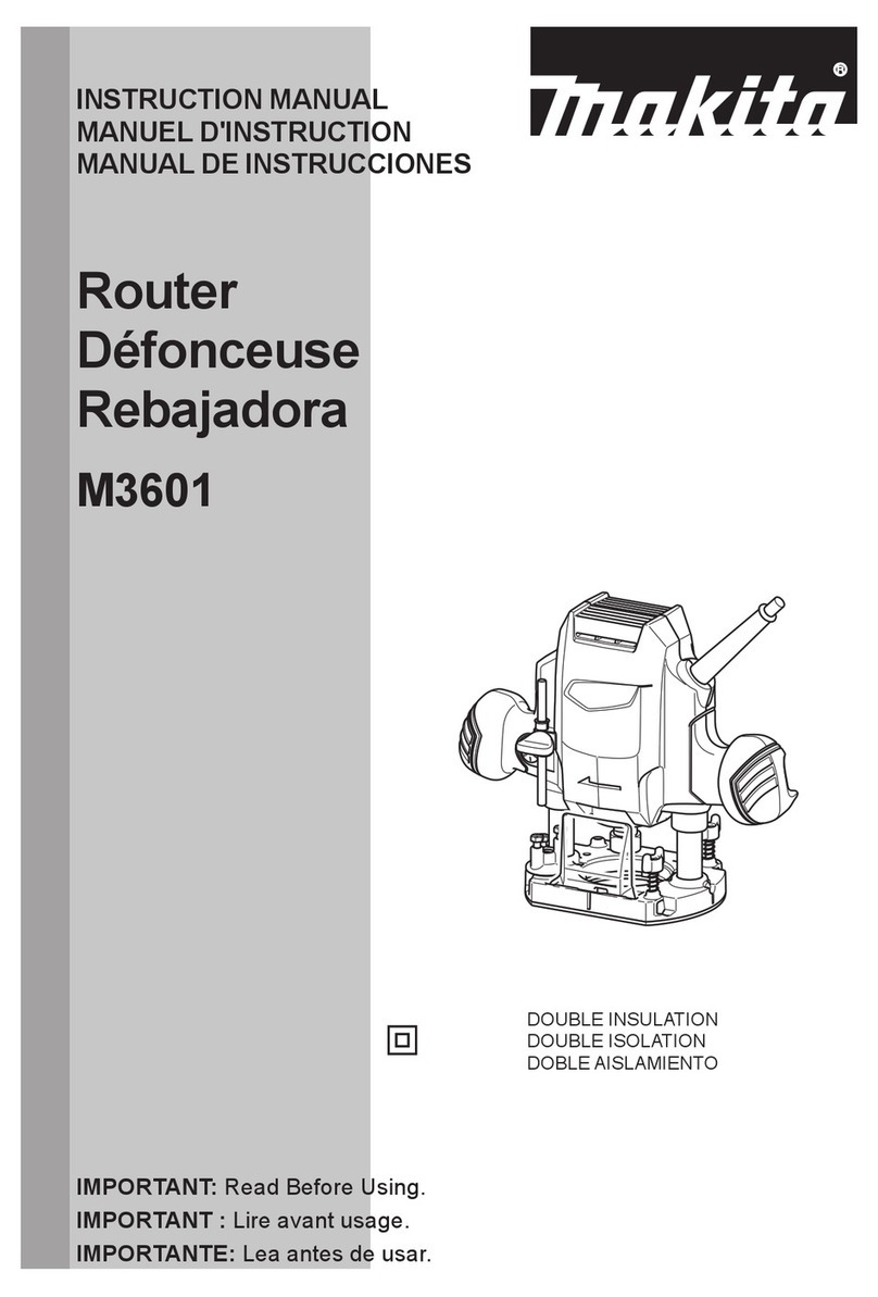
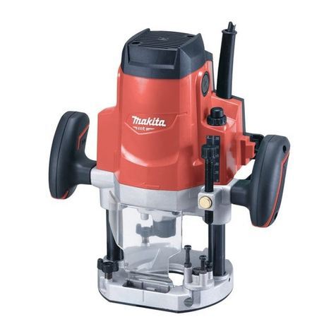
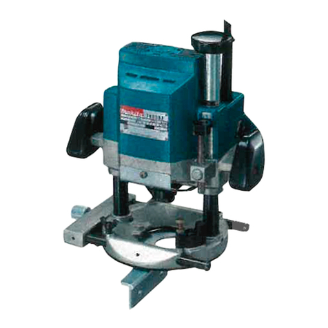
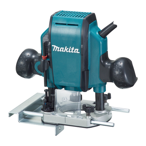
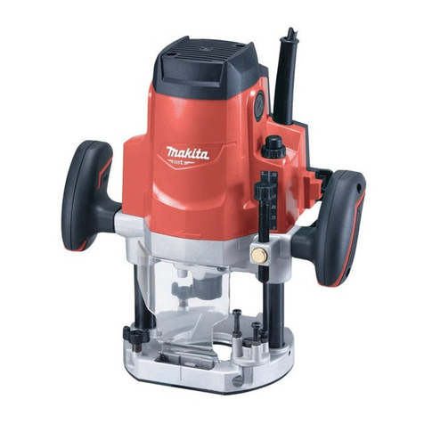
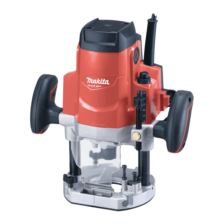
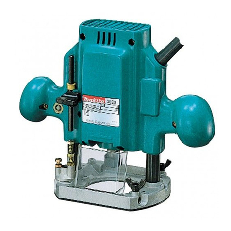
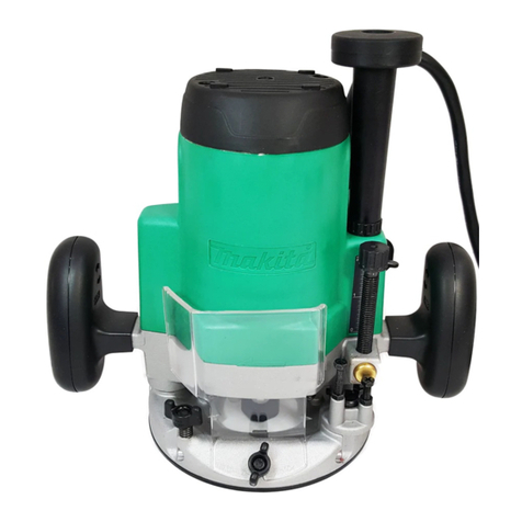
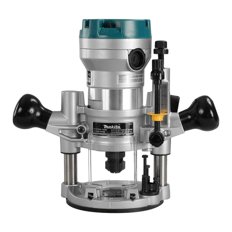
Makita M3600 User manual

INSTRUCTION MANUAL
MANUEL D'INSTRUCTION
MANUAL DE INSTRUCCIONES
Router
Défonceuse
Rebajadora
M3600
IMPORTANT: Read Before Using.
IMPORTANT : Lire avant usage.
IMPORTANTE: Lea antes de usar.
DOUBLE INSULATION
DOUBLE ISOLATION
DOBLE AISLAMIENTO

2ENGLISH
ENGLISH (Original instructions)
SPECIFICATIONS
Model: M3600
Collet chuck capacity 12.7 mm (1/2″)
Plunge capacity 0 - 60 mm (0 - 2-3/8″)
No load speed (RPM) 22,000 /min
Overall height 300 mm (11-3/4″)
Net weight 5.5 kg (12.2 lbs)
Safety class /II
• Due to our continuing program of research and development, the specications herein are subject to change
without notice.
• Specications may differ from country to country.
• Weight according to EPTA-Procedure 01/2003
General power tool safety warnings
WARNING: Read all safety warnings and
all instructions. Failure to follow the warnings and
instructions may result in electric shock, re and/or
serious injury.
Save all warnings and instruc-
tions for future reference.
The term "power tool" in the warnings refers to your
mains-operated (corded) power tool or battery-operated
(cordless) power tool.
Work area safety
1. Keep work area clean and well lit. Cluttered or
dark areas invite accidents.
2. Do not operate power tools in explosive atmo-
spheres, such as in the presence of ammable
liquids, gases or dust. Power tools create sparks
which may ignite the dust or fumes.
3. Keep children and bystanders away while
operating a power tool. Distractions can cause
you to lose control.
Electrical Safety
1. Power tool plugs must match the outlet. Never
modify the plug in any way. Do not use any
adapter plugs with earthed (grounded) power
tools. Unmodied plugs and matching outlets will
reduce risk of electric shock.
2. Avoid body contact with earthed or grounded
surfaces such as pipes, radiators, ranges and
refrigerators. There is an increased risk of elec-
tric shock if your body is earthed or grounded.
3. Do not expose power tools to rain or wet con-
ditions. Water entering a power tool will increase
the risk of electric shock.
4. Do not abuse the cord. Never use the cord for
carrying, pulling or unplugging the power tool.
Keep cord away from heat, oil, sharp edges
or moving parts. Damaged or entangled cords
increase the risk of electric shock.
5. When operating a power tool outdoors, use an
extension cord suitable for outdoor use. Use of
a cord suitable for outdoor use reduces the risk of
electric shock.
6. If operating a power tool in a damp location is
unavoidable, use a ground fault circuit inter-
rupter (GFCI) protected supply. Use of a GFCI
reduces the risk of electric shock.
Personal Safety
1. Stay alert, watch what you are doing and use
common sense when operating a power tool.
Do not use a power tool while you are tired or
under the inuence of drugs, alcohol or med-
ication. A moment of inattention while operating
power tools may result in serious personal injury.
2. Use personal protective equipment. Always
wear eye protection. Protective equipment such
as dust mask, non-skid safety shoes, hard hat, or
hearing protection used for appropriate conditions
will reduce personal injuries.
3. Prevent unintentional starting. Ensure the
switch is in the off-position before connecting
to power source and/or battery pack, picking
up or carrying the tool. Carrying power tools with
your nger on the switch or energising power tools
that have the switch on invites accidents.
4. Remove any adjusting key or wrench before
turning the power tool on. A wrench or a key left
attached to a rotating part of the power tool may
result in personal injury.
5. Do not overreach. Keep proper footing and
balance at all times. This enables better control
of the power tool in unexpected situations.
6. Dress properly. Do not wear loose clothing or
jewellery. Keep your hair, clothing, and gloves
away from moving parts. Loose clothes, jewel-
lery or long hair can be caught in moving parts.
7. If devices are provided for the connection of
dust extraction and collection facilities, ensure
these are connected and properly used. Use of
dust collection can reduce dust-related hazards.
Power tool use and care
1.
Do not force the power tool. Use the correct power tool
for your application. The correct power tool will do the job
better and safer at the rate for which it was designed.
3ENGLISH
2. Do not use the power tool if the switch does
not turn it on and off. Any power tool that cannot
be controlled with the switch is dangerous and
must be repaired.
3. Disconnect the plug from the power source
and/or the battery pack from the power tool
before making any adjustments, changing
accessories, or storing power tools. Such pre-
ventive safety measures reduce the risk of starting
the power tool accidentally.
4. Store idle power tools out of the reach of chil-
dren and do not allow persons unfamiliar with
the power tool or these instructions to operate
the power tool. Power tools are dangerous in the
hands of untrained users.
5. Maintain power tools. Check for misalignment
or binding of moving parts, breakage of parts
and any other condition that may affect the
power tool’s operation. If damaged, have the
power tool repaired before use. Many accidents
are caused by poorly maintained power tools.
6. Keep cutting tools sharp and clean. Properly
maintained cutting tools with sharp cutting edges
are less likely to bind and are easier to control.
7. Use the power tool, accessories and tool bits
etc. in accordance with these instructions, tak-
ing into account the working conditions and
the work to be performed. Use of the power tool
for operations different from those intended could
result in a hazardous situation.
Service
1. Have your power tool serviced by a qualied
repair person using only identical replacement
parts. This will ensure that the safety of the power
tool is maintained.
2. Follow instruction for lubricating and chang-
ing accessories.
3. Keep handles dry, clean and free from oil and
grease.
USE PROPER EXTENSION CORD. Make sure your
extension cord is in good condition. When using an
extension cord, be sure to use one heavy enough to
carry the current your product will draw. An undersized
cord will cause a drop in line voltage resulting in loss of
power and overheating. Table 1 shows the correct size
to use depending on cord length and nameplate ampere
rating. If in doubt, use the next heavier gage. The
smaller the gage number, the heavier the cord.
Table 1: Minimum gage for cord
Ampere Rating Volts Total length of cord in feet
120V 25 ft. 50 ft. 100 ft. 150 ft.
220V - 240V 50 ft. 100 ft. 200 ft. 300 ft.
More Than Not More Than AWG
06–18 16 16 14
610 18 16 14 12
10 12 16 16 14 12
12 16 14 12 Not Recommended
Router safety warnings
1. Hold power tool by insulated gripping sur-
faces, because the cutter may contact its own
cord. Cutting a “live” wire may make exposed
metal parts of the power tool “live” and shock the
operator.
2. Use clamps or another practical way to secure
and support the workpiece to a stable plat-
form. Holding the work by your hand or against
the body leaves it unstable and may lead to loss of
control.
3. Wear hearing protection during extended
period of operation.
4. Handle the router bits very carefully.
5. Check the router bit carefully for cracks or
damage before operation. Replace cracked or
damaged bit immediately.
6. Avoid cutting nails. Inspect for and remove all
nails from the workpiece before operation.
7. Hold the tool rmly with both hands.
8. Keep hands away from rotating parts.
9. Make sure the router bit is not contacting the
workpiece before the switch is turned on.
10.
Before using the tool on an actual workpiece, let
it run for a while. Watch for vibration or wobbling
that could indicate improperly installed bit.
11. Be careful of the router bit rotating direction
and the feed direction.
12. Do not leave the tool running. Operate the tool
only when hand-held.
13. Always switch off and wait for the router bit to
come to a complete stop before removing the
tool from workpiece.
14. Do not touch the router bit immediately after
operation; it may be extremely hot and could
burn your skin.
15. Do not smear the tool base carelessly with
thinner, gasoline, oil or the like. They may
cause cracks in the tool base.
16. Use router bits of the correct shank diameter
suitable for the speed of the tool.
17. Some material contains chemicals which may
be toxic. Take caution to prevent dust inhala-
tion and skin contact. Follow material supplier
safety data.
18. Always use the correct dust mask/respirator
for the material and application you are work-
ing with.

4ENGLISH
SAVE THESE INSTRUCTIONS.
WARNING: DO NOT let comfort or familiarity
with product (gained from repeated use) replace
strict adherence to safety rules for the subject
product. MISUSE or failure to follow the safety
rules stated in this instruction manual may cause
serious personal injury.
Symbols
The followings show the symbols used for tool.
volts
amperes
hertz
alternating current
no load speed
Class II Construction
revolutions or reciprocation per minute
FUNCTIONAL
DESCRIPTION
CAUTION: Always be sure that the tool is
switched off and unplugged before adjusting or
checking function on the tool.
Adjusting the depth of cut
Place the tool on a at surface. Loosen the lock lever
and lower the tool body until the router bit just touches
the at surface. Press the lock lever down to lock the
tool body. While pressing the fast-feed button, move the
stopper pole up or down until the desired depth of cut is
obtained. Minute depth adjustments can be obtained by
turning the stopper pole (1.5 mm (1/16″) per turn).
1
2
3
4
5
6
Fig.1
► 1. Nylon nut 2. Stopper pole 3. Fast-feed button
4. Adjusting hex bolt 5. Stopper 6. Lock lever
CAUTION: The depth of cut should not be
more than 20 mm (13/16″) at a pass when cutting
grooves. For extra-deep grooving operations,
make two or three passes with progressively
deeper router bit settings.
Nylon nut
For tool without the knob
The upper limit of the tool body can be adjusted by
turning the nylon nut. Do not lower the nylon nut too low.
The router bit will protrude dangerously.
For tool with the knob
By turning the knob, the upper limit of the tool body can
be adjusted. When the tip of the router bit is retracted
more than required in relation to the base plate surface,
turn the knob to lower the upper limit. Do not lower the
knob too low. The router bit will protrude dangerously.
1
Fig.2
► 1. Knob
CAUTION: Since excessive cutting may cause
overload of the motor or difculty in controlling
the tool, the depth of cut should not be more than
20 mm (13/16″) at a pass when cutting grooves.
When you wish to cut grooves more than 20 mm
(13/16″) deep, make several passes with progres-
sively deeper router bit settings.
CAUTION: Do not lower the knob too low. The
router bit will protrude dangerously.

5ENGLISH
Stopper block
As the rotary stopper has three adjusting hex bolts, you
can easily obtain three different depths of cut without
readjusting the stopper pole. To adjust the hex bolts,
loosen the hex nuts on them and turn the hex bolts.
After obtaining the desired position, tighten the hex nuts
to secure the hex bolts.
1
2
3
4
5
Fig.3
► 1. Stopper pole 2. Chip deector 3. Stopper
4. Adjusting hex bolt 5. Hex nut
Switch action
CAUTION: Before plugging in the tool, always
check to see that the tool is switched off.
CAUTION: Make sure that the shaft lock is
released before the switch is turned on.
To start the tool, move the switch lever to the I position.
To stop the tool, move the switch lever to the O position.
1
Fig.4
► 1. Switch lever
CAUTION: Hold the tool rmly when turning
off the tool, to overcome the reaction.
ASSEMBLY
CAUTION: Always be sure that the tool is
switched off and unplugged before carrying out
any work on the tool.
Installing or removing the router bit
Insert the router bit all the way into the collet cone.
Press the shaft lock to keep the shaft stationary and
use the wrench to tighten the collet nut securely. When
using router bits with smaller shank diameter, rst insert
the appropriate collet sleeve into the collet cone, then
install the router bit as illustrated.
To remove the router bit, follow the installation proce-
dure in reverse.
1
2
Fig.5
► 1. Shaft lock 2. Wrench
CAUTION: Install the router bit securely.
Always use only the wrench provided with the
tool. A loose or overtightened router bit can be
dangerous.
CAUTION: Do not tighten the collet nut with-
out inserting a router bit or install small shank
bits without using a collet sleeve. Either can lead
to breakage of the collet cone.

6ENGLISH
OPERATION
CAUTION: Before operation, always make
sure that the tool body automatically rises to
the upper limit and the router bit does not pro-
trude from the tool base when the lock lever is
loosened.
CAUTION: Before operation, always make
sure that the chip deector is installed properly.
1
Fig.6
► 1. Chip deector
Set the tool base on the workpiece to be cut without
the router bit making any contact. Then turn the tool on
and wait until the router bit attains full speed. Lower the
tool body and move the tool forward over the workpiece
surface, keeping the tool base ush and advancing
smoothly until the cutting is complete.
When doing edge cutting, the workpiece surface should
be on the left side of the router bit in the feed direction.
1
2
3
4
4
2
Fig.7
► 1. Workpiece 2. Bit revolving direction 3. View from
the top of the tool 4. Feed direction
NOTE: Moving the tool forward too fast may cause
a poor quality of cut, or damage to the router bit or
motor. Moving the tool forward too slowly may burn
and mar the cut. The proper feed rate will depend on
the router bit size, the kind of workpiece and depth
of cut.
Before beginning the cut on the actual workpiece, it
is advisable to make a sample cut on a piece of scrap
lumber. This will show exactly how the cut will look as
well as enable you to check dimensions.
NOTE: When using the straight guide or the trimmer
guide, be sure to install it on the right side in the feed
direction. This will help to keep it ush with the side of
the workpiece.
1
23
4
Fig.8
► 1. Feed direction 2. Router bit revolving direction
3. Workpiece 4. Straight guide
Straight guide
The straight guide is effectively used for straight cuts
when chamfering or grooving.
Straight guide (Type A)
Optional accessory
Install the straight guide on the guide holder with the
thumb screw (B). Insert the guide holder into the holes
in the tool base and tighten the thumb screw (A). To
adjust the distance between the router bit and the
straight guide, loosen the thumb screw (B) and turn the
ne adjusting screw. At the desired distance, tighten the
thumb screw (B) to secure the straight guide in place.
1
2
B
3
A
Fig.9
► 1. Guide holder 2. Fine adjusting screw 3. Straight
guide

7ENGLISH
Straight guide (Type B)
Optional accessory
Insert the straight guide into the holes in the tool base
and tighten the thumb screw. To adjust the distance
between the router bit and the straight guide, loosen the
thumb screw. At the desired distance, tighten the thumb
screw to secure the straight guide in place.
Wider straight guide of desired dimensions may be
made by using the convenient holes in the guide to bolt
on extra pieces of wood.
1
2
Fig.10
► 1. Thumb screw 2. Straight guide
When using a large diameter router bit, attach pieces
of wood to the straight guide which have a thickness of
more than 15 mm (5/8″) to prevent the router bit from
striking the straight guide.
When cutting, move the tool with the straight guide ush
with the side of the workpiece.
C1
A
B
2
Fig.11
► 1. Straight guide 2. Wood
A=55 mm (2-3/16″)
B=55 mm (2-3/16″)
C=15 mm (5/8″) or thicker
Templet guide
The templet guide provides a sleeve through which the
router bit passes, allowing use of the tool with templet
patterns. To install the templet guide, loosen the screws
on the tool base, insert the templet guide and then
tighten the screws.
Fig.12
Secure the templet to the workpiece. Place the tool on
the templet and move the tool with the templet guide
sliding along the side of the templet.
1
2
3
Fig.13
► 1. Templet guide 2. Screws 3. Base plate
NOTE: The workpiece will be cut a slightly different
size from the templet. Allow for the distance (X)
between the router bit and the outside of the templet
guide. The distance (X) can be calculated by using
the following equation:
Distance (X) = (outside diameter of the templet
guide - router bit diameter) / 2
1
2
3
4
5
6
7
Fig.14
► 1. Router bit 2. Base 3. Templet 4. Workpiece
5. Distance (X) 6. Outside diameter of the templet
guide 7. Templet guide

8ENGLISH
Trimmer guide
Trimming, curved cuts in veneers for furniture and the
like can be done easily with the trimmer guide. The
guide roller rides the curve and assures a ne cut.
Trimmer guide (Type A)
Optional accessory
Install the trimmer guide on the guide holder with the
thumb screw (B). Insert the guide holder into the holes
in the tool base and tighten the thumb screw (A). To
adjust the distance between the router bit and the
trimmer guide, loosen the thumb screw (B) and turn the
ne adjusting screw. When adjusting the guide roller up
or down, loosen the thumb screw (C). After adjusting,
tighten all the thumb screws securely.
1
2
3
4
B
A
C
Fig.15
► 1. Guide holder 2. Fine adjusting screw 3. Trimmer
guide 4. Guide roller
Trimmer guide (Type B)
Optional accessory
Install the trimmer guide on the straight guide with the
thumb screws (B). Insert the straight guide into the
holes in the tool base and tighten the thumb screw (A).
To adjust the distance between the router bit and the
trimmer guide, loosen the thumb screws (B). When
adjusting the guide roller up or down, loosen the thumb
screw (C). After adjusting, tighten all the thumb screws
securely.
1
2
B
A
C
Fig.16
► 1. Guide roller 2. Trimmer guide
When cutting, move the tool with the guide roller riding
the side of the workpiece.
3
1
2
Fig.17
► 1. Router bit 2. Guide roller 3. Workpiece
Dust cover (For tool with the knob)
Optional accessory
Dust cover prevents sawdust from being drawn into the
tool in the inverted position.
Install the dust cover as illustrated when using the tool
with a router stand available in the market.
Remove it when using the tool in the normal position.
1
2
Fig.18
► 1. Screw 2. Dust cover
Spacer (For tool with the knob)
Optional accessory
The spacer prevents the router bit from dropping into
the chuck when replacing the router bit in the inverted
position.
Insert the spacer as illustrated when using the tool with
a router stand available in the market.
12
3
Fig.19
► 1. Collet nut 2. Collet cone 3. Spacer

9ENGLISH
Dust extraction
Optional accessory
Use the vacuum head for dust extraction.
1
Fig.20
► 1. Vacuum head
Installing the vacuum head
1
2
Fig.21
► 1. Support 2. Lock lever
1. Raise the lock lever of the vacuum head.
2. Place the vacuum head on the tool base so that its
top will be caught in the hook on the tool base.
3. Insert the supports on the vacuum head into the
hooks on the front of the tool base.
4. Push down the lock lever onto the tool base.
5. Connect a vacuum cleaner to the vacuum head.
Fig.22
Removing the vacuum head
1. Raise the lock lever.
2. Pull the vacuum head out of the tool base while
holding the supports between thumb and nger.
MAINTENANCE
CAUTION: Always be sure that the tool is
switched off and unplugged before attempting to
perform inspection or maintenance.
NOTICE: Never use gasoline, benzine, thinner,
alcohol or the like. Discoloration, deformation or
cracks may result.
Replacing carbon brushes
1
Fig.23
► 1. Limit mark
Check the carbon brushes regularly.
Replace them when they wear down to the limit mark.
Keep the carbon brushes clean and free to slip in the
holders. Both carbon brushes should be replaced at the
same time. Use only identical carbon brushes.
1. Use a screwdriver to remove the brush holder
caps.
2. Take out the worn carbon brushes, insert the new
ones and secure the brush holder caps.
1
Fig.24
► 1. Brush holder cap

10 ENGLISH
For tool with the knob
CAUTION: Be sure to re-install the knob after
inserting new carbon brush.
Release the lock lever and remove the knob by turning
it counterclockwise.
1
Fig.25
► 1. Knob
NOTE: The compression spring will come out of
the knob, so be careful not to lose the compression
spring.
To maintain product SAFETY and RELIABILITY,
repairs, any other maintenance or adjustment should
be performed by Makita Authorized or Factory Service
Centers, always using Makita replacement parts.
OPTIONAL
ACCESSORIES
Router bits
Straight bit
Fig.26
Unit:mm
D A L1 L2
620 50 15
1/4″
D A L1 L2
12 12 60 30
1/2″
12 10 60 25
1/2″
8 8 60 25
6 8 50 18
1/4″
6 6 50 18
1/4″
“U”Grooving bit
R
Fig.27
Unit:mm
D A L1 L2 R
6 6 50 18 3
“V”Grooving bit
Fig.28
Unit:mm
D A L1 L2 θ
1/4″ 20 50 15 90°

11 ENGLISH
Dovetail bit
Fig.29
Unit:mm
D A L1 L2 θ
814.5 55 10 35°
3/8″
814.5 55 14.5 23°
3/8″
812 50 930°
3/8″
Drill point ush trimming bit
Fig.30
Unit:mm
D A L1 L2 L3
12 12 60 20 35
8 8 60 20 35
6 6 60 18 28
Drill point double ush trimming bit
Fig.31
Unit:mm
D A L1 L2 L3 L4
6 6 70 40 12 14
Slotting cutter
Fig.32
Unit:mm
D A L1 L2
12 30 55 6
1/2″
12 30 55 3
1/2″

12 ENGLISH
Board-jointing bit
Fig.33
Unit:mm
DA1 A2 L1 L2 L3
12 38 27 61 420
Corner rounding bit
Fig.34
Unit:mm
DA1 A2 L1 L2 L3 R
625 948 13 5 8
620 845 10 4 4
Chamfering bit
Fig.35
Unit:mm
DA1 A2 L1 L2 L3 C
12 30 20 55 12 20 4
1/2″
Fig.36
Unit:mm
D A L1 L2 L3 θ
623 46 11 630°
620 50 13 545°
620 49 14 260°
Beading bit
Fig.37

13 ENGLISH
Unit:mm
DA1 A2 L1 L2 L3 R
12 30 20 55 12 20 4
1/2″
Cove beading bit
Fig.38
Unit:mm
D A L1 L2 R
620 43 8 4
625 48 13 8
Ball bearing ush trimming bit
Fig.39
Unit:mm
D A L1 L2
610 50 20
1/4″
Ball bearing corner rounding bit
Fig.40
Unit:mm
DA1 A2 L1 L2 L3 R
615 837 73.5 3
621 840 10 3.5 6
1/4″ 21 840 10 3.5 6
Ball bearing chamfering bit
Fig.41
Unit:mm
DA1 A2 L1 L2 θ
626 842 12 45°
1/4″
620 841 11 60°
Ball bearing beading bit
Fig.42

14 ENGLISH
Unit:mm
DA1 A2 A3 L1 L2 L3 R
620 12 840 10 5.5 4
626 12 842 12 4.5 7
Ball bearing cove beading bit
Fig.43
Unit:mm
DA1 A2 A3 A4 L1 L2 L3 R
620 18 12 840 10 5.5 3
626 22 12 842 12 5 5
Ball bearing roman ogee bit
Fig.44
Unit:mm
DA1 A2 L1 L2 L3 R1 R2
620 840 10 4.5 2.5 4.5
626 842 12 4.5 3 6
Double ball bearing round corner bit
Fig.45
Unit:mm
DA1 A2 A3 L1 L2 L3 R
12 35 27 19 70 11 3.5 3
1/2″
MAKITA LIMITED ONE YEAR
WARRANTY
Warranty Policy
Every Makita tool is thoroughly inspected and tested
before leaving the factory. It is warranted to be free of
defects from workmanship and materials for the period
of ONE YEAR from the date of original purchase.
Should any trouble develop during this one year period,
return the COMPLETE tool, freight prepaid, to one
of Makita’s Factory or Authorized Service Centers. If
inspection shows the trouble is caused by defective
workmanship or material, Makita will repair (or at our
option, replace) without charge.
This Warranty does not apply where:
• repairs have been made or attempted by others:
• repairs are required because of normal wear and
tear:
• the tool has been abused, misused or improperly
maintained:
• alterations have been made to the tool.
IN NO EVENT SHALL MAKITA BE LIABLE FOR ANY
INDIRECT, INCIDENTAL OR CONSEQUENTIAL
DAMAGES FROM THE SALE OR USE OF THE
PRODUCT. THIS DISCLAIMER APPLIES BOTH
DURING AND AFTER THE TERM OF THIS
WARRANTY.
MAKITA DISCLAIMS LIABILITY FOR ANY IMPLIED
WARRANTIES, INCLUDING IMPLIED WARRANTIES
OF "MERCHANTABILITY" AND "FITNESS FOR A
SPECIFIC PURPOSE," AFTER THE ONE YEAR TERM
OF THIS WARRANTY.
This Warranty gives you specic legal rights, and you
may also have other rights which vary from state to
state. Some states do not allow the exclusion or lim-
itation of incidental or consequential damages, so the
above limitation or exclusion may not apply to you.
Some states do not allow limitation on how long an
implied warranty lasts, so the above limitation may not
apply to you.

15 FRANÇAIS
FRANÇAIS (Mode d’emploi original)
SPÉCIFICATIONS
Modèle : M3600
Capacité du mandrin à pince 12,7 mm (1/2″)
Capacité de plongée 0 - 60 mm (0 - 2-3/8″)
Vitesse à vide (T/MIN) 22 000 /min
Hauteur hors-tout 300 mm (11-3/4″)
Poids net 5,5 kg (12,2 lbs)
Classe de sécurité /II
• Étant donné l’évolution constante de notre programme de recherche et de développement, les spécications
contenues dans ce manuel sont sujettes à modication sans préavis.
• Les spécications peuvent varier suivant les pays.
• Poids conforme à la procédure EPTA du 01/2003
Consignes de sécurité générales
pour outils électriques
MISE EN GARDE : Lisez toutes les
consignes de sécurité et toutes les instructions.
L’ignorance des mises en garde et des instructions
comporte un risque de choc électrique, d’incendie et/
ou de blessure grave.
Conservez toutes les mises en
garde et instructions pour réfé-
rence future.
Le terme « outil électrique » qui gure dans les avertis-
sements fait référence à un outil électrique branché sur
une prise de courant (par un cordon d’alimentation) ou
alimenté par batterie (sans l).
Sécurité de la zone de travail
1. Maintenez la zone de travail propre et bien
éclairée. Les zones de travail encombrées ou
sombres ouvrent grande la porte aux accidents.
2. N’utilisez pas les outils électriques dans les
atmosphères explosives, par exemple en pré-
sence de liquides, gaz ou poussières inam-
mables. Les outils électriques produisent des
étincelles au contact desquelles la poussière ou
les vapeurs peuvent s’enammer.
3. Assurez-vous qu’aucun enfant ou curieux ne
s’approche pendant que vous utilisez un outil
électrique. Vous risquez de perdre la maîtrise de
l’outil si votre attention est détournée.
Sécurité en matière d’électricité
1. Les ches d’outil électrique sont conçues pour
s’adapter parfaitement aux prises de courant.
Ne modiez jamais la che de quelque façon
que ce soit. N’utilisez aucun adaptateur de
che sur les outils électriques avec mise à
la terre. En ne modiant pas les ches et en les
insérant dans des prises de courant pour les-
quelles elles ont été conçues, vous réduirez les
risques de choc électrique.
2. Évitez tout contact corporel avec les surfaces
mises à la terre, telles que tuyaux, radiateurs,
cuisinières et réfrigérateurs. Le risque de choc
électrique est plus élevé si votre corps se trouve
mis à la terre.
3. N’exposez pas les outils électriques à la pluie
ou à l’eau. La présence d’eau dans un outil élec-
trique augmente le risque de choc électrique.
4. Ne maltraitez pas le cordon. N’utilisez jamais
le cordon pour transporter, tirer ou débrancher
l’outil électrique. Maintenez le cordon à l’écart
des sources de chaleur, de l’huile, des objets à
bords tranchants et des pièces en mouvement.
Le risque de choc électrique est plus élevé lorsque
les cordons sont endommagés ou enchevêtrés.
5. Lorsque vous utilisez un outil électrique à l’ex-
térieur, utilisez un cordon prolongateur conçu
pour l’usage extérieur. Les risque de choc élec-
trique est moindre lorsqu’un cordon conçu pour
l’usage extérieur est utilisé.
6. Si vous devez utiliser un outil électrique dans
un endroit humide, utilisez une source d’ali-
mentation protégée par un disjoncteur de fuite
à la terre. L’utilisation d’un disjoncteur de fuite à la
terre réduit le risque de choc électrique.
Sécurité personnelle
1. Restez alerte, attentif à vos mouvements et
faites preuve de bon sens lorsque vous utili-
sez un outil électrique. N’utilisez pas les outils
électriques si vous êtes fatigué ou avez pris
une drogue, de l’alcool ou un médicament. Un
moment d’inattention pendant l’utilisation d’un
outil électrique peut entraîner une grave blessure.
2. Portez des dispositifs de protection person-
nelle. Portez toujours une protection oculaire.
Les risques de blessure seront moins élevés si
vous utilisez des dispositifs de protection tels
qu’un masque anti-poussière, des chaussures à
semelle antidérapante, une coiffure résistante ou
une protection d’oreilles.

16 FRANÇAIS
3. Évitez les démarrages accidentels. Assurez-
vous que l’interrupteur est en position d’arrêt
avant de brancher l’outil à la prise de courant
et/ou au bloc-piles, et avant de prendre ou
de transporter l’outil. Vous ouvrez la porte aux
accidents si vous transportez les outils électriques
avec le doigt sur l’interrupteur ou si vous les bran-
chez alors que l’interrupteur est en position de
marche.
4. Retirez toute clé de réglage ou de serrage
avant de mettre l’outil électrique sous tension.
Toute clé laissée en place sur une pièce rotative
de l’outil électrique peut entraîner une blessure.
5. Ne vous étirez pas exagérément. Assurez-vous
d’une bonne prise au sol et d’un bon équilibre
en tout temps. Cela vous permettra d’avoir une
meilleure maîtrise de l’outil électrique dans les
situations imprévues.
6. Portez des vêtements adéquats. Ne portez ni
vêtements amples ni bijoux. Vous devez main-
tenir cheveux, vêtements et gants à l’écart des
pièces en mouvement. Les pièces en mouve-
ment peuvent happer les vêtements amples, les
bijoux et les cheveux longs.
7. Si des accessoires sont fournis pour raccorder
un appareil d’aspiration et de collecte de la
poussière, assurez-vous qu’ils sont correc-
tement raccordés et qu’ils sont utilisés de
manière adéquate. L’utilisation d’un appareil de
collecte permet de réduire les risques liés à la
présence de poussière dans l’air.
Utilisation et entretien des outils électriques
1. Ne forcez pas l’outil électrique. Utilisez l’outil
électrique adéquat suivant le type de travail à
effectuer. Si vous utilisez l’outil électrique adé-
quat et respectez le régime pour lequel il a été
conçu, il effectuera un travail de meilleure qualité
et plus sécuritaire.
2. N’utilisez pas l’outil électrique s’il n’est pas
possible de l’allumer et de l’éteindre avec son
interrupteur. Un outil électrique dont l’interrupteur
est défectueux représente un danger et doit être
réparé.
3. Débranchez la che de la source d’alimen-
tation et/ou retirez le bloc-piles de l’outil
électrique avant d’effectuer tout réglage, de
remplacer un accessoire ou de ranger l’ou-
til électrique. De telles mesures préventives
réduisent les risques de démarrage accidentel de
l’outil électrique.
4. Après l’utilisation d’un outil électrique,
rangez-le hors de portée des enfants et ne
laissez aucune personne l’utiliser si elle n’est
pas familiarisée avec l’outil électrique ou les
présentes instructions d’utilisation. Les outils
électriques représentent un danger entre les
mains de personnes qui n’en connaissent pas le
mode d’utilisation.
5. Veillez à l’entretien des outils électriques.
Assurez-vous que les pièces mobiles ne sont
pas désalignées ou coincées, qu’aucune pièce
n’est cassée et que l’outil électrique n’a subi
aucun dommage affectant son bon fonction-
nement. Le cas échéant, faites réparer l’outil
électrique avant de l’utiliser. De nombreux
accidents sont causés par des outils électriques
mal entretenus.
6. Maintenez les outils tranchants bien aiguisés
et propres. Un outil tranchant dont l’entretien est
effectué correctement et dont les bords sont bien
aiguisés risquera moins de se coincer et sera plus
facile à maîtriser.
7. Utilisez l’outil électrique, ses accessoires, ses
embouts, etc., en respectant les présentes
instructions, en tenant compte des conditions
de travail et du type de travail à effectuer.
L’utilisation d’un outil électrique pour d’autres
usages que ceux prévus peut entraîner une situa-
tion dangereuse.
Réparation
1. Faites réparer votre outil électrique par un
réparateur qualié qui utilise des pièces de
rechange identiques aux pièces d’origine. Le
maintien de la sûreté de l’outil électrique sera ainsi
assuré.
2. Suivez les instructions de lubrication et de
remplacement des accessoires.
3. Maintenez les poignées de l’outil sèches,
propres et exemptes d’huile ou de graisse.
UTILISEZ UN CORDON PROLONGATEUR
APPROPRIÉ. Assurez-vous que votre cordon prolon-
gateur est en bonne condition. Lorsque vous utilisez
un cordon prolongateur, assurez-vous qu’il est assez
robuste pour transporter le courant exigé par le produit.
Un cordon trop petit entraînera une baisse dans la
tension composée, ce qui causera une perte d’énergie
et une surchauffe. Le tableau 1 indique la dimension de
cordon à utiliser, en fonction de la longueur du cordon
et de l’intensité nominale gurant sur la plaque signalé-
tique. En cas de doute, utilisez un calibre plus robuste.
Plus le numéro de calibre est bas, plus le cordon est
robuste.
Tableau 1 : Calibre minimum du cordon
Intensité nominale Volts Longueur totale du cordon en pieds
120 V 25 ft. 50 ft. 100 ft. 150 ft.
220 V - 240 V 50 ft. 100 ft. 200 ft. 300 ft.
Plus de Pas plus de Calibre américain des ls
06–18 16 16 14
610 18 16 14 12
10 12 16 16 14 12
12 16 14 12 Non recommandé

17 FRANÇAIS
Consignes de sécurité pour
défonceuse
1. Tenez l’outil électrique par ses surfaces de
prise isolées, car l’accessoire tranchant peut
entrer en contact avec le cordon de l’outil. Si
l’outil électrique coupe un l sous tension, ses par-
ties métalliques exposées peuvent se mettre sous
tension et transmettre une décharge électrique à
l’utilisateur.
2. Utilisez des dispositifs de serrage ou autre
moyen pratique pour xer et soutenir la pièce
sur une surface stable. La pièce sera instable si
vous la tenez d’une main ou contre votre corps, et
vous risquez de perdre le contrôle de l’outil.
3. Lors d’une utilisation prolongée, portez une
protection d’oreilles.
4. Manipulez les embouts pour défonceuse très
prudemment.
5. Avant de commencer le travail, vériez soi-
gneusement l’absence de ssures ou de
dommages sur l’embout pour défonceuse.
Remplacez immédiatement tout embout s-
suré ou endommagé.
6. Prenez garde aux clous. Inspectez la pièce et
retirez-en tous les clous avant de commencer
le travail.
7. Tenez l’outil fermement à deux mains.
8. Gardez les mains à l’écart des pièces en
rotation.
9. Avant d’allumer l’outil, assurez-vous que l’em-
bout pour défonceuse ne touche pas la pièce à
travailler.
10. Avant d’utiliser l’outil sur la pièce à travailler,
laissez-le tourner un instant. Vériez l’absence
de vibrations ou d’oscillations, car ces symp-
tômes peuvent indiquer que l’embout est mal
installé.
11. Observez bien le sens de rotation de l’embout
pour défonceuse, et le sens de progression.
12. Ne quittez pas l’outil pendant qu’il tourne.
N’utilisez l’outil qu’une fois que vous l’avez
bien en main.
13. Avant de retirer l’outil de la pièce à travailler,
éteignez-le toujours et attendez l’arrêt complet
de l’embout pour défonceuse.
14. Ne touchez pas l’embout pour défonceuse
immédiatement après l’utilisation; il peut être
extrêmement chaud et vous brûler la peau.
15. Ne laissez pas négligemment la base de l’outil
s’imprégner de diluant, d’essence, d’huile, etc.
Ces produits peuvent provoquer des ssures
sur la base de l’outil.
16. Utilisez des embouts pour défonceuse dont le
diamètre de la tige est adéquat et adapté à la
vitesse de l’outil.
17. Certains matériaux contiennent des produits
chimiques qui peuvent être toxiques. Prenez
les précautions nécessaires pour éviter l’in-
halation des poussières et le contact avec la
peau. Respectez les données de sécurité du
fournisseur du matériau.
18.
Portez toujours un masque antipoussières ou un
respirateur adapté au matériau et à l’outil utilisés.
CONSERVEZ CE MODE
D’EMPLOI.
MISE EN GARDE : NE VOUS LAISSEZ PAS
tromper (au l d’une utilisation répétée) par un
sentiment d’aisance ou de familiarité avec le
produit en négligeant les consignes de sécurité
qui accompagnent le produit. L’UTILISATION
INCORRECTE ou l’ignorance des consignes de
sécurité du présent manuel d’instructions com-
porte un risque de blessure grave.
Symboles
Les symboles utilisés pour l’outil sont indiqués
ci-dessous.
volts
ampères
hertz
courant alternatif
vitesse à vide
construction, catégorie II
tours ou alternances par minute

18 FRANÇAIS
DESCRIPTION DU
FONCTIONNEMENT
ATTENTION : Assurez-vous toujours que
l’outil est hors tension et débranché avant de
l’ajuster ou de vérier son fonctionnement.
Réglage de la profondeur de coupe
Mettez l’outil sur une surface plane. Desserrez le levier
de verrouillage et abaissez le corps de l’outil jusqu’à
ce que l’embout pour défonceuse touche à peine la
surface plane. Abaissez le levier de verrouillage pour
verrouiller le corps de l’outil. Tout en appuyant sur le
bouton d’avance rapide, déplacez la tige de butée vers
le haut ou le bas jusqu’à ce que la profondeur de coupe
désirée soit obtenue. Il est possible de régler nement
la profondeur en tournant la tige de butée (1,5 mm
(1/16″) par tour).
1
2
3
4
5
6
Fig.1
► 1. Écrou en nylon 2. Tige de butée 3. Bouton
d’avance rapide 4. Boulon de réglage hexagonal
5. Butée 6. Levier de verrouillage
ATTENTION : La profondeur de coupe ne
doit pas dépasser 20 mm (13/16″) par passe lors
du rainurage. Pour les travaux de rainurage très
profonds, faites deux ou trois passes en augmen-
tant progressivement le réglage de profondeur de
l’embout pour défonceuse.
Écrou en nylon
Pour outil sans pommeau
La limite supérieure du corps de l’outil peut être réglée
en tournant l’écrou en nylon. N’abaissez pas trop
l’écrou en nylon. L’embout pour défonceuse dépasserait
dangereusement.
Pour outil avec pommeau
Il est possible de régler la limite supérieure du corps
de l’outil en tournant le pommeau. Lorsque le bout de
l’embout pour défonceuse est rétracté plus que néces-
saire par rapport à la surface de la plaque de base,
tournez le pommeau pour abaisser la limite supérieure.
N’abaissez pas trop le pommeau. L’embout pour défon-
ceuse dépasserait dangereusement.
1
Fig.2
► 1. Pommeau
ATTENTION : Comme une coupe excessive
peut surcharger le moteur ou rendre difcile le
contrôle de l’outil, la profondeur de coupe ne doit
pas dépasser 20 mm (13/16″) par passe lors du
rainurage. Pour rainurer plus profondément que
20 mm (13/16″), faites plusieurs passes en aug-
mentant progressivement le réglage de profon-
deur de l’embout pour défonceuse.
ATTENTION : N’abaissez pas trop le pom-
meau. L’embout pour défonceuse dépasserait
dangereusement.
Bloc de butée
La butée rotative possède trois boulons de réglage
hexagonaux qui vous permettent d’obtenir facilement
trois profondeurs de coupe différentes sans avoir à
réajuster la tige de butée. Pour ajuster les boulons
hexagonaux, desserrez leurs écrous hexagonaux et
tournez les boulons hexagonaux. Une fois obtenue la
position désirée, serrez les écrous hexagonaux pour
xer les boulons hexagonaux.
1
2
3
4
5
Fig.3
► 1. Tige de butée 2. Déecteur de copeaux 3. Butée
4. Boulon de réglage hexagonal 5. Écrou hexagonal

19 FRANÇAIS
Interrupteur
ATTENTION : Avant de brancher l’outil, assu-
rez-vous toujours qu’il est éteint.
ATTENTION : Avant d’allumer l’outil, assu-
rez-vous que le blocage de l’arbre est libéré.
Pour démarrer l’outil, déplacez le levier d’interrupteur
sur la position I.
Pour arrêter l’outil, déplacez le levier d’interrupteur sur
la position O.
1
Fig.4
► 1. Levier d’interrupteur
ATTENTION : Tenez l’outil fermement au
moment de l’éteindre, pour résister à la force de
réaction.
ASSEMBLAGE
ATTENTION : Avant d’effectuer toute inter-
vention sur l’outil, assurez-vous toujours qu’il est
hors tension et débranché.
Pose ou retrait de l’embout pour
défonceuse
Insérez l’embout pour défonceuse à fond dans le cône
de mandrin. Appuyez sur le blocage de l’arbre pour
garder l’arbre immobile et utilisez la clé pour serrer fer-
mement l’écrou de mandrin. Lorsque vous utilisez des
embouts pour défonceuse dont la tige est d’un diamètre
plus petit, insérez d’abord le manchon de mandrin adé-
quat dans le cône de mandrin, puis installez l’embout
pour défonceuse tel qu’illustré.
Pour retirer l’embout pour défonceuse, effectuez le
contraire de la procédure d’installation.
1
2
Fig.5
► 1. Blocage de l’arbre 2. Clé
ATTENTION : Installez fermement l’embout
pour défonceuse. Utilisez toujours uniquement la
clé fournie avec l’outil. Un embout pour défonceuse
trop ou pas assez serré peut être dangereux.
ATTENTION : Ne serrez pas l’écrou de man-
drin sans avoir inséré un embout pour défon-
ceuse, et n’installez pas d’embouts à petite tige
sans utiliser un manchon de mandrin. Dans un cas
comme dans l’autre, le cône de mandrin risquerait de
casser.

20 FRANÇAIS
UTILISATION
ATTENTION : Avant de commencer le tra-
vail, assurez-vous toujours que le corps de
l’outil s’élève automatiquement jusqu’à la limite
supérieure et que l’embout pour défonceuse ne
dépasse pas de la base de l’outil lorsque le levier
de verrouillage est desserré.
ATTENTION : Avant l’utilisation, assu-
rez-vous toujours que le déecteur de copeaux
est installé correctement.
1
Fig.6
► 1. Déecteur de copeaux
Placez la base de l’outil sur la pièce à couper, sans
que rien ne touche à l’embout pour défonceuse. Mettez
ensuite le contact et attendez que l’embout pour défon-
ceuse atteigne sa pleine vitesse. Abaissez le corps de
l’outil et déplacez l’outil vers l’avant sur la surface de la
pièce, en gardant la base de l’outil au ras de la pièce et
en avançant doucement jusqu’à ce que la coupe soit
terminée.
Lors de la coupe de bords, la surface de la pièce à
travailler doit se trouver sur la gauche de l’embout pour
défonceuse, dans le sens de progression.
1
2
3
4
4
2
Fig.7
► 1. Pièce à travailler 2. Sens de rotation de l’embout
3. Vue du dessus de l’outil 4. Sens de progression
NOTE : Déplacer l’outil trop vite vers l’avant peut
produire une coupe de mauvaise qualité, ou endom-
mager l’embout pour défonceuse ou le moteur.
Déplacer l’outil trop lentement vers l’avant peut brûler
la pièce ou gâcher la coupe. La vitesse de progres-
sion adéquate dépendra de la taille de l’embout pour
défonceuse, du type de pièce à travailler et de la
profondeur de coupe.
Avant de commencer la coupe sur la pièce elle-
même, il est recommandé de faire une coupe d’essai
sur une retaille de bois. Cela vous montrera l’allure
exacte de la coupe et vous permettra de bien vérier
les dimensions de celle-ci.
NOTE : Lorsque vous utilisez le guide de coupe rec-
tiligne ou le guide d’afeurage, vous devez l’installer
du côté droit par rapport au sens de progression de
l’outil. Cela le gardera parfaitement aligné sur le côté
de la pièce.
1
23
4
Fig.8
► 1. Sens de progression 2. Sens de rotation de l’em-
bout pour défonceuse 3. Pièce à travailler 4. Guide
de coupe rectiligne
Guide de coupe rectiligne
Le guide de coupe rectiligne est pratique pour effec-
tuer des coupes rectilignes lors du chanfreinage ou du
rainurage.
Guide de coupe rectiligne (Type A)
Accessoire en option
Installez le guide de coupe rectiligne sur le porte-guide
avec la vis à oreilles (B). Insérez le porte-guide dans
les trous de la base de l’outil et serrez la vis à oreilles
(A). Pour ajuster la distance entre l’embout pour défon-
ceuse et le guide de coupe rectiligne, desserrez la vis à
oreilles (B) et tournez la vis de réglage n. À la distance
désirée, serrez la vis à oreilles (B) pour xer le guide de
coupe rectiligne sur cette position.
Other manuals for M3600
8
Table of contents
Languages:
Other Makita Network Router manuals

Makita
Makita 3621 User manual

Makita
Makita M3601 User manual

Makita
Makita 3601B User manual

Makita
Makita 3620 User manual

Makita
Makita 3621 User manual

Makita
Makita 3620 User manual

Makita
Makita 3606 User manual

Makita
Makita RP0910 User manual

Makita
Makita 3620A User manual

Makita
Makita 3606 Quick start guide

Makita
Makita M3600 User manual

Makita
Makita RP1800 User manual

Makita
Makita RP1800 User manual

Makita
Makita RP0900 User manual

Makita
Makita 3612B Quick start guide

Makita
Makita RP1100 User manual

Makita
Makita RP0910 User manual

Makita
Makita RF1101 Quick start guide

Makita
Makita 3612C User manual

Makita
Makita RD1100 User manual