manuals.online logo
Brands
  1. Home
  2. •
  3. Brands
  4. •
  5. Makita
  6. •
  7. Power Hammer
  8. •
  9. Makita HM1202 Manual

Makita HM1202 Manual

Other manuals for HM1202

7

This manual suits for next models

1

Other Makita Power Hammer manuals

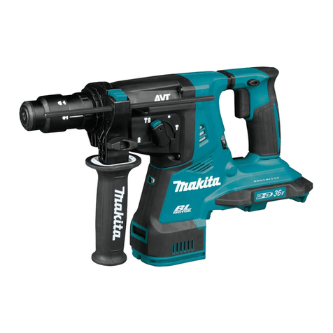
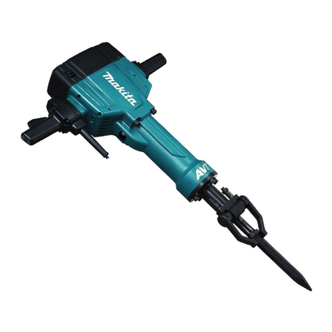
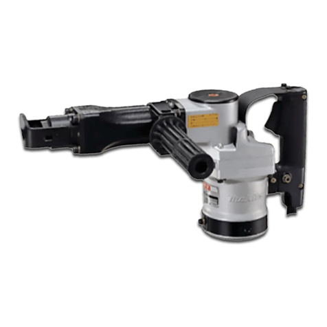
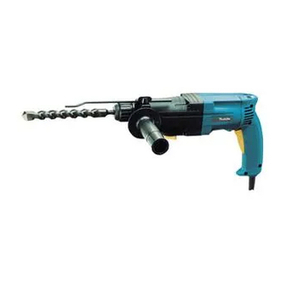
Makita HM0810 User manual

Makita

Makita HM0810 User manual

Makita M8600G User manual

Makita

Makita M8600G User manual

Makita HM0810T User manual

Makita

Makita HM0810T User manual

Makita HM001G User manual

Makita

Makita HM001G User manual
Makita M8600 User manual

Makita

Makita M8600 User manual
Makita HR2410 Quick start guide

Makita

Makita HR2410 Quick start guide

Makita HM1500 User manual

Makita

Makita HM1500 User manual

Makita HM1111C User manual

Makita

Makita HM1111C User manual

Makita HM002G User manual

Makita

Makita HM002G User manual

Makita HM002GZ03 User manual

Makita

Makita HM002GZ03 User manual

Makita HM001G User manual

Makita

Makita HM001G User manual

Makita HM001GM201 User manual

Makita

Makita HM001GM201 User manual

Makita HM1242C User manual

Makita

Makita HM1242C User manual

Makita HM1205C User manual

Makita

Makita HM1205C User manual

Makita HM0860C User manual

Makita

Makita HM0860C User manual

Makita HM002G User manual

Makita

Makita HM002G User manual

Makita HM1111C User manual

Makita

Makita HM1111C User manual

Makita HM0871C User manual

Makita

Makita HM0871C User manual
Makita HM1205C User manual

Makita

Makita HM1205C User manual

Makita HM0871C User manual

Makita

Makita HM0871C User manual

Makita GRH10 User manual

Makita

Makita GRH10 User manual
Makita GRH07 User manual

Makita

Makita GRH07 User manual

Makita HM0871C User manual

Makita

Makita HM0871C User manual

Makita HM1202C User manual

Makita

Makita HM1202C User manual

Popular Power Hammer manuals by other brands
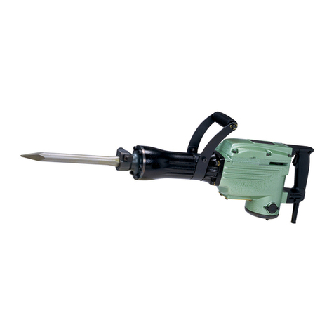
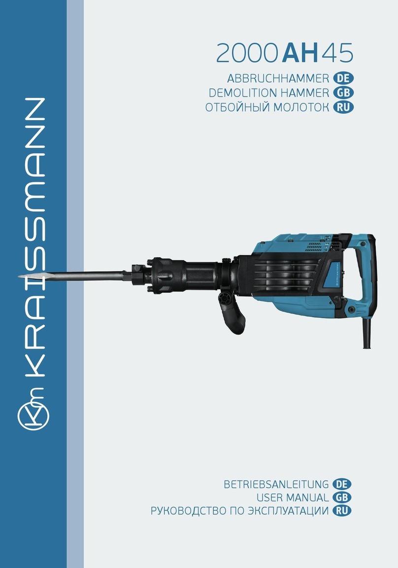
Kraissmann 2000 AH 45 user manual

Kraissmann

Kraissmann 2000 AH 45 user manual

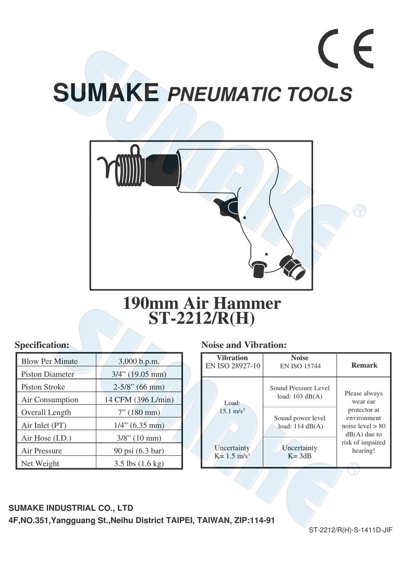
Sumake ST-2212/R manual

Sumake

Sumake ST-2212/R manual

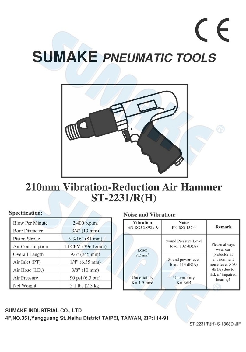
Sumake ST-2231/R quick start guide

Sumake

Sumake ST-2231/R quick start guide

Stanley STHM10 instruction manual

Stanley

Stanley STHM10 instruction manual

Villager VLN 1315 Manual instruction

Villager

Villager VLN 1315 Manual instruction

Hitachi H 65SC Instruction manual and safety instructions

Hitachi

Hitachi H 65SC Instruction manual and safety instructions

Hitachi H 65SB2 Handling instructions

Hitachi

Hitachi H 65SB2 Handling instructions
socomec MDO 6000 TS Use & maintenance

socomec

socomec MDO 6000 TS Use & maintenance
Atlas Copco PB 6S Repair instructions

Atlas Copco

Atlas Copco PB 6S Repair instructions

RODCRAFT RC5030 Operation manual

RODCRAFT

RODCRAFT RC5030 Operation manual

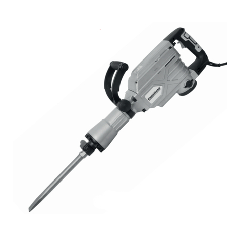
Pattfield Ergo Tools PA-1700SH Translation of the original instructions

Pattfield Ergo Tools

Pattfield Ergo Tools PA-1700SH Translation of the original instructions

Coleman Powermate 024-0075SP instruction manual

Coleman

Coleman Powermate 024-0075SP instruction manual

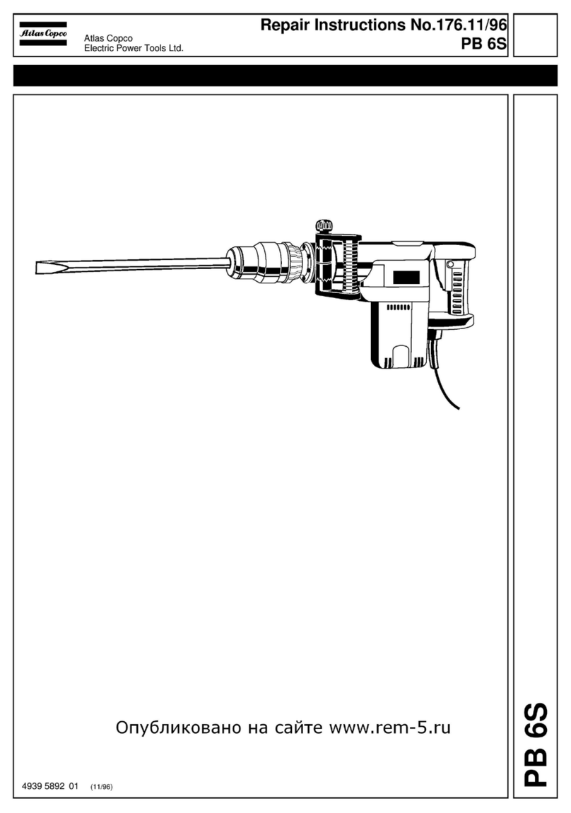
Hitachi H 45MR Technical data and service manual
Hitachi

Hitachi H 45MR Technical data and service manual

KRESS 1300 ABH Original instructions

KRESS

KRESS 1300 ABH Original instructions

Würth MH 10-SE Translation of the original operating instructions

Würth

Würth MH 10-SE Translation of the original operating instructions

DeWalt D25899 manual

DeWalt

DeWalt D25899 manual

Baileigh MH-19 Operator's manual

Baileigh

Baileigh MH-19 Operator's manual

DeWalt D25941K Original instructions

DeWalt

DeWalt D25941K Original instructions

manuals.online logo
manuals.online logoBrands
  • About & Mission
  • Contact us
  • Privacy Policy
  • Terms and Conditions

Copyright 2025 Manuals.Online. All Rights Reserved.

HM1202, HM1202C
Demolition Hammers
Continuous Rating (W)
Voltage (V) Current (A) Cycle (Hz) Input Output Max. Output(W)
100 15.0
110
120
220 7.3
230 7.0
240 6.7 550 1800
Bit-type SDS-Max
HM1202C 950-1900 (bpm)
Blows per minute HM1202 1900 (bpm)
Net Weight 9.3kg (20.5 lbs)
Cord Length 5m (16.4 ft)
Bit Grease
Bull-Point 280
The standard equipment for the tools shown may differ form country to country.
CONCEPTION AND MAIN APPLICATIONS
Specifications
Models No.
Product
TECHNICAL INFORMATION
Description
Standard equipment
Optional accessories
These demolition hammers are newly developped
as a 10 Kg hammer. (middel class between
HM1201 and HM1303 series models.) 
Considerable strong demolishing power in this class,
However, softened reaction.
Model HM1202C : equipped with electronic control system
and variable speed control dial.
Model HM1202 : without the above features.
50/60
550 1800
550 1800
500 1600
500 1600
500 1600
HM1202 HM1202C
15.0
13.0
15.0
14.0
13.0
6.8
6.5
6.3
1,450
HM1202 HM1202C HM1202 HM1202C
750
750
750
700
700
700 1500
1500
1500
1600
1600
1600
Size of shank 18mm (11/16")
Bull Point 280
Bull Point 400
Cold Chisel 25x280
Cold Chisel 25x400
Scaling Chisel 50x400
Clay Spade 105x400
Hammer Grease
112mm(4-3/8")
258mm(10-1/8")
578mm(22-3/4")
P 1 / 14
Repairing
<1> Dismounting of armature
(1) Take off the rear cover from the motor housing
by loosening 2 pcs.of tapping screw M4x18.
And then take off the carbon brushes after
taking off the brush holder cap.
(2) Take off the handle and controller cover
by loosening 2 pcs.of hex socket hd.bolt M6x40
and 4 pcs.of hex socket hd.bolt M6x30.
(3) Dismount the motor housing by loosening
4 pcs.of hex socket hd.bolt M6x40.
(4) Support the machine with the repairing jig No.1R023,
1R218 and 1R022.
Put a round stick (repairing jig No.1R234 or 1R235)
on the armature
The armature can be dismounted from the
motor housing by pushing the above round stick
with arbor press.
Screwdriver
Brush Holder Cap
Tapping screw M4x18
Hex socket hd.bolt M6x40
Hex socket hd.bolt M6x30
Controller cover
Hex socket hd.bolt M6x40
Motor housing
Base of arbor press Armature
1R022
1R023
1R218
1R234 or
1R235
Arbor press
P 2 / 14
(5) Dismounting of ball bearing 6304LLU from crank shaft.
Insert the repairing jig 1R234, 1R240 and 1R241 into the arbor on the crank shaft as per
the following illustration. And then, press with arbor press. So, Ball bearing 6304LLU can be dismounted.
Arbor press
Crank shaft
Base of arbor press
Ball bearing 6304LLU
1R234 1R240
1R241
1R032 - 1R037
1R034
(Mounting)
Make sure that the gears interlock each other, before pressing the armature
with arbor press into crank housing.
<2> Repairing on chuck section
Repairing on chuck section has to be made
with installing controller cover, because it is difficult
to keep the machine standing without it.
(Dismounting)
(1) Pull tool holder cover down in the direction
of the motor housing.
Dismount tool holder cap.
And then take off tool holder cover.
Arbor press
Tool holder cap
Tool holder cover
P 3 / 14
Cup Washer 45
Compression spring 55
<3> Repairing of piston and striker
Take off only handle, not remove controller cover.
(Dismounting)
(1) Take off change ring after dismounting of chuck section.
And then, take off ring spring 46
with pawl for retaining ring .
Dismount housing cover.
(2) Take off ring spring 25 and retaining ring WR-45
with repairing tool No.1R212.
Then, the spare parts on the chuck section can
be dismounted in the order from the bit side. 1R212
Retaining ring WR-45
Ring spring 46
Housing cover
Pawl for retaining ring
(2) Loosen 4 pcs. of hex socket head bolt M8x30.
Then barrel can be removed together with
tool holder.
Hex socket head bolt M8x30
(4 pcs.)
Barrel
P 4 / 14
(3) Hold cylinder liner 44 with hand and
strike crank housing with plastic or wooden
hammer.
Then the cylinder liner 44 can be removed from
the machine.
(Mounting)
Mount slide sleeve 49, ring 49 and
compression spring 50 on cylinder liner 44.
And then, put the cylinder liner 44 on piston.
Mount the cylinder liner to the crank housing
by pressing it with hand.
Insert striker into the cylinder liner from
the bit-installing side.
<4> Repairing of tool holder
Take off only handle, not remove controller cover.
(Dismounting)
Take off flat washer 37 after removing
ring spring 34.
Remove tool holder from barrel by pressing .
Striker
Cylinder liner 44
Slider sleeve 49
Ring 49
Compression spring 50
Crank housing
Piston
Tool holder
Ring spring 34
Barrel
Flat washer 37
Cylinder liner 44
Crank housing
P 5 / 14
(Mounting)
(1)Make sure that urethane ring 43 and O ring 38 are
mounted on tool holder in dvance. If not, mount
them on the tool holder.
Insert impact bolt into tool holder, and mount the
tool holder in barrel.
(2)Mount flat washer 37. At this time the side marked with [ UP]
has to be faced upside.
And then, fix the flat washer 37 with ring spring 34.
Impact bolt
Tool holder
Urethane ring 43
O ring 38
Barrel
Flat washer 37
The side marked with [ UP] UP
Hammer bit side
Crank housing
side
Tool holder
Ring spring 34 Barrel
Impact bolt
Steel ball 5.6
P 6 / 14
< 5> Mounting of fluoride ring
(Mounting)
(1) Fluoride ring 28, just after mounted, can not be fit
precisely along the groove on the impact bolt.
The edge come out from the groove.
(2) Insert the impact bolt on which the fluoride
ring 28 is attached, into repairing jig No.1R-214.
At this time the impact bolt has to be inserted
from the hole for [HR5001C]
And then, keep the impact bolt in the repairing jig
approx. 10 sec for correction of fluoride ring 28.
(3) Pay attention, not to damage fluoride ring 28, when
the impact bolt is inserted into tool holder.
Fluoride ring 28
of which edge has come out
from the groove.
O ring 23 O ring 23
Fluoride ring 28 corrected
with repairing jig No.1R-214
HR4000C
HR5001C
Repairing jig No.1R-214
(Taper sleeve)
Hole for
[HR5001C]
P 7 / 14
< 6> Mounting of barrel
Take off only handle, not remove controller cover.
(1) Set the of the guide ring on the of flat washer 49.
Mount the above guide ring and flat washer 49 on the 3 prongs
of slide sleeve 49.
(2) Set collared ring 24 ,rubber ring 25 and impact bolt guide
on the 3 prongs of slide sleeve 49.
(3) Set barrel (with tool holder) on the cylinder liner 44 gently paying attention
to keep rubber ring 25 and impact bolt guide on the slide sleeve's edge.
Mount compression spring 50 on crank housing by pressing it.
< Remarks>
Pay attention to the position of flat part on barrel as per the following illustration.
< 7> Mounting of controller cover
Set switch trigger in of switch lever.
ON
I
Tool holder
Barrel
Impact bold guide
Rubber ring 25
Collared
sleeve 24
Guide ring
Flat washer 49
Slide sleeve 49
Compression spring 50
Crank housing
Cylinder liner 44
Flat part on barrel
has to face in the direction
of top and bottom.
P 8 / 14
< 8> Grease
Change of grease
Change grease to fresh one when carbon brush is changed.
(1) Idle the machine for several minutes in order to warm up.
(2) Take off the handle and controller cover
by loosening 2 pcs.of hex socket hd.bolt M6x40
and 4 pcs.of hex socket hd.bolt M6x30.
And then, crank housing appears.
Hex socket hd.bolt M6x40
Hex socket hd.bolt M6x30
Handle
Crank Housing
Crank Cap
Controller cover
< Remarks >
The fresh grease to be applied has to
be limited to 30 g.
Over application can be cause of trouble.
(3) Take off crank cap.
(4) Gather the grease softened by warming up, into
the crank housing by facing the tool holder cap side
to upward.
(5) Wipe out the grease
in the crank housing
with cloth. And then, apply fresh MAKITA grease
No.00 by 30g.
P 9 / 14
The parts to be greased
The parts to be greased are marked with
(1) The parts to be greased with MAKTA grease No.00.
Impact bolt : Inner side of O ring, Out side of fluoride ring 28,
Whole part of impact bolt.
Striker : O ring 34,
Whole part of striker
Fluoride ring 28
O ring
Striker O ring 34
Piston : O ring 34,
Whole part of piston O ring 34,
Piston
Rod : Inside of the holes where piston pin
and crank shaft are installed.
Oil seal 17 : Whole of inside
P 10 / 14