Makita DFL083F User manual

DFL083F
DFL125F
DFL204F
DFL302F
DFL403F
EN Cordless Angle Screwdriver INSTRUCTION MANUAL 4
PL Bezprzewodowa wkrętarka
kątowa INSTRUKCJA OBSŁUGI 11
HU Akkumulátoros
sarok-csavarbehajtó HASZNÁLATI KÉZIKÖNYV 19
SK Akumulátorový uhlový
skrutkovač NÁVOD NA OBSLUHU 26
CS Akumulátorový úhlový
šroubovák NÁVOD K OBSLUZE 33
UK Бездротовий кутовий
шурупокрут
ІНСТРУКЦІЯ З
ЕКСПЛУАТАЦІЇ 40
RO Maşină de înşurubat
unghiulară cu acumulator MANUAL DE INSTRUCŢIUNI 48
DE Akku-Winkelschrauber BETRIEBSANLEITUNG 55

1
3
2
Fig.1
1
2
50%-70%
70%-100%
35%-50%
20%-35%
0%-20%
Fig.2
1
Fig.3
1
A
B
1
Fig.4
1
Fig.5
1
Fig.6
2

1
2
Fig.7
1
Fig.8
1
2
Fig.9
21
3
4
Fig.10
2
3
1
Fig.11
1
3
2
Fig.12
1
2
Fig.13
3

4ENGLISH
ENGLISH (Original instructions)
SPECIFICATIONS
Model: DFL083F DFL125F DFL204F DFL302F DFL403F
Fastening torque Hard joint 2 - 8 N•m 5 - 12 N•m 8 - 20 N•m
16 - 30 N•m 25 - 40 N•m
Soft joint 2 - 8 N•m 5 - 12 N•m 8 - 20 N•m
16 - 30 N•m 25 - 40 N•m
Square drive 9.5 mm
No load speed *1 150 - 700
min-1 100 - 700
min-1 100 - 440
min-1 70 - 230
min-1 50 - 220
min-1
Rated voltage D.C. 14.4 V
Overall length
(Depending on the battery)
464 - 481 mm 503 - 520 mm
Net weight 1.7 - 2.1 kg 2.0 - 2.3 kg
• Duetoourcontinuingprogramofresearchanddevelopment,thespecicationshereinaresubjecttochange
without notice.
• Specicationsmaydifferfromcountrytocountry.
• The weight may differ depending on the attachment(s), including the battery cartridge. The lightest and heavi-
est combination, according to EPTA-Procedure 01/2014, are shown in the table.
• *1 No load speed is adjustable with exclusive application.
Applicable battery cartridge and charger
Battery cartridge BL1415N / BL1415NA / BL1430 / BL1430B / BL1440 / BL1450 /
BL1460A / BL1460B
Charger DC18RC / DC18RD / DC18RE / DC18SD / DC18SE / DC18SF
• Some of the battery cartridges and chargers listed above may not be available depending on your region of
residence.
WARNING: Only use the battery cartridges and chargers listed above. Use of any other battery cartridges
andchargersmaycauseinjuryand/orre.
Intended use
The tool is intended for screw driving in wood, metal
and plastic.
Noise
The typical A-weighted noise level determined accord-
ing to EN62841:
Model DFL083F
Sound pressure level (LpA) : 70 dB(A) or less
Uncertainty (K) : 3 dB(A)
Model DFL125F
Sound pressure level (LpA) : 70 dB(A) or less
Uncertainty (K) : 3 dB(A)
Model DFL204F
Sound pressure level (LpA) : 70 dB(A) or less
Uncertainty (K) : 3 dB(A)
Model DFL302F
Sound pressure level (LpA) : 70 dB(A) or less
Uncertainty (K) : 3dB(A)
Model DFL403F
Sound pressure level (LpA) : 70 dB(A) or less
Uncertainty (K) : 3 dB(A)
The noise level under working may exceed 80 dB (A).
NOTE: The declared noise emission value(s) has
been measured in accordance with a standard test
method and may be used for comparing one tool with
another.
NOTE: The declared noise emission value(s)
may also be used in a preliminary assessment of
exposure.
WARNING: Wear ear protection.
WARNING: The noise emission during actual
use of the power tool can differ from the declared
value(s) depending on the ways in which the
tool is used especially what kind of workpiece is
processed.
WARNING: Be sure to identify safety mea-
sures to protect the operator that are based on an
estimation of exposure in the actual conditions of
use (taking account of all parts of the operating
cycle such as the times when the tool is switched
off and when it is running idle in addition to the
trigger time).

5ENGLISH
Vibration
The vibration total value (tri-axial vector sum) deter-
mined according to EN62841:
Model DFL083F
Work mode: screwdriving without impact
Vibration emission (ah) : 2.5 m/s2or less
Uncertainty (K) : 1.5 m/s2
Model DFL125F
Work mode: screwdriving without impact
Vibration emission (ah) : 2.5 m/s2or less
Uncertainty (K) : 1.5 m/s2
Model DFL204F
Work mode: screwdriving without impact
Vibration emission (ah) : 2.5 m/s2or less
Uncertainty (K) : 1.5 m/s2
Model DFL302F
Work mode: screwdriving without impact
Vibration emission (ah) : 2.5 m/s2or less
Uncertainty (K) : 1.5 m/s2
Model DFL403F
Work mode: screwdriving without impact
Vibration emission (ah) : 2.5 m/s2or less
Uncertainty (K) : 1.5 m/s2
NOTE: The declared vibration total value(s) has been
measured in accordance with a standard test method
and may be used for comparing one tool with another.
NOTE: The declared vibration total value(s) may also
be used in a preliminary assessment of exposure.
WARNING: The vibration emission during
actual use of the power tool can differ from the
declared value(s) depending on the ways in which
the tool is used especially what kind of workpiece
is processed.
WARNING: Be sure to identify safety mea-
sures to protect the operator that are based on an
estimation of exposure in the actual conditions of
use (taking account of all parts of the operating
cycle such as the times when the tool is switched
off and when it is running idle in addition to the
trigger time).
EC Declaration of Conformity
For European countries only
The EC declaration of conformity is included as Annex A
to this instruction manual.
SAFETY WARNINGS
General power tool safety warnings
WARNING: Read all safety warnings, instruc-
tions, illustrations and specications provided
with this power tool. Failure to follow all instructions
listedbelowmayresultinelectricshock,reand/or
serious injury.
Save all warnings and instruc-
tions for future reference.
The term "power tool" in the warnings refers to your
mains-operated (corded) power tool or battery-operated
(cordless) power tool.
Cordless screwdriver safety
warnings
1. Hold the power tool by insulated gripping
surfaces, when performing an operation
where the fastener may contact hidden wiring.
Fasteners contacting a "live" wire may make
exposed metal parts of the power tool "live" and
could give the operator an electric shock.
2. Always be sure you have a rm footing.
Be sure no one is below when using the tool in
high locations.
3. Hold the tool rmly.
4. Keep hands away from rotating parts.
5. Do not touch the bit or the workpiece immedi-
ately after operation; they may be extremely
hot and could burn your skin.
6. Always secure workpiece in a vise or similar
hold-down device.
SAVE THESE INSTRUCTIONS.
WARNING: DO NOT let comfort or familiarity
with product (gained from repeated use) replace
strict adherence to safety rules for the subject
product.
MISUSE or failure to follow the safety rules stated
in this instruction manual may cause serious
personal injury.
Important safety instructions for
battery cartridge
1. Before using battery cartridge, read all instruc-
tions and cautionary markings on (1) battery
charger, (2) battery, and (3) product using
battery.
2. Do not disassemble battery cartridge.
3. If operating time has become excessively
shorter, stop operating immediately. It may
result in a risk of overheating, possible burns
and even an explosion.
4. If electrolyte gets into your eyes, rinse them
out with clear water and seek medical atten-
tion right away. It may result in loss of your
eyesight.
5. Do not short the battery cartridge:
(1) Do not touch the terminals with any con-
ductive material.
(2) Avoid storing battery cartridge in a con-
tainer with other metal objects such as
nails, coins, etc.
(3) Do not expose battery cartridge to water
or rain.
A battery short can cause a large current
ow, overheating, possible burns and even a
breakdown.

6ENGLISH
6. Do not store the tool and battery cartridge in
locations where the temperature may reach or
exceed 50 °C (122 °F).
7. Do not incinerate the battery cartridge even if
it is severely damaged or is completely worn
out. The battery cartridge can explode in a re.
8. Be careful not to drop or strike battery.
9. Do not use a damaged battery.
10. The contained lithium-ion batteries are subject
to the Dangerous Goods Legislation require-
ments.
For commercial transports e.g. by third parties,
forwarding agents, special requirement on pack-
aging and labeling must be observed.
For preparation of the item being shipped, consult-
ing an expert for hazardous material is required.
Please also observe possibly more detailed
national regulations.
Tape or mask off open contacts and pack up the
battery in such a manner that it cannot move
around in the packaging.
11. When disposing the battery cartridge, remove
it from the tool and dispose of it in a safe
place. Follow your local regulations relating to
disposal of battery.
12. Use the batteries only with the products
specied by Makita. Installing the batteries to
non-compliantproductsmayresultinare,exces-
sive heat, explosion, or leak of electrolyte.
13. If the tool is not used for a long period of time,
the battery must be removed from the tool.
SAVE THESE INSTRUCTIONS.
CAUTION: Only use genuine Makita batteries.
Use of non-genuine Makita batteries, or batteries that
have been altered, may result in the battery bursting
causingres,personalinjuryanddamage.Itwill
also void the Makita warranty for the Makita tool and
charger.
Tips for maintaining maximum
battery life
1. Charge the battery cartridge before completely
discharged. Always stop tool operation and
charge the battery cartridge when you notice
less tool power.
2. Never recharge a fully charged battery car-
tridge. Overcharging shortens the battery
service life.
3. Charge the battery cartridge with room tem-
perature at 10 °C - 40 °C (50 °F - 104 °F). Let
a hot battery cartridge cool down before
charging it.
4. Charge the battery cartridge if you do not use
it for a long period (more than six months).
FUNCTIONAL DESCRIPTION
CAUTION: Always be sure that the tool is
switched off and the battery cartridge is removed
before adjusting or checking function on the tool.
Installing or removing battery cartridge
CAUTION: Always switch off the tool before
installing or removing of the battery cartridge.
CAUTION:
Hold the tool and the battery cartridge
rmly when installing or removing battery cartridge.
Failuretoholdthetoolandthebatterycartridgermlymay
cause them to slip off your hands and result in damage to
the tool and battery cartridge and a personal injury.
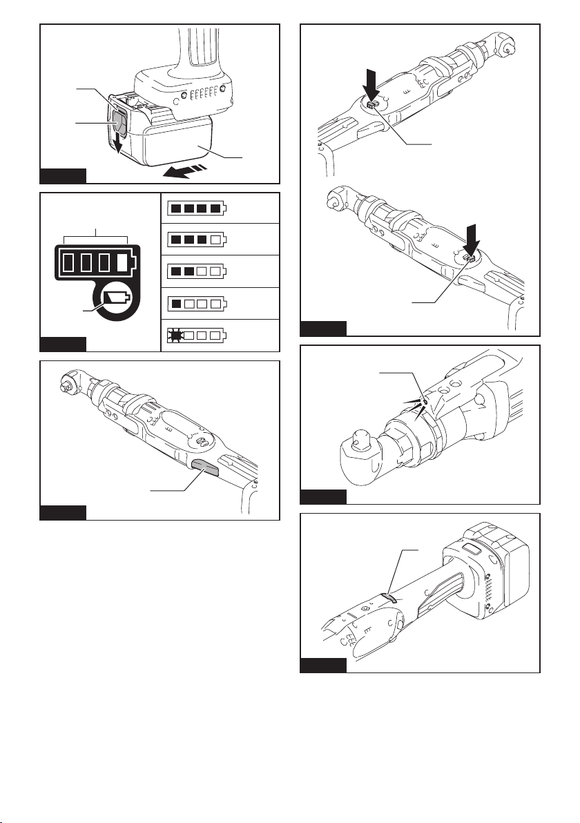
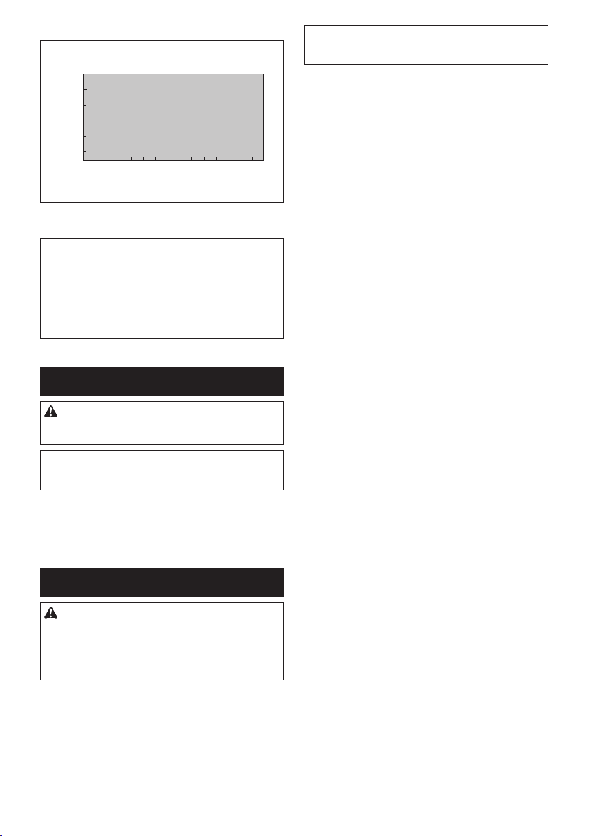
►Fig.1: 1. Red indicator 2. Button 3. Battery cartridge
To remove the battery cartridge, slide it from the tool
while sliding the button on the front of the cartridge.
To install the battery cartridge, align the tongue on the battery car-
tridge with the groove in the housing and slip it into place. Insert it all
the way until it locks in place with a little click. If you can see the red
indicator on the upper side of the button, it is not locked completely.
CAUTION:
Always install the battery cartridge fully
until the red indicator cannot be seen. If not, it may accidentally
fall out of the tool, causing injury to you or someone around you.
CAUTION: Do not install the battery cartridge
forcibly. If the cartridge does not slide in easily, it is
not being inserted correctly.
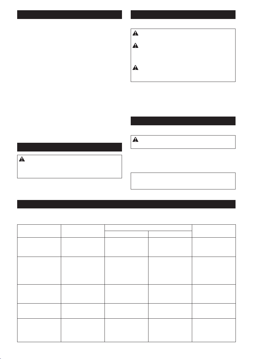
Checking the remaining battery
capacity (BL1460A)
►Fig.2: 1. Indicator lamps 2. Check button
NOTE: Depending on the conditions of use and the
ambient temperature, the indication may differ slightly
from the actual capacity.
When charging
Whenthechargingbegins,therst(farleft)indicatinglamp
beginstoicker.Then,aschargingproceeds,theotherlamps
light, one after the other, to indicate the battery capacity.
NOTE:Iftheindicatorlampdoesnotturnonoricker
when charging, the battery may be faulty. In this case,
ask your local service center.
When using
When the tool is switched on, the lamps will light to
indicate the remaining battery capacity. When the tool is
switched off, the light goes out after approx. 5 seconds.
When pushing the check button with the tool switched off, the indi-
cator lamps turn on for approx. 5 seconds to show battery capacity.
Iftheorangelampickers,thetoolstopsbecauseoflittle
remaining battery capacity (Auto-stop mechanism). Charge the
battery cartridge or use a charged battery cartridge at this time.
When the tool is used with the battery that has not been
used for a long time and is switched on, no lamps may
light up. The tool stops because of little remaining bat-
tery capacity at this time. Charge the battery properly.

7ENGLISH
Tool / battery protection system
The tool is equipped with a tool/battery protection sys-
tem. This system automatically cuts off power to the
motor to extend tool and battery life. The tool will auto-
matically stop during operation if the tool or battery is
placed under one of the following conditions:
Overload protection
When the tool/battery is operated in a manner that
causes it to draw an abnormally high current, the tool
stops automatically. In this situation, turn the tool off
and stop the application that caused the tool to become
overloaded. Then turn the tool on to restart.
Overheat protection
When the tool/battery is overheated, the tool stops
automatically. In this situation, let the tool/battery cool
before turning the tool on again.
Overdischarge protection
When the battery capacity is not enough, the tool stops
automatically. In this case, remove the battery from the
tool and charge the battery.
Switch action
WARNING: Before installing the battery car-
tridge into the tool, always check to see that the
switch trigger actuates properly and returns to
the "OFF" position when released.
►Fig.3: 1. Switch trigger
To start the tool, simply pull the switch trigger. Release
the switch trigger to stop.
Reversing switch action
►Fig.4: 1. Reversing switch lever
CAUTION: Always check the direction of
rotation before operation.
CAUTION: Use the reversing switch only after
the tool comes to a complete stop. Changing the
direction of rotation before the tool stops may dam-
age the tool.
CAUTION: When not operating the tool,
always set the reversing switch lever to the neu-
tral position.
This tool has a reversing switch to change the direction
of rotation. Depress the reversing switch lever from the
A side for clockwise rotation or from the B side for coun-
terclockwise rotation.
When the reversing switch lever is in the neutral posi-
tion, the switch trigger cannot be pulled.
Lighting up the front lamp
►Fig.5: 1. Lamp
CAUTION: Do not look in the light or see the
source of light directly.
Pull the switch trigger to light up the lamp. The lamp
keeps on lighting while the switch trigger is being pulled.
The lamp goes out approximately 10 seconds after
releasing the switch trigger.
NOTE: Use a dry cloth to wipe the dirt off the lens of
the lamp. Be careful not to scratch the lens of lamp, or
it may lower the illumination.
LED indicator / Beeper
►Fig.6: 1. LED indicator
LED indicator / Beeper on the tool shows the following functions.
Function Status of the tool Status of the LED indicator/beeper Action to be taken
LED indicator Beeper
Auto-stop with fastening
completion
The preset fasten-
ing torque has been
achieved and the tool
has stopped.
Lights up in green for
approximately one
second.
– –
Alarmagainstinsuf-
cient fastening
The preset fastening
torque has not been
achieved, because
the switch trigger has
released before complet-
ing the fastening.
Lights up in red. A long beep Retighten the screw.
Alarm for low battery
capacity
The battery power
became low and it is
time to replace the
battery cartridge.
Flickers in red slowly. A series of long beeps Replace the battery with
fully charged one.
Auto-stop with low
remaining battery
capacity
The battery power is
almost used up and the
tool stopped.
Lights up in red. A long beep Replace the battery with
fully charged one.
Check of the LED indi-
cator, light and beeper
operation
When the battery
cartridge is installed,
the tool checks for its
LED indicator, light and
beeper.
Lightsuprstingreen,
next red.
(And then the light
comes on.)
A series of very short
beeps
–

8ENGLISH
Function Status of the tool Status of the LED indicator/beeper Action to be taken
LED indicator Beeper
Anti-reset of controller The battery voltage
dropped abnormally for
some reason, and the
tool stopped.
Flickers in red and green
alternatively.
A series of short beeps Replace the battery with
fully charged one.
Overheat protection Tool's controller heated
up abnormally and the
tool stopped.
Flickers in red quickly. A series of short beeps Remove the battery car-
tridge immediately and
cool the tool down.
Detection of switch
trigger operation when
installing battery
When the battery car-
tridge is installed with
the switch trigger pulled,
the tool stops to avoid
unintentional start.
Flickers in red and green
alternatively.
A series of short beeps Release the switch
trigger.
Motor failure detection Motor failure has been
detected. At this time,
tool does not work.
Flickers in red and green
alternatively.
A series of short beeps Ask your local Makita
Service Center for repair.
Double-hitting detection When the operator
starts to re-fasten an
already-fastened screw,
the tool detect it and
stops.
Lights up in red. A long beep –
Maintenance alarm A maintenance time has
come according to your
preset number of screws
driven.
Flickers in yellow. –Reset the alarm with the
application software.
Alarm for unavailable
data communication
(with the tool in connec-
tion with PC)
Data cannot be
exchanged between the
tool and PC in spite of
the connection.
Flickers in yellow. –Restart the application
software and re-connect
the USB cable.
Indication that data com-
munication is available
(with the tool in connec-
tion with PC)
The tool is connected to
PC and data communi-
cation is available.
Flickers in green. – –
Adjusting the fastening torque
When you wish to drive machine screws, hex bolts,
etc. with the predetermined torque, adjust the fastening
torque as follows.
1. First remove the battery cartridge from the tool.
2. Loosen and remove the screw that secures the
ring and lamp cover.
►Fig.7: 1. Screw 2. Lamp cover
3. Rotate the ring in the front of the tool by hand so
that a hole can be seen below the ring.
►Fig.8: 1. Ring
4. Install the battery cartridge in place. Pull the
switch trigger and release it so that the adjust ring
rotates and the hole becomes visible. And then remove
the battery cartridge.
►Fig.9: 1. Adjust ring 2. Hole for adjust grip
5. Use an optional adjust grip to adjust the fastening
torque. Insert the pin of the adjust grip into the hole
in the front of the tool. And then, turn the adjust grip
clockwise to set a greater fastening torque, and coun-
terclockwise to set a smaller fastening torque.
6. Align the yellow line with your desired number on
the fastening torque scale.
►Fig.10: 1. Adjust grip 2. Hole for adjust grip 3. Scale
4. Yellow line
7. Insert the battery cartridge and be sure that a
fastening torque has been set up by using a fastening
torque tester.
8. Rotate the ring in front of the tool and then tighten
the screw to secure the ring and lamp cover.
NOTE: Numbers on the fastening torque scale is a
guideline to set up your desired fastening torque.
Adjusting no-load speed and
revolution angle etc.
You can adjust the no-load speed, number of turn, etc.
of the tool with your computer. Install the application
software in your computer and connect it to the tool with
an USB cable.
►Fig.11: 1. USB cable 2. USB cover 3. USB port
NOTICE: Make sure that the USB cover closed
when fastening.
NOTE: For the application software, please contact
Makita sales representative.

9ENGLISH
ASSEMBLY
CAUTION: Always be sure that the tool is
switched off and the battery cartridge is removed
before carrying out any work on the tool.
Selecting correct socket
There are different types of sockets for some models depending on
applications. Choose and install a correct socket for your application.
Installing or removing socket
►Fig.12: 1. Socket 2. Hole 3. Pin
To install the socket, push it onto the square drive of the tool
with one hand by depressing a pin on the square drive with
another hand until it locks into place. To remove the socket,
simply pull it off depressing the pin on the square drive.
CAUTION:
Before operation, make sure that
the socket is properly locked onto the square drive.
Incomplete attachment of the socket may cause injury.
Installing hook
Optional accessory
The hook is useful to hang the tool. Install the hook to
the holes on the tool body.
►Fig.13: 1. Hook 2. Hole
OPERATION
Holdthetoolrmlyandplacethesocketovertheboltornut.
Then switch the tool on. When the clutch cuts in, the motor
will stop automatically. Then release the switch trigger.
NOTE:
Hold the tool with its square drive pointed straight
at the bolt or nut, or the bolt or nut will be damaged.
Limits of fastening capacity
Use the tool within the limits of fastening capacity. If you
use the tool beyond the limits, the clutch does not work.
And the tool cannot deliver enough fastening torque.
For model DFL083F
2837
45 6
360°
300°
240°
180°
120°
60°
30°
1
3
2
N•m
1. Range of fastening capacity 2. Rotation angle
3. Torque
For model DFL125F
51
2
61
17 8 9 10
360°
300°
240°
180°
120°
60°
30°
1
3
2
N•m
1. Range of fastening capacity 2. Rotation angle
3. Torque
For model DFL204F
82
0
10 12 14 16 18
360°
300°
240°
180°
120°
60°
30°
1
3
2
N•m
1. Range of fastening capacity 2. Rotation angle
3. Torque
For model DFL302F
16 3020 25
360°
300°
240°
180°
120°
60°
30°
1
3
2
N•m
1. Range of fastening capacity 2. Rotation angle
3. Torque

10 ENGLISH
For model DFL403F
25 40
30 35
360°
300°
240°
180°
120°
60°
30°
1
3
2
N•m
1. Range of fastening capacity 2. Rotation angle
3. Torque
NOTE: The rotation angle is the angle from the point
that the bolt is tightened in 50% of desired torque to
the point that the bolt is tightened in 100% torque.
NOTE: Use of a cold battery cartridge may give
warning for battery capacity by LED indicator and
beeper and stop the tool immediately, even if it is fully
charged. In this case, the fastening capacity may be
inferiortothespecicationonthismanual.
MAINTENANCE
CAUTION:
Always be sure that the tool is
switched off and the battery cartridge is removed before
attempting to perform inspection or maintenance.
NOTICE: Never use gasoline, benzine, thinner,
alcohol or the like. Discoloration, deformation or
cracks may result.
To maintain product SAFETY and RELIABILITY,
repairs, any other maintenance or adjustment should
be performed by Makita Authorized or Factory Service
Centers, always using Makita replacement parts.
OPTIONAL ACCESSORIES
CAUTION: These accessories or attachments
are recommended for use with your Makita tool
specied in this manual. The use of any other
accessories or attachments might present a risk of
injury to persons. Only use accessory or attachment
for its stated purpose.
If you need any assistance for more details regarding
these accessories, ask your local Makita Service Center.
• Makita genuine battery and charger
• Anti kickback attachment
• Protector (Yellow, Blue, Red, Clear)
• Adjust grip
• Spindle complete
• Hook
NOTE: Some items in the list may be included in the
tool package as standard accessories. They may
differ from country to country.

11 POLSKI
POLSKI (Instrukcja oryginalna)
DANE TECHNICZNE
Model: DFL083F DFL125F DFL204F DFL302F DFL403F
Momentdokręcenia Złączkatwarda 2–8 N•m 5–12 N•m 8–20 N•m 16–30 N•m 25–40 N•m
Złączkamiękka 2–8 N•m 5–12 N•m 8–20 N•m 16–30 N•m 25–40 N•m
Zabierak kwadratowy 9,5 mm
Prędkośćbezobciążenia*1
150–700 min-1 100–700 min-1 100–440 min-1 70–230 min-1 50–220 min-1
Napięcieznamionowe Prądstały14,4V
Długośćcałkowita
(Wzależnościodbaterii)
464–481 mm 503–520 mm
Masa netto 1,7–2,1 kg 2,0–2,3 kg
• Wzwiązkuzestaleprowadzonymprzeznasząrmęprogramembadawczo-rozwojowymniniejszedanemogą
uleczmianombezwcześniejszegopowiadomienia.
• Danetechnicznemogąróżnićsięwzależnościodkraju.
• Masamożebyćróżnawzależnościodosprzętu,wtymakumulatora.Wtabeliprzedstawionajestnajlżejszai
najcięższakonguracja,zgodniezprocedurąEPTA01/2014.
• *1Prędkośćbezobciążeniamożnaregulowaćzapomocąspecjalnejaplikacji.
Kompatybilne akumulatory i ładowarki
Akumulator BL1415N / BL1415NA / BL1430 / BL1430B / BL1440 / BL1450 /
BL1460A / BL1460B
Ładowarka DC18RC / DC18RD / DC18RE / DC18SD / DC18SE / DC18SF
• Pewnezwymienionychpowyżejakumulatorówiładowarekmogąbyćniedostępnewregioniezamieszkania
użytkownika.
OSTRZEŻENIE: Należy używać wyłącznie akumulatorów i ładowarek wymienionych powyżej.
Używanieinnychakumulatorówiładowarekmożestwarzaćryzykowystąpieniaobrażeńciałalubpożaru.
Przeznaczenie
Narzędziejestprzeznaczonedowkręcaniaśrubiwkrę-
tówwdrewnie,metaluitworzywachsztucznych.
Hałas
TypowyrównoważnypoziomdźwiękuAokreślonyw
oparciuonormęEN62841:
Model DFL083F
Poziomciśnieniaakustycznego(LpA): 70 dB(A) lub mniej
Niepewność(K):3dB(A)
Model DFL125F
Poziomciśnieniaakustycznego(LpA): 70 dB(A) lub mniej
Niepewność(K):3dB(A)
Model DFL204F
Poziomciśnieniaakustycznego(LpA): 70 dB(A) lub mniej
Niepewność(K):3dB(A)
Model DFL302F
Poziomciśnieniaakustycznego(LpA): 70 dB(A) lub mniej
Niepewność(K):3dB(A)
Model DFL403F
Poziomciśnieniaakustycznego(LpA): 70 dB(A) lub mniej
Niepewność(K):3dB(A)
Poziomhałasupodczaspracymożeprzekraczać80dB(A).
WSKAZÓWKA:Deklarowanawartośćemisjihałasu
zostałazmierzonazgodniezestandardowąmetodą
testowąimożnająwykorzystaćdoporównywania
narzędzi.
WSKAZÓWKA:Deklarowanąwartośćemisjihałasu
możnatakżewykorzystaćwewstępnejocenie
narażenia.
OSTRZEŻENIE: Nosić ochronniki słuchu.
OSTRZEŻENIE: Poziom hałasu wytwa-
rzanego podczas rzeczywistego użytkowania
elektronarzędzia może się różnić od wartości
deklarowanej w zależności od sposobu użytko-
wania narzędzia, a w szczególności od rodzaju
obrabianego elementu.
OSTRZEŻENIE: W oparciu o szacowane
narażenie w rzeczywistych warunkach użytkowa-
nia należy określić środki bezpieczeństwa w celu
zapewnienia ochrony operatora (uwzględniając
wszystkie elementy cyklu działania, tj. czas, kiedy
narzędzie jest wyłączone i kiedy pracuje na biegu
jałowym, a także czas, kiedy jest włączone).

12 POLSKI
Drgania
Całkowitawartośćpoziomudrgań(sumawektoróww3
osiach)określonazgodnieznormąEN62841:
Model DFL083F
Trybpracy:wkręcaniebezudaru
Emisjadrgań(ah): 2,5 m/s2lub mniej
Niepewność(K):1,5m/s2
Model DFL125F
Trybpracy:wkręcaniebezudaru
Emisjadrgań(ah): 2,5 m/s2lub mniej
Niepewność(K):1,5m/s2
Model DFL204F
Trybpracy:wkręcaniebezudaru
Emisjadrgań(ah): 2,5 m/s2lub mniej
Niepewność(K):1,5m/s2
Model DFL302F
Trybpracy:wkręcaniebezudaru
Emisjadrgań(ah): 2,5 m/s2lub mniej
Niepewność(K):1,5m/s2
Model DFL403F
Trybpracy:wkręcaniebezudaru
Emisjadrgań(ah): 2,5 m/s2lub mniej
Niepewność(K):1,5m/s2
WSKAZÓWKA:Deklarowanawartośćpoziomu
drgańzostałazmierzonazgodniezestandardową
metodątestowąimożnająwykorzystaćdoporówny-
wanianarzędzi.
WSKAZÓWKA:Deklarowanąwartośćpoziomu
drgańmożnatakżewykorzystaćwewstępnejocenie
narażenia.
OSTRZEŻENIE: Drgania wytwarzane pod-
czas rzeczywistego użytkowania elektronarzędzia
mogą się różnić od wartości deklarowanej w
zależności od sposobu użytkowania narzędzia,
a w szczególności od rodzaju obrabianego
elementu.
OSTRZEŻENIE: W oparciu o szacowane
narażenie w rzeczywistych warunkach użytkowa-
nia należy określić środki bezpieczeństwa w celu
zapewnienia ochrony operatora (uwzględniając
wszystkie elementy cyklu działania, tj. czas, kiedy
narzędzie jest wyłączone i kiedy pracuje na biegu
jałowym, a także czas, kiedy jest włączone).
Deklaracja zgodności WE
Dotyczy tylko krajów europejskich
DeklaracjazgodnościWEjestdołączonajakozałącznik
Adoniniejszejinstrukcjiobsługi.
OSTRZEŻENIA DOTYCZĄCE
BEZPIECZEŃSTWA
Ogólne zasady bezpiecznej
eksploatacji elektronarzędzi
OSTRZEŻENIE: Należy zapoznać się z
ostrzeżeniami dotyczącymi bezpieczeństwa,
instrukcjami, ilustracjami i danymi technicz-
nymi dołączonymi do tego elektronarzędzia.
Niezastosowaniesiędopodanychponiżejinstrukcji
możeprowadzićdoporażeniaprądem,pożarui/lub
poważnychobrażeńciała.
Wszystkie ostrzeżenia i instruk-
cje należy zachować do wykorzy-
stania w przyszłości.
Pojęcie„elektronarzędzie",występującewwymienio-
nychtuostrzeżeniach,odnosisiędoelektronarzędzia
zasilanegozsiecielektrycznej(zprzewodemzasilają-
cym)lubdoelektronarzędziaakumulatorowego(bez
przewoduzasilającego).
Ostrzeżenia dotyczące
bezpieczeństwa dla wkrętarki
bezprzewodowej
1. Trzymać elektronarzędzie za izolowane
powierzchnie rękojeści podczas wykonywa-
nia prac, przy których element złączny może
dotknąć niewidocznej instalacji elektrycznej.
Zetknięcieelementówzłącznychzprzewodem
elektrycznymznajdującymsiępodnapięciemspo-
woduje,żeodsłonięteelementymetalowenarzę-
dziarównieżznajdąsiępodnapięciem,grożąc
porażeniemoperatoraprądemelektrycznym.
2. Podczas pracy należy zadbać o stabilne opar-
cie dla nóg.
W przypadku pracy na wysokości upewnić się,
że na dole nie przebywają żadne osoby.
3. Narzędzie należy trzymać mocno i pewnie.
4. Trzymać ręce z dala od części obrotowych.
5. Nie dotykać wiertła ani części obrabianej od
razu po zakończeniu danej operacji; mogą one
być bardzo gorące i spowodować oparzenie
skóry.
6. Element obrabiany należy zawsze mocować w
imadle lub podobnym uchwycie.
ZACHOWAĆ NINIEJSZE
INSTRUKCJE.
OSTRZEŻENIE: NIE WOLNO pozwolić, aby
wygoda lub rutyna (nabyta w wyniku wielokrot-
nego używania urządzenia) zastąpiły ścisłe prze-
strzeganie zasad bezpieczeństwa obsługi.
NIEWŁAŚCIWE UŻYTKOWANIE narzędzia lub
niestosowanie się do zasad bezpieczeństwa
podanych w niniejszej instrukcji obsługi może
prowadzić do poważnych obrażeń ciała.

13 POLSKI
Ważne zasady bezpieczeństwa
dotyczące akumulatora
1.
Przed użyciem akumulatora zapoznać się ze
wszystkimi instrukcjami i znakami ostrzegaw-
czymi na (1) ładowarce, (2) akumulatorze i (3)
produkcie, w którym będzie używany akumulator.
2. Akumulatora nie wolno rozbierać.
3. Jeśli czas działania uległ znacznemu skróce-
niu, należy natychmiast przerwać pracę. Może
bowiem dojść do przegrzania, ewentualnych
poparzeń, a nawet eksplozji.
4. W przypadku przedostania się elektrolitu do
oczu, przemyć je czystą wodą i niezwłocznie
uzyskać pomoc lekarską. Może on bowiem
spowodować utratę wzroku.
5. Nie doprowadzać do zwarcia akumulatora:
(1) Nie dotykać styków materiałami przewo-
dzącymi prąd.
(2) Unikać przechowywania akumulatora w
pojemniku z metalowymi przedmiotami,
takimi jak gwoździe, monety itp.
(3) Chronić akumulator przed deszczem lub
wodą.
Zwarcie prowadzi do przepływu prądu elek-
trycznego o dużym natężeniu i przegrzania
akumulatora, co w konsekwencji może grozić
poparzeniami a nawet awarią urządzenia.
6. Narzędzia i akumulatora nie wolno przecho-
wywać w miejscach, w których temperatura
osiąga bądź przekracza 50°C (122°F).
7. Akumulatorów nie wolno spalać, również tych
poważnie uszkodzonych lub całkowicie zuży-
tych. Akumulator może eksplodować w ogniu.
8.
Chronić akumulator przed upadkiem i uderzeniami.
9. Nie wolno używać uszkodzonego akumulatora.
10. Stanowiące wyposażenie akumulatory lito-
wo-jonowe podlegają przepisom dotyczącym
produktów niebezpiecznych.
Napotrzebytransportukomercyjnego,np.świad-
czonegoprzezrmytrzecieczyspedycyjne,
należyprzestrzegaćspecjalnychwymagańw
zakresie pakowania i oznaczania etykietami.
Przygotowanieproduktudowysyłkiwymagaskon-
sultowaniasięzespecjalistąds.materiałówniebez-
piecznych.Należytakżeprzestrzegaćprzepisów
krajowych,któremogąbyćbardziejszczegółowe.
Zakleićtaśmąlubzaślepićotwartestykiakumula-
toraorazzabezpieczyćgo,abyniemógłsięprze-
suwaćwopakowaniu.
11.
Jeśli zajdzie konieczność utylizacji akumulatora,
należy wyjąć go z narzędzia i przekazać w bez-
pieczne miejsce. Postępować zgodnie z przepisami
lokalnymi dotyczącymi utylizacji akumulatorów.
12. Używać akumulatorów tylko z produktami
określonymi przez rmę Makita. Zastosowanie
akumulatorówwniezgodnychproduktachmoże
spowodowaćpożar,przegrzanie,wybuchlub
wyciek elektrolitu.
13. Jeśli narzędzie nie będzie używane przez dłuż-
szy czas, należy wyjąć z niego akumulator.
ZACHOWAĆ NINIEJSZE
INSTRUKCJE.
PRZESTROGA:
Używać wyłącznie oryginalnych
akumulatorów rmy Makita.Używanienieoryginalnych
akumulatorówrminnychniżMakitalubakumulatorów,
którezostałyzmodykowane,możespowodowaćwybuch
akumulatoraipożar,obrażeniaciałaorazzniszczeniemie-
nia.Stanowitorównieżnaruszeniewarunkówgwarancji
rmyMakitadotyczącychnarzędziaiładowarki.
Wskazówki dotyczące zachowania
maksymalnej trwałości akumulatora
1.
Akumulator należy naładować zanim zostanie do końca
rozładowany. Po zauważeniu spadek mocy narzędzia
należy przerwać pracę i naładować akumulator.
2. Nie wolno ładować powtórnie w pełni nałado-
wanego akumulatora. Przeładowanie akumula-
tora skraca jego trwałość.
3.
Akumulator należy ładować w temperaturze poko-
jowej w przedziale 10–40°C (50–104°F). W przy-
padku gorącego akumulatora przed przystąpie-
niem do ładowania należy poczekać, aż ostygnie.
4. Akumulatory niklowo-wodorkowe należy nała-
dować po okresie długiego nieużytkowania
(dłuższego niż sześć miesięcy).
OPIS DZIAŁANIA
PRZESTROGA: Przed przystąpieniem do regu-
lacji lub przeglądu narzędzia upewnić się, że jest
ono wyłączone, a akumulator został wyjęty.
Wkładanie i wyjmowanie akumulatora
PRZESTROGA: Przed włożeniem lub wyjęciem
akumulatora należy zawsze wyłączyć narzędzie.
PRZESTROGA: Podczas wkładania lub wyjmo-
wania akumulatora należy mocno trzymać narzę-
dzie i akumulator.Wprzeciwnymraziemogąsięone
wyślizgnąćzrąk,powodującuszkodzenienarzędzia
lubakumulatoraiobrażeniaciała.
►Rys.1: 1.Czerwonywskaźnik2. Przycisk
3. Akumulator
Abywyjąćakumulator,przesuńprzyciskznajdującysię
wprzedniejjegoczęściiwysuńakumulator.
Abywłożyćakumulator,wyrównajwystępnaakumulato-
rzezrowkiemwobudowieiwsuńgonaswojemiejsce.
Akumulatornależywsunąćdooporu,ażsięzatrzaśniena
miejscu,cojestsygnalizowanedelikatnymkliknięciem.
Jeśliwgórnejczęściprzyciskujestwidocznyczerwony
wskaźnik,akumulatorniezostałcałkowiciezatrzaśnięty.
PRZESTROGA: Akumulator należy włożyć
do końca, tak aby czerwony wskaźnik nie był
widoczny.Wprzeciwnymraziemożeprzypadkowo
wypaśćznarzędzia,powodującobrażeniaoperatora
lubosóbpostronnych.
PRZESTROGA: Nie wkładać akumulatora na
siłę.Jeśliakumulatorniedajesięswobodniewsunąć,
oznaczato,żezostałwłożonynieprawidłowo.

14 POLSKI
Sprawdź stan naładowania
akumulatora (BL1460A)
►Rys.2: 1.Lampkiwskaźnika2. Przycisk kontrolny
WSKAZÓWKA:Zależnieodwarunkówużytkowania
itemperaturyotoczenia,wskazywanypoziommoże
nieznaczniesięróżnićodrzeczywistegostanunała-
dowania akumulatora.
Podczas ładowania
Porozpoczęciuładowaniaakumulatorapierwszakon-
trolka(ostatniaodlewej)zaczynamigać.Następnie
wmiarępostępuładowaniazapalająsięjednapo
drugiejpozostałelampkiwskazującestannaładowania
akumulatora.
WSKAZÓWKA:Jeślikontrolkaniewłączysięinie
migapodczasładowania,akumulatormożebyć
uszkodzony.Wtakimwypadkunależyzwrócićsiędo
lokalnego punktu serwisowego.
Podczas eksploatacji
Gdyurządzeniezostajewłączone,zapalająsiękontrolki
wskazującestannaładowaniaakumulatora.Gdyurzą-
dzeniezostajewyłączone,poupływieokoło5sekund
wyłączasięrównieżkontrolka.
Ponaciśnięciuprzyciskukontrolnegoprzywyłączonym
narzędziulampkiwskaźnikówwłączająsięnaok.5
sekund,abywskazaćstannaładowaniaakumulatora.
Jeślipomarańczowakontrolkamiga,narzędziezostaniezatrzy-
manezewzględunaniskistannaładowaniaakumulatora(mecha-
nizmsamoczynnegozatrzymywania).Wówczasnależynaładować
akumulatorlubzastosowaćinny,naładowanyakumulator.
Żadnakontrolkamożesięniezapalić,jeżelinarzędzie
zostaniewłączonezwłożonymakumulatorem,którynie
byłużywanyprzezdłuższyczas.Narzędziezatrzymuje
sięzewzględunazbytniskistannaładowaniaakumula-
tora.Odpowiednionaładowaćakumulator.
Układ zabezpieczenia narzędzia/
akumulatora
Narzędziejestwyposażonewukładzabezpieczenia
narzędzia/akumulatora.Układautomatycznieodcina
zasilaniesilnikawceluwydłużeniatrwałościnarzędzia
iakumulatora.Narzędziezostanieautomatycznie
zatrzymanepodczaspracywnastępującychsytuacjach
związanychznarzędziemlubakumulatorem:
Zabezpieczenie przed przeciążeniem
Wprzypadkuużytkowanianarzędzia/akumulatoraw
sposóbpowodującynadmierniewysokipobórprądu
narzędziezostanieautomatyczniezatrzymane.Wtakiej
sytuacjinależywyłączyćnarzędzieizaprzestaćwyko-
nywaniaczynnościpowodującejprzeciążenienarzę-
dzia.Następnienależywłączyćnarzędziewcelujego
ponownego uruchomienia.
Zabezpieczenie przed przegrzaniem
Wprzypadkuprzegrzanianarzędzia/akumulatora
narzędziewyłączysięautomatycznie.Wtakiejsytuacji
należyodczekać,ażnarzędzie/akumulatorostygnie
przedponownymwłączeniemnarzędzia.
Zabezpieczenie przed nadmiernym
rozładowaniem
Gdystannaładowaniaakumulatorastaniesięzbyt
niski,narzędziezostanieautomatyczniezatrzymane.
Wtakiejsytuacjinależywyjąćakumulatorznarzędziai
naładowaćgo.
Działanie przełącznika
OSTRZEŻENIE: Przed włożeniem akumu-
latora do narzędzia należy zawsze sprawdzić,
czy spust przełącznika działa prawidłowo i
czy powraca do położenia wyłączenia po jego
zwolnieniu.
►Rys.3: 1.Spustprzełącznika
Wceluuruchomienianarzędziawystarczypociągnąć
spustprzełącznika.Wceluwyłączeniawystarczyzwol-
nićspustprzełącznika.
Działanie przełącznika zmiany
kierunku obrotów
►Rys.4: 1.Dźwigniaprzełącznikazmianykierunku
obrotów
PRZESTROGA: Przed przystąpieniem do pracy
należy zawsze sprawdzić ustawiony kierunek
obrotów.
PRZESTROGA: Przełącznika zmiany kie-
runku obrotów można użyć tylko po całkowitym
zatrzymaniu narzędzia. Zmiana kierunku obro-
tówprzedzatrzymaniemsięnarzędziagrozijego
uszkodzeniem.
PRZESTROGA: Gdy narzędzie nie jest uży-
wane, należy zawsze ustawić dźwignię prze-
łącznika zmiany kierunku obrotów w położeniu
neutralnym.
Omawianenarzędziejestwyposażonewprzełącznik
umożliwiającyzmianękierunkuobrotów.Wceluuzy-
skaniaobrotówwprawąstronęnależywcisnąćdźwi-
gnięprzełącznikazmianykierunkuobrotówpostronie
A,natomiastabyuzyskaćobrotywlewąstronę,należy
wcisnąćdźwignięprzełącznikapostronieB.
Gdydźwigniaprzełącznikazmianykierunkuobrotów
znajdujesięwpołożeniuneutralnym,spustprzełącz-
nika jest zablokowany.
Włączanie lampki czołowej
►Rys.5: 1. Lampka
PRZESTROGA: Nie patrzeć na światło ani
bezpośrednio na źródło światła.
Wceluwłączenialampkinależypociągnąćzaspust
przełącznika.Lampkaświeci,dopókispustprzełącznika
jestnaciskany.Lampkawyłączasiępookoło10sod
zwolnieniaspustuprzełącznika.
WSKAZÓWKA:Abyusunąćzabrudzeniazklosza
lampki,należyużyćsuchejszmatki.Uważać,abynie
zarysowaćkloszalampki,gdyżmożetozmniejszyć
natężenieoświetlenia.

15 POLSKI
Wskaźnik LED/sygnał dźwiękowy
►Rys.6: 1.WskaźnikLED
WskaźnikLED/sygnałdźwiękowynanarzędziuwskazujenastępującefunkcje.
Funkcja Stana narzędzia Stan wskaźnika LED/sygnału dźwiękowego Wymagane działanie
Wskaźnik LED Sygnał dźwiękowy
Samoczynne zatrzyma-
niewzwiązkuzzakoń-
czeniemdokręcania
Nastawiony moment
dokręceniazostał
osiągniętyinarzędzie
zostałozatrzymane.
Świecinazielonoprzez
okołojednąsekundę.
– –
Alarmdotyczący
niewystarczającego
dokręcania
Nastawiony moment
dokręcenianiezostał
osiągnięty,ponieważ
spustprzełącznikazostał
zwolnionyprzedzakoń-
czeniemdokręcenia.
Świecinaczerwono. Długisygnałdźwiękowy Dokręcićponownie
śrubę.
Alarmdotyczący
niskiegostanunałado-
wania akumulatora
Stannaładowaniaaku-
mulatorajestjużniski,w
związkuzczymnależy
wymienićakumulator.
Miga na czerwono w
wolnym tempie.
Seriadługichsygnałów
dźwiękowych
Wymienićakumulatorna
wpełninaładowany.
Samoczynne zatrzyma-
niewzwiązkuzniskim
stanemnaładowania
akumulatora
Energia akumulatora
zostałprawiezużyta
inarzędziezostało
zatrzymane.
Świecinaczerwono. Długisygnałdźwiękowy Wymienićakumulatorna
wpełninaładowany.
Kontroladziałania
wskaźnikaLED,lampkii
sygnałudźwiękowego
Po zamontowaniu
akumulatoranarzędzie
sprawdzadziałanie
wskaźnikaLED,lampkii
sygnałudźwiękowego.
Wskaźnikświecisię
najpierw na zielono, a
następnienaczerwono.
(Potemwłączasię
lampka).
Seriabardzokrótkich
sygnałówdźwiękowych
–
Zabezpieczenie przed
resetem sterownika
Napięcieakumulatoraz
jakiegośpowoduspadło
wsposóbnietypowy
inarzędziezostało
zatrzymane.
Świecinaprzemianna
czerwono i zielono.
Seriakrótkichsygnałów
dźwiękowych
Wymienićakumulatorna
wpełninaładowany.
Zabezpieczenie przed
przegrzaniem
Kontrolernarzędzia
nagrzałsięwsposób
nietypowyinarzędzie
zostałozatrzymane.
Miga szybko na
czerwono.
Seriakrótkichsygnałów
dźwiękowych
Wyjąćnatychmiast
akumulatoriodczekać,
ażnarzędzieostygnie.
Wykryciedziałania
spustuprzełącznikaprzy
montażuakumulatora
Gdy akumulator jest
montowanyzwycią-
gniętymspustem
przełącznika,narzędzie
jest zatrzymywane, co
zapobiega niezamierzo-
nemu uruchomieniu.
Świecinaprzemianna
czerwono i zielono.
Seriakrótkichsygnałów
dźwiękowych
Zwolnićspust
przełącznika.
Wykrycie usterki silnika Wykrytousterkęsilnika.
Wtymczasienarzędzie
niebędziedziałało.
Świecinaprzemianna
czerwono i zielono.
Seriakrótkichsygnałów
dźwiękowych
Zlecićnaprawęwlokal-
nym autoryzowanym
punkcie serwisowym
Makita.
Wykryciepodwójnego
dokręcenia
Gdy operator zacznie
dokręcaćjużdokrę-
conąśrubę,narzędzie
to wykryje i zostanie
zatrzymane.
Świecinaczerwono. Długisygnałdźwiękowy –
Alarm konserwacji Na podstawie ustawionej
liczbyprzykręconych
śrubwymaganajest
konserwacja.
Miganażółto. –Skasowaćalarmprzy
użyciuoprogramowania
aplikacyjnego.
Alarmdotyczący
niedostępnościkomu-
nikacji danych (przy
narzędziupołączonymz
komputerem)
Pomimopołączenia
międzynarzędziema
komputeremniemożna
przesyłaćdanych.
Miganażółto. –Uruchomićponownie
oprogramowanie apli-
kacyjne i jeszcze raz
połączyćkabelUSB.
Sygnalizacja,że
komunikacja danych
jestdostępna(przy
narzędziupołączonymz
komputerem)
Narzędziejestpołą-
czone z komputerem i
komunikacja danych jest
dostępna.
Miga na zielono. – –

16 POLSKI
Regulacja momentu dokręcenia
Abywkręcaćśrubymaszynowe,śrubysześciokątneitp.
zokreślonymmomentemdokręcenia,należyustawić
momentdokręceniawnastępującysposób.
1. Najpierwwyjąćznarzędziaakumulator.
2. Odkręcićiwyjąćśrubęmocującąpierścieńi
osłonęlampki.
►Rys.7: 1.Wkręt2.Osłonalampki
3. Obrócićrękąpierścieńzprzodunarzędziatak,
abywidaćbyłootwórznajdującysiępodpierścieniem.
►Rys.8: 1.Pierścień
4. Włóżakumulatornamiejsce.Pociągnijspustprze-
łącznikaizwolnijgo,abypierścieńregulującysięobró-
ciłiabyotwórbyłwidoczny.Terazwyjmijakumulator.
►Rys.9: 1.Pierścieńregulacyjny2.Otwórnauchwyt
regulujący
5. Użyjopcjonalnegouchwyturegulującego,aby
wyregulowaćmomentdokręcania.Wsuńkołkiuchwytu
regulującegodootworówzprzodunarzędzia.Teraz
obróćuchwytregulującywkierunkuzgodnymzruchem
wskazówekzegara,abyustawićwiększymoment
dokręcanialubwkierunkuodwrotnymdoruchuwskazó-
wekzegara,abyuzyskaćmniejszymomentobrotowy.
6. Wyrównajżółtąlinięzżądanymnumeremnaskali
momentudokręcania.
►Rys.10: 1.Uchwytregulujący2.Otwórnauchwyt
regulujący3.Podziałka4.Żółtalinia
7. Włożyćakumulatorisprawdzićprzyużyciutestera
momentudokręcenia,czyzostałustawionywłaściwy
momentdokręcania.
8. Obrócićpierścieńzprzodunarzędzia,anastęp-
niedokręcićśrubę,abyzamocowaćpierścieńiosłonę
lampki.
WSKAZÓWKA:Numerynaskalimomentudokręca-
niastanowiąwskazówkęprzydatnąpodczasustawia-
niażądanegomomentudokręcania.
Regulacja prędkości bez obciążenia,
kąta obrotów itd.
Zapomocąkomputeramożnaregulowaćprędkośćbez
obciążenia,liczbęobrotówitd.Zainstalowaćoprogra-
mowanienakomputerzeipołączyćgoznarzędziemza
pomocąkablaUSB.
►Rys.11: 1. Kabel USB 2. Klapka USB 3. Port USB
UWAGA:Dopilnować,abyklapkaUSBbyła
zamkniętapodczasdokręcania.
WSKAZÓWKA:Abyuzyskaćoprogramowanie,
należyskontaktowaćsięzprzedstawicielemhandlo-
wymrmyMakita.
MONTAŻ
PRZESTROGA: Przed przystąpieniem do prac
konserwacyjnych przy narzędziu upewnić się,
że jest ono wyłączone, a akumulator został wyjęty.
Wybór prawidłowej końcówki
nasadowej
Dlaniektórychmodelidostępnesąróżnetypykoń-
cóweknasadowych,którywybórjestuzależnionyod
zastosowania.Należywybraćizamontowaćkońcówkę
nasadowąodpowiedniądladanegozastosowania.
Zakładanie i zdejmowanie końcówki
nasadowej
►Rys.12: 1.Końcówkanasadowa2.Otwór3.Kołek
Abyzałożyćkońcówkęnasadową,należywpychaćją
jednąrękąnazabierakkwadratowynarzędzia,adrugą
rękąwciskaćkołeknakwadratowymzabieraku,aby
wskoczyłnaswojemiejsce.Abyzdjąćkońcówkęnasa-
dową,należypoprostująwyciągnąć,wciskająckołek
na kwadratowym zabieraku.
PRZESTROGA: Przed rozpoczęciem pracy
należy się upewnić, że końcówka nasadowa jest
dobrze zablokowana na kwadratowym zabieraku.
Złezamocowaniekońcówkinasadowejmożespowo-
dowaćobrażeniaciała.
Zamontowanie zaczepu
Akcesoria opcjonalne
Zaczepjestprzydatnydozawieszanianarzędzia.
Włożyćzaczepdootworówwkorpusienarzędzia.
►Rys.13: 1. Zaczep 2.Otwór
OBSŁUGA
Trzymaćmocnonarzędzieiumieścićkońcówkę
nasadowąnaśrubielubnakrętce.Następniewłącz
narzędzie.Kiedysprzęgłosięwyłączy,silnikzatrzyma
sięautomatycznie.Następnienależyzwolnićspust
przełącznika.
WSKAZÓWKA:Trzymaćnarzędzietak,abykwa-
dratowyzabierakbyłskierowanyprostonaśrubę
lubnakrętkę,wprzeciwnymrazieśrubalubnakrętka
mogąulecuszkodzeniu.

17 POLSKI
Zakresy wydajności dokręcania
Używajnarzędziawobrębiedopuszczalnegozakresu
wydajnościdokręcania.Jeżelinarzędziebędzieuży-
wanepowyżejdopuszczalnegozakresu,sprzęgłonie
będziedziałać.Wtedynarzędzieniezapewniawystar-
czającegomomentudokręcania.
Dla modelu DFL083F
2837
45 6
360°
300°
240°
180°
120°
60°
30°
1
3
2
N•m
1.Zakresdokręcania2.Kątobrotów3. Moment
obrotowy
Dla modelu DFL125F
51
2
61
17 8 9 10
360°
300°
240°
180°
120°
60°
30°
1
3
2
N•m
1.Zakresdokręcania2.Kątobrotów3. Moment
obrotowy
Dla modelu DFL204F
82
0
10 12 14 16 18
360°
300°
240°
180°
120°
60°
30°
1
3
2
N•m
1.Zakresdokręcania2.Kątobrotów3. Moment
obrotowy
Dla modelu DFL302F
16 3020 25
360°
300°
240°
180°
120°
60°
30°
1
3
2
N•m
1.Zakresdokręcania2.Kątobrotów3. Moment obrotowy
Dla modelu DFL403F
25 40
30 35
360°
300°
240°
180°
120°
60°
30°
1
3
2
N•m
1.Zakresdokręcania2.Kątobrotów3. Moment obrotowy
WSKAZÓWKA:Kątobrotówtokątodmiejsca,w
którymśrubajestdokręconaw50%wymaganego
momentudomiejsca,wktórymśrubajestdokręcona
w 100% momentu.
WSKAZÓWKA:Użyciezimnegoakumulatoramoże
skutkowaćostrzeżeniemdotyczącymstanunałado-
waniaakumulatoraprzezwskaźnikLEDorazsygnał
dźwiękowyinatychmiastowymzatrzymaniemnarzę-
dzia,nawetjeśliakumulatorjestwpełninaładowany.
Wtakimprzypadkuwydajnośćdokręcaniamożebyć
gorszaodtej,którąpodanowinstrukcji.
KONSERWACJA
PRZESTROGA: Przed przystąpieniem do prze-
glądu narzędzia lub jego konserwacji upewnić się,
że jest ono wyłączone, a akumulator wyjęty.
UWAGA: Nie stosować benzyny, rozpuszczalni-
ków, alkoholu itp. środków. Mogą one powodo-
wać odbarwienia, odkształcenia lub pęknięcia.
W celu zachowania odpowiedniego poziomu
BEZPIECZEŃSTWAiNIEZAWODNOŚCIproduktu
wszelkienaprawyiróżnegorodzajupracekonserwacyjne
lubregulacjepowinnybyćprzeprowadzaneprzezautory-
zowanylubfabrycznypunktserwisowynarzędziMakita,
zawszezużyciemoryginalnychczęścizamiennychMakita.

18 POLSKI
AKCESORIA
OPCJONALNE
PRZESTROGA: Zaleca się stosowanie wymie-
nionych akcesoriów i przystawek razem z narzę-
dziem Makita opisanym w niniejszej instrukcji.
Stosowanieinnychakcesoriówlubprzystawek
możebyćprzyczynąobrażeńciała.Akcesorialub
przystawkinależywykorzystywaćtylkozgodniezich
przeznaczeniem.
Wraziepotrzebywszelkiejpomocyiszczegółowych
informacjinatematniniejszychakcesoriówudzielą
PaństwulokalnepunktyserwisoweMakita.
• OryginalnyakumulatoriładowarkarmyMakita
• Przystawkazabezpieczającaprzedodrzutem
• Osłona(żółta,niebieska,czerwona,
przezroczysta)
• Uchwytregulujący
• Wrzeciono kompletne
• Zaczep
WSKAZÓWKA:Niektórepozycjeznajdującesięna
liściemogąbyćdołączonedopakietunarzędziowego
jakoakcesoriastandardowe.Mogątobyćróżne
pozycje,wzależnościodkraju.

19 MAGYAR
MAGYAR (Eredeti utasítások)
RÉSZLETES LEÍRÁS
Típus: DFL083F DFL125F DFL204F DFL302F DFL403F
Meghúzási nyomaték Merevösszekötő 2–8 N•m 5–12 N•m 8–20 N•m 16–30 N•m 25–40 N•m
Lágyösszekötő 2–8 N•m 5–12 N•m 8–20 N•m 16–30 N•m 25–40 N•m
Négyszögletescsavarbehajtó 9,5 mm
Üresjárati fordulatszám *1
150–700 min-1 100–700 min-1 100–440 min-1 70–230 min-1 50–220 min-1
Névleges feszültség 14,4 V, egyenáram
Teljes hossz
(Azakkumulátortólfüggően)
464 – 481 mm 503 – 520 mm
Nettótömeg 1,7–2,1 kg 2,0–2,3 kg
•
Folyamatoskutató-ésfejlesztőprogramunkeredményekéntazittfelsorolttulajdonságokgyelmeztetésnélkülmegváltozhatnak.
• Atulajdonságokországrólországrakülönbözhetnek.
• Asúlyafelszerelttartozékoktólfüggőenváltozhat,azakkumulátortisbeleértve.AzEPTA01/2014eljárás
szerintmeghatározottlegnehezebb,illetvelegkönnyebbkombinációatáblázatbanlátható.
• *1Azüresjáratifordulatszámkizárólagosszerszámmalállítható.
Alkalmazható akkumulátorok és töltők
Akkumulátor BL1415N / BL1415NA / BL1430 / BL1430B / BL1440 / BL1450 /
BL1460A / BL1460B
Töltő DC18RC / DC18RD / DC18RE / DC18SD / DC18SE / DC18SF
• Lakóhelyétőlfüggőenelőfordulhat,hogyafentfelsoroltakkumulátorokéstöltőknemérhetőkel.
FIGYELMEZTETÉS: Csak a fentiekben felsorolt akkumulátorokat és töltőket használja. Bármilyen más
akkumulátorvagytöltőhasználatasérüléseketés/vagytüzetokozhat.
Rendeltetés
Aszerszámcsavarbehajtásrahasználható,fába,
fémekbeésműanyagokba.
Zaj
A tipikus A-súlyozású zajszint, a EN62841 szerint
meghatározva:
DFL083F típus
Hangnyomásszint (LpA): 70 dB(A) vagy kisebb
Bizonytalanság (K): 3 dB(A)
DFL125F típus
Hangnyomásszint (LpA): 70 dB(A) vagy kisebb
Bizonytalanság (K): 3 dB(A)
DFL204F típus
Hangnyomásszint (LpA): 70 dB(A) vagy kisebb
Bizonytalanság (K): 3dB(A)
DFL302F típus
Hangnyomásszint (LpA): 70 dB(A) vagy kisebb
Bizonytalanság (K): 3dB(A)
DFL403F típus
Hangnyomásszint (LpA): 70 dB(A) vagy kisebb
Bizonytalanság (K): 3 dB(A)
A zajszint a munkavégzés során meghaladhatja a 80 dB (A) értéket.
MEGJEGYZÉS: A zajkibocsátás értéke a szabványos
vizsgálatieljárásnakmegfelelőenlettmérve,éssegít-
ségével az elektromos kéziszerszámok összehason-
líthatókegymással.
MEGJEGYZÉS:Azajkibocsátásértékéneksegítsé-
gévelelőzetesenmegbecsülhetőarezgésnekvaló
kitettség mértéke.
FIGYELMEZTETÉS: Viseljen fülvédőt!
FIGYELMEZTETÉS: A szerszám zajkibocsá-
tása egy adott alkalmazásnál eltérhet a megadott
értéktől a használat módjától, különösen a feldol-
gozott munkadarab fajtájától függően.
FIGYELMEZTETÉS: Határozza meg a kez-
elő védelmét szolgáló munkavédelmi lépéseket,
melyek az adott munkafeltételek melletti vibrációs
hatás becsült mértékén alapulnak (gyelembe
véve a munkaciklus elemeit, mint például a gép
leállításának és üresjáratának mennyiségét az
elindítások száma mellett).
Vibráció
Avibrációteljesértéke(háromtengelyűvektorösszeg)
az EN62841 szerint meghatározva:
DFL083F típus
Üzemmód:behajtásütésnélkül
Rezgéskibocsátás (ah): 2,5 m/s2vagy kisebb
Bizonytalanság (K): 1,5 m/s2

20 MAGYAR
DFL125F típus
Üzemmód:behajtásütésnélkül
Rezgéskibocsátás (ah): 2,5 m/s2vagy kisebb
Bizonytalanság (K): 1,5 m/s2
DFL204F típus
Üzemmód:behajtásütésnélkül
Rezgéskibocsátás (ah): 2,5 m/s2vagy kisebb
Bizonytalanság (K): 1,5 m/s2
DFL302F típus
Üzemmód:behajtásütésnélkül
Rezgéskibocsátás (ah): 2,5 m/s2vagy kisebb
Bizonytalanság (K): 1,5 m/s2
DFL403F típus
Üzemmód:behajtásütésnélkül
Rezgéskibocsátás (ah): 2,5 m/s2vagy kisebb
Bizonytalanság (K): 1,5 m/s2
MEGJEGYZÉS:
A rezgés teljes értéke a szabványos vizs-
gálatieljárásnakmegfelelőenlettmérve,éssegítségévelaz
elektromoskéziszerszámokösszehasonlíthatókegymással.
MEGJEGYZÉS:Arezgésteljesértékéneksegítsé-
gévelelőzetesenmegbecsülhetőarezgésnekvaló
kitettség mértéke.
FIGYELMEZTETÉS: A szerszám rezgéskibo-
csátása egy adott alkalmazásnál eltérhet a meg-
adott értéktől a használat módjától, különösen a
feldolgozott munkadarab fajtájától függően.
FIGYELMEZTETÉS:
Határozza meg a kezelő
védelmét szolgáló munkavédelmi lépéseket, melyek az
adott munkafeltételek melletti vibrációs hatás becsült
mértékén alapulnak (gyelembe véve a munkaciklus
elemeit, mint például a gép leállításának és üresjáratá-
nak mennyiségét az elindítások száma mellett).
EK Megfelelőségi nyilatkozat
Csak európai országokra vonatkozóan
AzEK-megfelelőséginyilatkozatazútmutató„A”mel-
lékletébentalálható.
BIZTONSÁGI
FIGYELMEZTETÉS
A szerszámgépekre vonatkozó
általános biztonsági gyelmeztetések
FIGYELMEZTETÉS:
Olvassa el a szerszám-
géphez mellékelt összes biztonsági gyelmeztetést,
utasítást, illusztrációt és a műszaki adatokat. A követke-
zőkbenleírtutasításokgyelmenkívülhagyásaelektromos
áramütést, tüzet és/vagy súlyos sérülést eredményezhet.
Őrizzen meg minden gyelmez-
tetést és utasítást a későbbi tájé-
kozódás érdekében.
Agyelmeztetésekbenszereplő"szerszámgép"kifejezés
azÖnhálózatról(vezetékes)vagyakkumulátorról(veze-
téknélküli)működtetettszerszámgépérevonatkozik.
Az akkumulátoros csavarbehajtóra
vonatkozó biztonsági
gyelmeztetések
1. Tartsa az elektromos szerszámot a szigetelt
markolófelületeinél fogva, amikor olyan műve-
letet végez, melynek során fennáll a veszélye,
hogy a rögzítő rejtett vezetékekbe ütközhet. A
rögzítőkáramalattlévővezetékekkelvalóérint-
kezésekor a szerszám fém alkatrészei is áram alá
kerülnek,ésmegrázhatjákakezelőt.
2. Mindig stabil helyzetben dolgozzon.
A szerszám magasban történő használatkor
győződjön meg arról, hogy nem tartózkodik-e
valaki odalent.
3. Tartsa stabilan a szerszámot.
4. Ne nyúljon a forgó részekhez.
5. Ne érjen a szerszámhoz vagy a munkadarab-
hoz közvetlenül a munkavégzést követően;
azok rendkívül forrók lehetnek és megégethe-
tik a bőrét.
6. A munkadarabokat mindig rögzítse satuban,
vagy más hasonló befogó eszközzel.
ŐRIZZE MEG EZEKET AZ
UTASÍTÁSOKAT.
FIGYELMEZTETÉS: NE HAGYJA, hogy (a
termék többszöri használatából eredő) kényelem
és megszokás váltsa fel a termék biztonsági elő-
írásainak szigorú betartását.
A HELYTELEN HASZNÁLAT és a használati útmu-
tatóban szereplő biztonsági előírások megsze-
gése súlyos személyi sérülésekhez vezethet.
Fontos biztonsági utasítások az
akkumulátorra vonatkozóan
1. Az akkumulátor használata előtt tanulmá-
nyozza át az akkumulátortöltőn (1), az akkumu-
látoron (2) és az akkumulátorral működtetett
terméken (3) olvasható összes utasítást és
gyelmeztető jelzést.
2. Ne szerelje szét az akkumulátort.
3. Ha a működési idő nagyon lerövidült, azonnal
hagyja abba a használatot. Ez a túlmelegedés,
esetleges égések és akár robbanás veszélyé-
vel is járhat.
4. Ha elektrolit kerül a szemébe, mossa ki azt
tiszta vízzel és azonnal kérjen orvosi segítsé-
get. Ez a látásának elvesztését okozhatja.
5. Ne zárja rövidre az akkumulátort:
(1) Ne érjen az érintkezőkhöz elektromosan
vezető anyagokkal.
(2) Ne tárolja az akkumulátort más fémtár-
gyakkal, mint pl. szegekkel, érmékkel,
stb. egy helyen.
(3) Ne tegye ki az akkumulátort víznek vagy
esőnek.
Az akkumulátor rövidzárlata nagy áramerőssé-
get, túlmelegedést, égéseket, sőt akár meghi-
básodást is okozhat.
Other manuals for DFL083F
9
This manual suits for next models
14
Table of contents
Languages:
Other Makita Power Screwdriver manuals

Makita
Makita 6807 User manual

Makita
Makita 6842 User manual

Makita
Makita DFR450ZX User manual

Makita
Makita DFR440X User manual

Makita
Makita 6801B User manual

Makita
Makita 68OODBV User manual

Makita
Makita BFL060F User manual

Makita
Makita BFS451ZJ User manual

Makita
Makita DA001G User manual

Makita
Makita 6823TP User manual