Makita FS2700 Operating instructions

Specification
Standard equipment
FS2700, FS2701
Screwdriver
Dimensions: mm (")
Width (W)
Height (H)
*for countries where noise suppressing device
is required to conform to regulations
Length (L) 301 (11-7/8) 283 (11-1/8)
FS2700 FS2701
70 (2-3/4)
207 (8-1/8)*
192 (7-9/16)
L
H
W
Specification
Net weight*: kg (lbs)
*Weight according to EPTA-Procedure 01/2003
1.8 (4.0)
Model FS2701
Power supply cord: m (ft)
Europe: 4.0 (13.1), Australia,
Brazil: 2.0 (6.6),
Other countries: 2.5 (8.2)
Europe: 4.0 (13.1)
Other countries: 2.5 (8.2)
FS2700
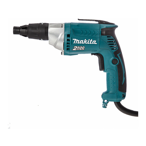
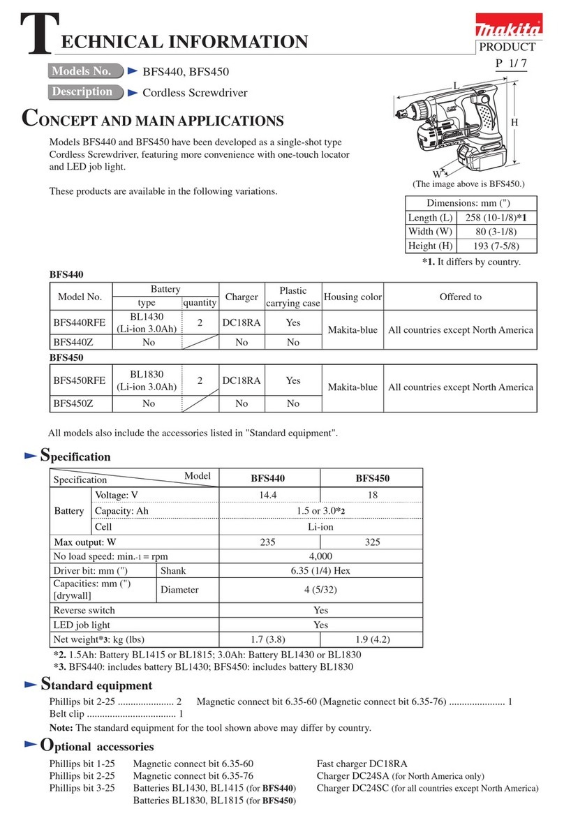
Models FS2700 and FS2701 are screwdrivers
well balanced for easy handling and maneuverability,
featuring the following main benefits;
Best possible tool body for screwdriving
More durable belt clip
6 stage torque adjustment
LED job light
FS2700 and FS2701 feature different bit change systems;
FS2700: Conventional system using leaf spring
FS2701: Bit sleeve
The both models are also available with plastic carrying case
as Models FS2700K and FS2701K.
Phillips insert bit 2-45 ....... 1 (only for countries and areas that use N-type spindle)
Plastic carrying case .......... 1 (for FS2700K and FS2701K only)
Continuous Rating (W)
Voltage (V) Cycle (Hz) Input Output Max. Output (W)
110
120
220
230
240
5.5
6.0
2.7
2.6
2.5
50/60
50/60
50/60
50/60
50/60
570
---
570
570
570
260
360
260
260
260
500
500
500
500
500
Current (A)
Note: The standard equipment for the tool shown above may vary by country.
6 (1/4)
6 (1/4)
Drywall screw
Self drilling screw
6 (1/4)Hex screw
0 - 2,500No load speed: min.-1 = rpm
Driving shank: mm (")
Capacity: mm (")
Reverse switch
Protection against electric shock
6.35 (1/4) Hex
Yes
Variable speed control by trigger Yes
Silent clutch No
LED job light Yes
Double insulation
1.7 (3.8)
Torque adjustment 6 stage setting
Bit change system Bit sleeve
Conventional system
using leaf spring
FS2700 FS2701
Models No.
Description
PRODUCT
TECHNICAL INFORMATION
CONCEPT AND MAIN APPLICATIONS
P 1/ 7
Optional accessories
FS2700 and FS2701
Phillips insert bits 2-45, 2-65, 2-110, 2-150, 2-250, 3-45, 3-65, 3-110 Socket bits 7-55, 8-55, 10-55, 10-70, 13-55, 14-55, 3/8"-55
Magnetic socket bits 1/4"-65, 5/16"-65, 3/8"-65, 7/16"-65, 10-65, 5/16"-55, 3/8"-55
FS2700 only
Front caps 12, 15.5, 1/4", 5/16", 3/8", 7/16"

[2] LUBRICATION
[3] DIFFERENCE BETWEEN FS2700 AND FS2701
[1] REPAIRING TOOL
Repair
DescriptionCode No. Use for
Gear extractor (Large)1R045 Removing Clutch cam
Bearing extractor1R269 Removing Ball bearings
Screwdriver magnetizer1R288 Removing Steel balls
1R291 Removing Sleeve
Center attachment for 1R0451R346 Using with 1R045
Retaining ring S and R pliers
Apply Makita grease FA No.2 to the following portions to protect parts and product from unusual abrasion.
Gear teeth of Spur gear (Place A: 3g) Cam portion (Place B: 1g) Contact portions (Designated by arrows: a little)
P 2/ 7
CAUTION: Repair the machine in accordance with “Instruction manual” or “Safety instructions”.
FS2700
Fig. 1
Fig. 2
FS2701
FS2700 FS2701
A: 3g
B: 2g A: 3g
B: 2g
Adjust sleeve
Front cap 12
Clutch cover A
complete
Clutch cover B
complete
Steel ball 3.5
(1pc. only)
Steel ball 3.5
(2pcs.)
Spindle 270D2
Spindle 270D
O ring 20
Ring spring 22
Leaf spring
Compression
spring 13
Ring spring 11
Flat washer 12
Sleeve

[4] DISASSEMBLY/ ASSEMBLY
[4]-1. Clutch portion
Repair
P 3/ 7
Fig. 3
1) Remove three 4x30 Tapping screws. (Fig. 3)
While holding Gear housing cover complete not to separate from Motor housing, remove Gear housing TC from Gear
housing cover complete.
2) Tap Gear housing TC using plastic hammer from Gear housing cover complete matching side. (Fig. 4) Gear complete
17-39 can be removed from Gear housing TC.
3) Turn Clutch cover A complete clockwise to remove it from Gear housing TC. (Fig. 5)
4) Turn Ring 36 complete counterclockwise to remove it from Gear housing TC. (Fig. 5)
The following parts can be removed.
Leaf spring Steel ball 3.5 Spindle 270D Compression spring 6 O ring 35 Flat washer 36 Ring spring 36
Steel ball 4 Compression spring 4
Note: Steel ball 4 is easy to drop off. Be careful not to lose it.
5) Pick out two Pins 4. (Fig. 5) An assembled part illustrated in Fig. 6 can be removed.
6) Set the assembled part as illustrated in Fig. 7 using 1R045 with 1R346.
7) While keep setting the jaws of 1R045 to Clutch cam so as not to remove, turn the handle of 1R045 to pull down Clutch
cam. Then take out one of Steel ball 5.6 from insertion hole formed by the long groove of Spur gear 35 complete and
the groove of Clutch cam. Use Slotted driver magnetized by 1R288. (Fig. 8)
8) Turn back the handle of 1R045 and reset 1R045 to Clutch cam.
Then take out the remaining Steel balls 5.6 (2pcs.) from
the insertion hole.(Fig. 9)
Note: When it is difficult to remove the third Steel ball due to
the misfit between the long groove of Spur gear 35 complete
and the groove of Clutch cam, turn the gear teeth of
Spur gear 35 complete to align their grooves.
9) Pull Spur gear 35 complete out of Sleeve, and the remaining
components can be removed as illustrated in Fig. 10.
Note: Sixteen Steel balls 3.5 are easy to drop off. Be careful not to
lose them.
DISASSEMBLING (FS2700)
Fig. 4 Fig. 5
Gear housing TC
Gear housing cover complete
Motor
housing
4x30 Tapping
screw (3pcs.)
Gear
housing TC
Gear complete 17-39 Clutch cover
A complete
Adjust sleeve
Front
cap 12
Leaf springSpindle 270D
Steel ball 3.5
Steel ball 4
O ring 35
Pin 4 (2pcs.) Ring 36
complete
Flat
washer 36
Compression
spring 6
Compression spring 4
Fig. 6 Fig. 7
Fig. 9Fig. 8
1R346
1R045
Urethane
washer 8
Thrust needle cage 821
Washer 821 (2pcs.) Spur gear 35 complete
Sleeve
Sleeve
the groove width
of Clutch cam
Screwdriver
(magnetized by 1R288)
Steel ball 5.6
(3pcs.)
Steel ball 3.2
(16pcs.)
Spur gear 35
complete
Washer 1730
(2pcs.)
Thrust needle cage Flat washer 14 Clutch cam
Compression
spring 13.6
the groove width of
Spur gear 35 complete
Gear teeth
of Spur gear
35 complete
Clutch cam Clutch cam One of Steel ball 5.6
(3pcs. in total)

[4] DISASSEMBLY/ ASSEMBLY
[4]-1. Clutch portion (cont.)
Repair
P 4/ 7
Fig. 10
1) Remove three 4x30 Tapping screws. (Fig. 3)
While holding Gear housing cover complete not to separate from Motor housing, remove Gear housing TC from
Gear housing cover complete.
2) While holding Flat washer 12 and Compression spring 13 so as not to pop out, remove Ring spring 11 from Spindle
by enlarging the gap and lifting up the ring portion of Ring spring 11 from the groove of Spindle. (Fig. 10)
Flat washer 12, Compression spring 13, Sleeve 12 and two Steel balls 3.5 can be removed.
3) Tap Gear housing TC using plastic hammer from Gear housing cover complete matching side. (Fig. 4) Gear complete
17-39 can be removed from Gear housing TC.
4) Turn Clutch cover B complete clockwise to remove it from Gear housing TC. (Fig. 11)
Spindle 270D2, Compression spring 6, O ring 35 and Flat washer 36 can be removed.
5) Turn Ring 36 complete counterclockwise to remove it from Gear housing TC. (FIg. 11)
Compression spring 4 and Steel ball 4 can be removed.
Note: Steel ball 4 is easy to drop off. Be careful not to lose it.
6) Pick out two Pins 4. (Fig. 11) An assembled part illustrated in Fig. 6 can be removed.
7) Set the assembled part as illustrated in Fig. 7 using 1R045 with 1R346.
8) While keep setting the jaws of 1R045 to Clutch cam so as not to remove, turn the handle of 1R045 to pull down
Clutch cam. Then take out one of Steel ball 5.6 from insertion hole formed by the long groove of Spur gear 35
complete and the groove of Clutch cam. Use Slotted driver magnetized by 1R288. (Fig. 7)
9) Turn back the handle of 1R045 and reset 1R045 to Clutch cam. Then take out the remaining Steel balls 5.6 (2pcs.)
from the insertion hole.(Fig. 8)
Note: When it is difficult to remove the third Steel ball due to the misfit between the long groove of Spur gear 35
complete and the groove of Clutch cam, turn the gear teeth of Spur gear 35 complete to align their grooves.
10) Pull Spur gear 35 complete out of Sleeve, and the remaining components can be removed as illustrated in Fig. 9.
Note: Sixteen Steel balls 3.5 are easy to drop off. Be careful not to lose them.
DISASSEMBLING (FS2701)
ASSEMBLING
Fig. 12 Fig. 13
Fig. 11
1R291
Gap of
Ring spring 11
Take the disassembling step in reverse.
Note: After setting Flat washer 8 for Gear complete 17-39 in place as illustrated in Fig. 12, assemble them to Gear
housing TC.
Assemble Urethane washer 8, two Washers 821 and Thrust needle cage 821 to Spur gear 35 complete properly
as illustrated in Fig. 6.
When assembling Ring 36 complete for FS2701 to Gear housing TC, hold Steel ball 4 on Gear housing TC using
thin plate to prevent Steel ball 4 from rolling along the turns of Ring spring 36 complete. (Fig. 13)
Ring portion of
Ring spring 11
Flat washer 12 and Compression
spring 13 under Ring spring 11
Sleeve
Pin 4
(2pcs.)
Flat
washer 36
Compression
spring 6
Compression
spring 4
O ring 35 Clutch cover
B complete
Spindle 270D2
Steel ball 3.5 (2pcs.)
Steel ball 4
Gear
housing
TC
Ring 36
complete
Gear complete 17-39
Flat washer 8 thin plate
Steel ball 4
on Gear
housing TC
Ring 36 complete
for FS2701
Ball bearing
606ZZ
[4] DISASSEMBLY/ ASSEMBLY
[4]-3. Replacing Armature
Repair
P5/ 7
Fig. 15Fig. 14
Fig. 17
Fig. 16
1) Loosen three 4x25 Tapping screws and remove Handle cover complete and Carbon brushes. (Fig. 14)
2) Loosen three 4x30 Tapping screws and remove the assembled parts of Gear housing, Gear housing cover and Armature
from Motor housing. (Fig. 15)
3) Remove Armature ass’y with Labyrinth rubber ring from Gear housing cover.
Armature ass’y can be disassembled as illustrated in Fig. 16. Use 1R269.
4) Take the disassembling step in reverse.
Note: Be sure to face the depressed portion of Ring 7 to Armature shaft gear end. (Fig. 17) Markings of “>PC<” “7”
are shown on the depressed portion.
4x25 Tapping
screw (3pcs.)
4x30 Tapping
screw (3pcs.)
Gear housing
cover complete
Gear housing
complete
Handle cover
complete
Motor
housing
Ring 7 (viewed
from flat side)
Ring 7 (viewed from depressed side)
Insulation
washer
Ball bearing 608VV
Ball bearing
607ZZ
Armature ass’y
Armature ass’y
Fan 52 Labyrinth
rubber ring
>PC< 7
(marking)
Armature gear
shaft end
(marking)
Fan 52Ball bearing 608VV

P 6/ 7
Fig. D-1
Circuit diagram
Color index of lead wires' sheath
Black
White
Red
Blue
Purple
Transparent
Earth terminal
for Noise
suppressor
Areas where suppression of
radio interference is required
Areas where suppression of
radio interference is required
Light
circuit
Light
circuit
Field
Brush
holder
Choke
coil
Switch
Brush
holder
Field
Brush
holder
Brush
holder
Brown
lead wire
is used
for some
countries.
Blue lead wire is used
for some countries.
Blue lead wire
is used for some
countries.
(To connect with Field laminations)
Noise
suppressor
Connector
2-SD
Power
supply cord
Power supply cord
Brown
lead wire
is used
for some
countries.

P 7/ 7
Wiring diagram
Fig. D-2
Light circuit
Strain relief*
Insert Lead wires of Light circuit into grooves of
Motor housing before clamping Power supply cord
with Strain relief* and two 4x18 Tapping screws.
Put the Lead wire’s slack of
Earth terminal in this space.
(Earth terminal is not used
for areas where suppression
of radio interference is not
required.)
Fix Lead wire of Earth terminal with Lead wire holders.
(Earth terminal is not used for areas where suppression of radio interference is not required.)
Fix Lead wires which are passed
right and left around here, with
Lead wire holders designated by a circle.
Put Noise suppressor here.
(Noise suppressor is not
used for areas where
suppression of radio
interference is not required.)
Brush holderBrush holder
Fix Lead wire with
Lead wire holders.
Fix Lead wire with
Lead wire holders.
* Note: Some specifications do not
have Strain relief.
Other manuals for FS2700
11
This manual suits for next models
1
Table of contents
Other Makita Power Screwdriver manuals

Makita
Makita 6796D User manual

Makita
Makita BFR540 User manual

Makita
Makita BFT020F User manual

Makita
Makita FS4000 User manual

Makita
Makita DDA450RTE User manual

Makita
Makita DFR540 User manual

Makita
Makita DFS250 User manual

Makita
Makita DFL020F User manual

Makita
Makita DFR452 User manual

Makita
Makita DA332DZJ User manual

Makita
Makita 6824 Quick start guide

Makita
Makita 6802BV User manual

Makita
Makita BDF441 Manual

Makita
Makita 6823 User manual

Makita
Makita BFL201R User manual

Makita
Makita 6723DW User manual

Makita
Makita 6802BV User manual

Makita
Makita DFT082R User manual

Makita
Makita FS4000 User manual

Makita
Makita DFS441 User manual