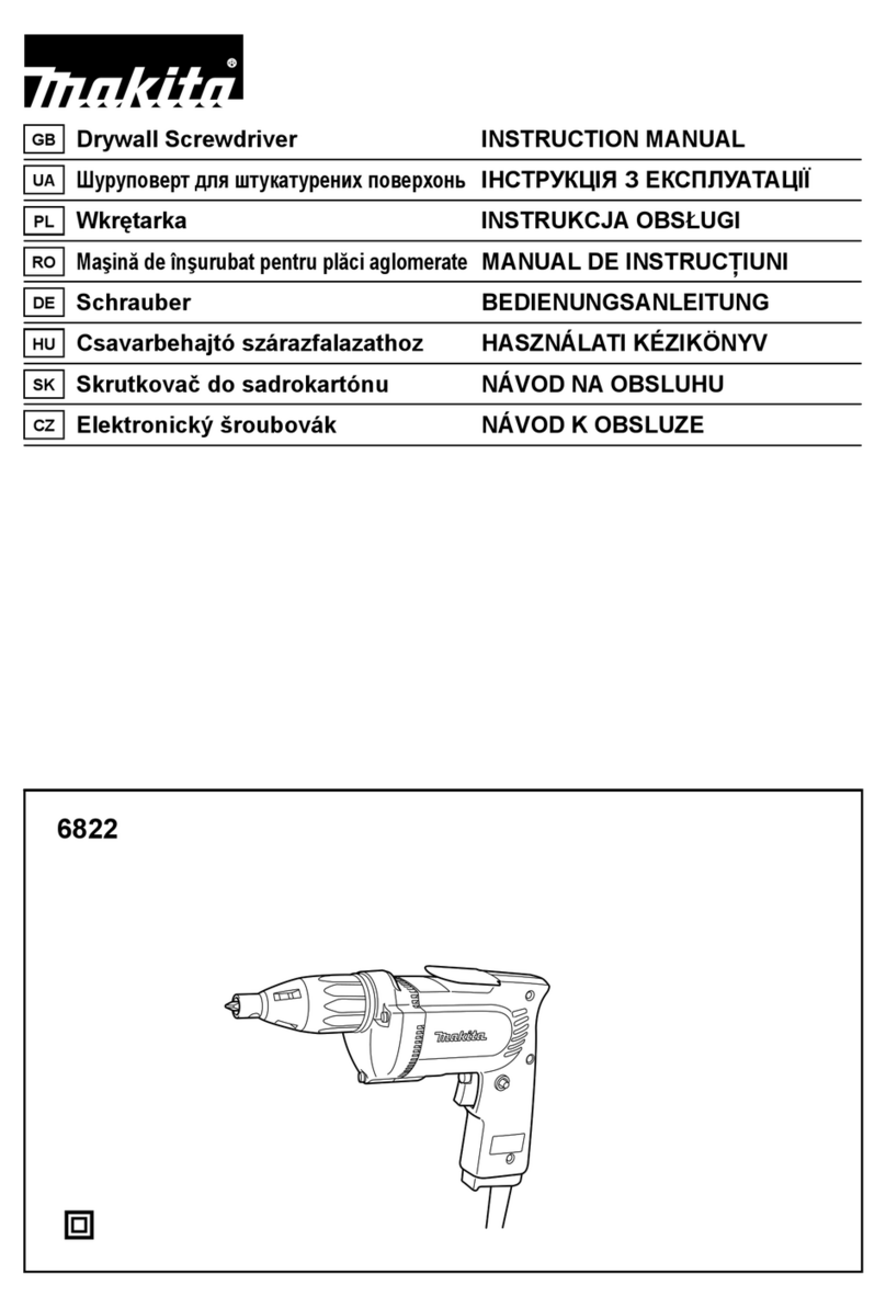
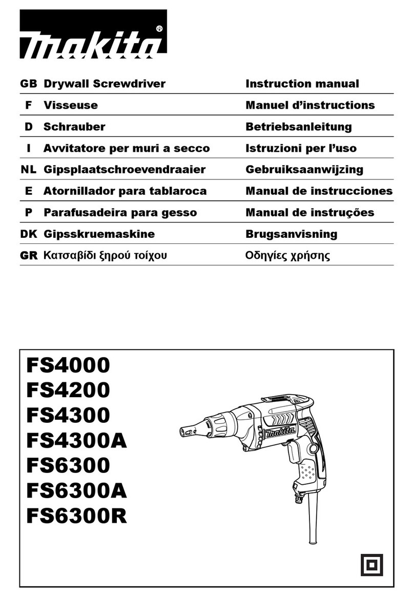
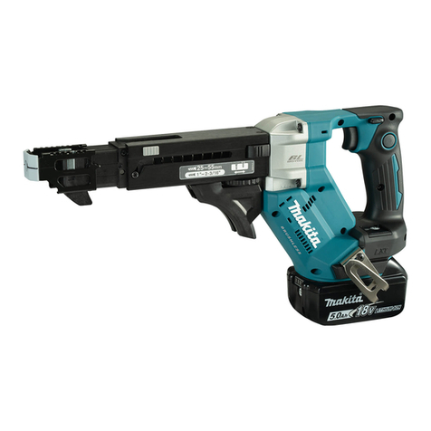
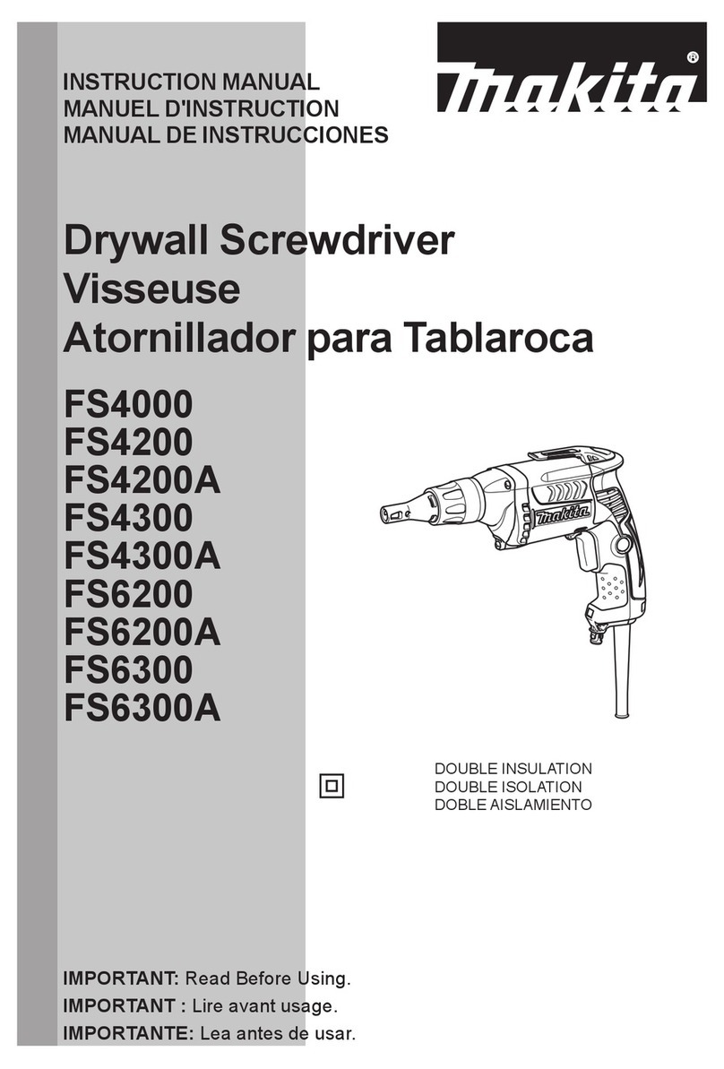
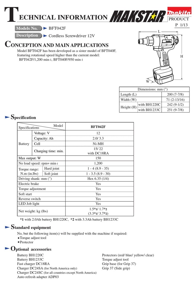
Makita FS4300 Manual

PRODUCT
P 1/ 7
Specification
Standard equipment
FS4300, FS4200, FS4200A, FS4200TP, FS4000
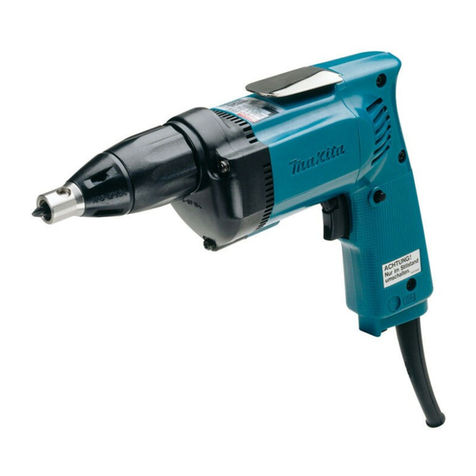
Drywall Screwdriver
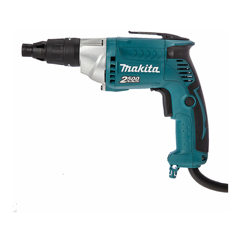
The five models in the subject are drywall screwdrivers
well balanced for easy handling and maneuverability,
featuring the following main benefits;
Best possible tool body for screwdriving
One-touch locator
More durable belt clip
LED job light (except for FS4000)
See the table of “Specification” for the specification
differences between the five models.
FS4300, FS4200, FS4000 are also available with
plastic carrying case as
Model FS4300K, FS4200K, FS4000K.
Dimensions: mm (")
Width (W)
Height (H)
*for countries where noise suppressing device is required
to conform to regulations
with connect bit 76
with connect bit 60
Length (L) 293 (11-1/2) 284 (11-1/8)
279 (11) 269 (10-5/8)
FS4300
FS4200
FS4200A
FS4200TP
FS4000
65 (2-9/16)
207 (8-1/8)*
192 (7-9/16)
Optional accessories
TECHNICAL INFORMATION
Specification
Net weight*: kg (lbs) 1.4 (3.1)
Model FS4200A FS4200TPFS4200 FS4000
Power supply cord
Europe: 4.0 (13.1) ,
Australia/ Chile/
Brazil: 2.0 (6.6),
Other countries: 2.5 (8.2)
Europe: 4.0 (13.1),
Australia/
Brazil: 2.0 (6.6),
Other countries: 2.5 (8.2)
Europe: 4.0 (13.1),
Australia/
Brazil: 2.0 (6.6),
Other countries: 2.5 (8.2)
15 (50) 15 (50)
Twist lock plug type
FS4300
Phillips insert bit 2-25 .............................................................. 2
Magnetic connect bit 6.35-60 or 6.35-76 ............................... 1
Plastic carrying case (FS4300K, FS4200K, FS4000K only) ......... 1
Continuous Rating (W)
Voltage (V) Cycle (Hz) Input Output Max. Output (W)
110
120
220
230
240
5.5
6.0
2.7
2.6
2.5
50/60
50/60
50/60
50/60
50/60
570
---
570
570
570
260
360
260
260
260
500
500
500
500
500
Current (A)
Note: The standard equipment for the tool shown above may vary by country.
Phillips insert bits 1-25, 2-25, 3-25
Magnetic connect bit 6.35-60
Magnetic connect bit 6.35-76
5 (3/16)
6 (1/4)
Drywall screw
Self drilling screw
0 - 4,000No load speed: min.-1 = rpm
Driving shank: mm (")
Capacity: mm (")
Reverse switch
Protection against electric shock
6.35 (1/4) Hex
Yes
Variable speed control by trigger Yes
Silent clutch No NoNo NoYes
LED job light Yes Yes NoYes Yes
Double insulation by Grounding
Double insulation
*Weight according to EPTA-Procedure 01/2003
North America: 1.4 (3.0)
Other countries: 1.4 (3.1)
North America: 1.3 (2.8)
Other countries: 1.3 (2.9)
Model No.
Description
CONCEPT AND MAIN APPLICATIONS
L
H
W
FS4300 FS4200
FS4000
Type Normal type Normal type Normal typeLong type
Length: m (ft)
[2] LUBRICATION
Repair
Apply the following grease to protect parts and product from unusual abrasion.
* Makita grease FA No.2 to;
Gear teeth (Place A: 2.5g) Cam portion (Place B: 1g) Contact portions (Designated by arrows: a little)

* Lubricant VG100 to thread portion of Lock ring (Place C: a little)
* Lubricant VG32 to Flat washers 8 (Place D: a little) for FS4300 only
P 2/ 7
CAUTION: Repair the machine in accordance with “Instruction manual” or “Safety instructions”.
Fig. 1
FS4300
A: 2.5g
B: 1g
C
D
FS4000, FS4200,
FS4200A, FA4200TP
A: 2.5g
Lock ring
Compression spring 8
Flat washer 8
(2pcs.)
Spindle 125N Helical gear 41N Thrust needle cage 821
Spindle 125S
complete
Needle bearing
509 (Component
of Spindle 125S)
Dust seal 13
(Component of
Gear housing)
Locator complete
Plane bearing 14
(Component of Gear housing)
Compression spring 6
B: 1g
Gear 41S
complete
C
[1] REPAIRING TOOL
DescriptionCode No. Use for
Bearing extractor1R269 Removing Ball bearings

[3] DIFFERENCE OF CLUTCH BETWEEN FS4000, FS4200(A/TP) AND AND FS4300
Repair
P 3/ 7
Fig. 2
FS4000
FS4200
FS4200A
FS4200TP
FS4300
Spindle 125N
Compression
spring 8
Compression spring 6
Helical gear 41N
Gear 41S complete
Collared pin 8
[1] REPAIRING TOOL
CAUTION: Repair the machine in accordance with “Instruction manual” or “Safety instructions”.
FS4000
Steel ball 4
(3pcs.)
Clutch cam 125S
Flat washer 8 (2pcs.)
FS4000: Gear housing HP complete
FS4200, FS4200A, FS4200TP: Gear housing HNP complete
FS4300: Gear housing HSB complete
Spindle 125S
complete
[4] DISASSEMBLY/ ASSEMBLY
[4]-1. Clutch portion (cont.)
FS4000, FS4200, FS4200A, FS4200TP
Fig. 4
FS4300
Fig. 3
1) After removing Locator and Lock ring, remove Connect bit.
2) Remove three 4x30 Tapping screws. (Fig. 3)
While holding Gear housing cover complete not to separate from
Motor housing,
remove Gear housing complete from Gear housing cover complete.
3) Clutch portion can be removed. See Fig. 4.
DISASSEMBLING
Steel ball 3.5 Steel ball 3.5
Spindle 125N Spindle 125S complete
Compression spring 6
Leaf spring
Leaf spring
Collared pin 8
Stopper
Flat area
cylindrical end
Thrust needle cage 821 Thrust needle cage 821
Washer 821 Washer 821
Helical gear 41N
Cam portion
Compression spring 8
Flat washer 8 (2pcs.)
Clutch cam 125S
Steel ball 4 (3pcs.)
Spur gear 41S complete
Gear housing
(HNB/ HSB HP)
complete
Gear housing cover complete
Motor
housing
4x30 Tapping
screw (3pcs.)

Repair
P 4/ 7
[4] DISASSEMBLY/ ASSEMBLY
[4]-1. Clutch portion (cont.)
[1] REPAIRING TOOL
CAUTION: Repair the machine in accordance with “Instruction manual” or “Safety instructions”.
FS4000
Fig. 5
1) Face the cylindrical end of Collared pin 8 to the cam portion of
Helical gear 41N, and press-fit Collared pin 8 into Helical gear 41N
until it stops by the stopper as illustrated in Figs. 5 and 1.
2) Take the disassembling step in reverse to assemble the remaining parts
to Collared pin 8 with Helical gear 41N.
Note: Compression spring 6 has to be set between the bottom of Spindle
hole and one end of Collared pin 8. Refer to Figs. 4 and 1 and pay
attention to the direction of Collared pin 8.
Do not assemble Washer 821 and Thrust needle cage 821 to
Helical gear 41N in the wrong order.
ASSEMBLING (FS4000, FS4200, FS4200A, FS4200TP)
ASSEMBLING (FS4300)
Collared pin 8
Cam portion
Flat area
Stopper
cylindrical
end
Flat portion
Helical
gear 41N
Fig. 7
Fig. 6
Fig. 9Fig. 8
Top of Compression spring 8 reaches the rim of Needle bearing 509 (Re: Fig. 1)
in Spindle 125S complete.
Note: Do not interrupt the work of Needle bearing 509.
1) Mount Compression spring 8 on Needle bearing 509 in Spindle 125S complete by pushing Compression spring 8 into
Spindle 125S complete using the thick shaft end of Gear 41S complete temporarily and turning the thin shaft clockwise.
(Figs. 6)
2) Assemble Thrust needle cage 821 and Washer 821 to the thick shaft side of Gear 41S complete. (Fig. 7)
3) Attach three Steel balls 4 on the reverse of Clutch cam 125S with Makita grease FA No. 2, and then assemble them to
the thin shaft side of Gear 41S complete. (Fig. 8)
4) Mount two Flat washers 8 on Clutch cam through the thin shaft of Gear 41S complete. (Fig. 9)
5) Insert the thin shaft of Gear 41S complete into Spindle 125S complete through Compression spring 8. (Figs. 4 and 1)
Thrust needle
cage 821
Washer 821
Thick shaft side of
Gear 41S complete
Thick shaft end of
Gear 41S complete
Thin shaft side
of Gear 41S complete
Thin shaft side
of Gear 41S
complete
Thin shaft side of
Gear 41S complete
Steel ball 4
(3pcs.)
Reverse of Clutch cam 125S Clutch cam 125S
Flat washer 8
(2pcs.)

[4] DISASSEMBLY/ ASSEMBLY
[4]-3. Replacing Armature
Repair
P 5/ 7
Fig. 13Fig. 12
Fig. 15
Fig. 14
1) Loosen three 4x25 Tapping screws and remove Handle cover complete and Carbon brushes. (Fig. 12)
2) Loosen three 4x30 Tapping screws and remove the assembled parts of Gear housing, Gear housing cover and Armature
from Motor housing. (Fig. 13)
3) Remove Armature ass’y with Labyrinth rubber ring from Gear housing cover.
Armature ass’y can be disassembled as illustrated in Fig. 14. Use 1R269.
4) Take the disassembling step in reverse.
Note: Be sure to face the depressed portion of Ring 7 to Armature shaft gear end. (Fig. 15) Markings of “>PC<” “7”
are shown on the depressed portion.
4x25 Tapping
screw (3pcs.)
4x30 Tapping
screw (3pcs.)
Gear housing
cover complete
Gear housing
complete
Handle cover
complete
Motor
housing
Ring 7 (viewed
from flat side)
Ring 7 (viewed from depressed side)
Insulation
washer
Ball bearing 608VV
Ball bearing
607ZZ
Armature ass’y
Armature ass’y
Fan 52 Labyrinth
rubber ring
>PC< 7
(marking)
Armature gear
shaft end
(marking)
Fan 52Ball bearing 608VV
Fig. 10 Fig. 11
1) Face the ends of Ring spring 33 to the left side when holding the machine as illustrated in Fig. 10, and fit Ring spring 33
into the groove on Gear housing complete.
2) Face the ends of Leaf spring to the right side when holding the machine as illustrated in Fig. 11, and hook the carved
ends of Leaf spring with the ribs of Gear housing complete.
Viewed from left side
Viewed from right side
Carved end of
Leaf spring
Protrusions of Gear housing complete
Ribs of Gear housing complete
to hook Leaf spring
Groove on
Gear housing
complete
Ends of
Ring spring
33
[4]-2. Assembling of Ring spring 33 and Leaf spring

P 6/ 7
Fig. D-1
Circuit diagram
Color index of lead wires' sheath
Black
White
Orange
Blue
Purple
Transparent
Earth terminal
for Noise
suppressor
Areas where suppression of
radio interference is required
Areas where suppression of
radio interference is required
Light circuit
(except FS4000)
Light circuit
(except FS4000)
Field
Brush
holder
Switch
Brush
holder
Field
Brush
holder
Brush
holder
Brown
lead wire
is used
for some
countries.
Blue lead wire is used
for some countries.
Blue lead wire is used
for some countries.
Blue lead wire
is used for some
countries.
(To connect with Field laminations)
Noise
suppressor
Connector
2-SD
Power
supply cord
Power supply cord
Brown
lead wire
is used
for some
countries.
Choke coil

P 7/ 7
Wiring diagram
Fig. D-2
Light circuit
(Except FS4000)
Strain relief*
Insert Lead wires of Light circuit into grooves of
Motor housing before clamping Power supply cord
with Strain relief* and two 4x18 Tapping screws.
(Except FS4300TP)
Put the Lead wire’s slack of
Earth terminal in this space.
(Earth terminal is not used
for areas where suppression
of radio interference is not
required.)
Fix Lead wire of Earth terminal with Lead wire holders.
(Earth terminal is not used for areas where suppression of radio interference is not required.)
Fix Lead wires which are passed
right and left around here, with
Lead wire holders designated by a circle.
Put Noise suppressor here.
(Noise suppressor is not
used for areas where
suppression of radio
interference is not required.)
Brush holderBrush holder
Fix Lead wire with
Lead wire holders.
Fix Lead wire with
Lead wire holders.
* Note: Some specifications do not
have Strain relief.
This manual suits for next models
4
Table of contents
Other Makita Power Screwdriver manuals

Makita
Makita BFL400F User manual

Makita
Makita DFS250 User manual

Makita
Makita FS4000 User manual

Makita
Makita DFS452 User manual

Makita
Makita 6823N User manual

Makita
Makita 6826 User manual

Makita
Makita 6805BV User manual

Makita
Makita DA001G User manual

Makita
Makita DFS441 User manual

Makita
Makita DDA340 User manual

Makita
Makita FS2500 User manual

Makita
Makita DFT043F User manual

Makita
Makita GAD01 User manual

Makita
Makita BDA351 User manual

Makita
Makita BFL300F User manual

Makita
Makita DFL020F User manual

Makita
Makita ELECTRIC BRAKE 6094DW User manual

Makita
Makita BDA341 User manual

Makita
Makita DFL061F User manual

Makita
Makita DFT044F User manual