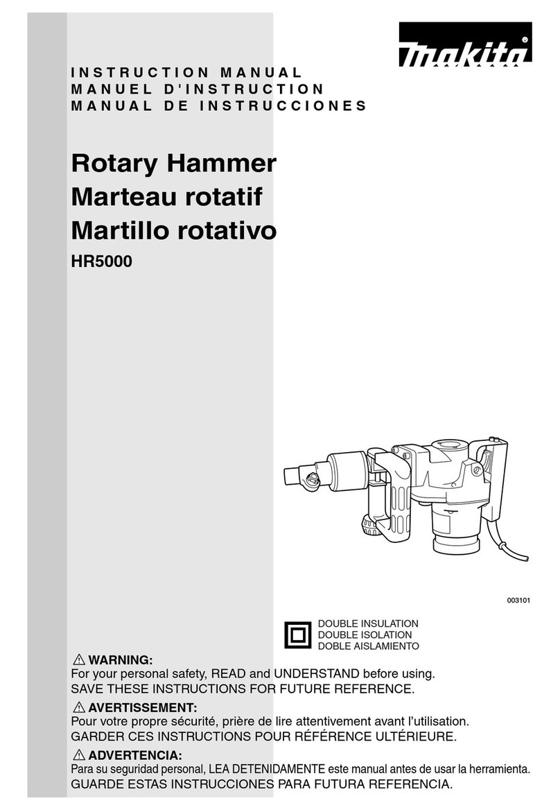
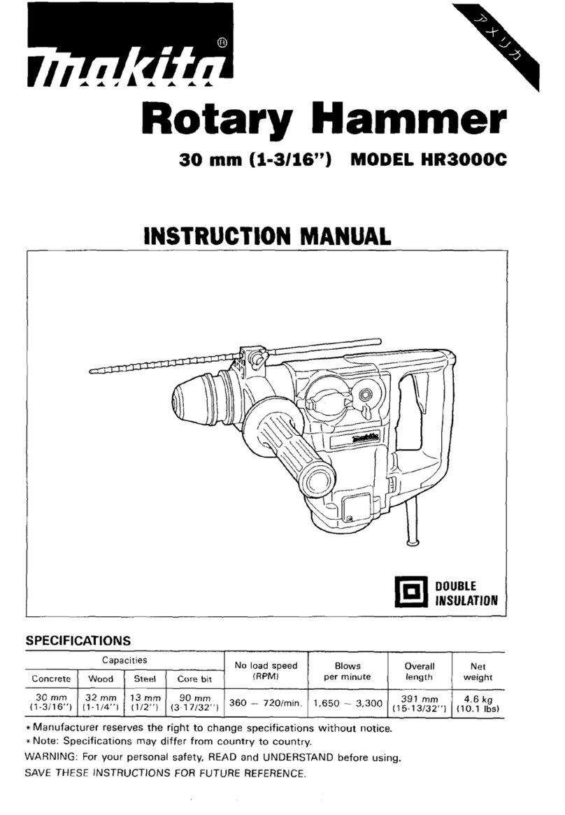
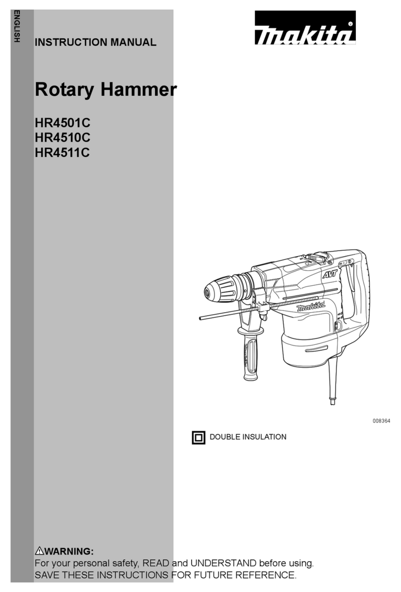
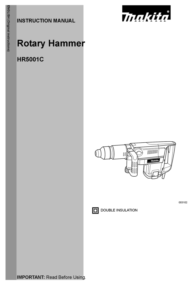
Makita DHR400 User manual

DHR400
EN Cordless Rotary Hammer INSTRUCTION MANUAL 9
FR Perforateur Sans Fil MANUEL D’INSTRUCTIONS 20
DE Akku-Bohrhammer BETRIEBSANLEITUNG 31
IT Martello rotativo a batteria ISTRUZIONI PER L’USO 43
NL Accuboorhamer GEBRUIKSAANWIJZING 55
ES Martillo Rotativo Inalámbrico MANUAL DE
INSTRUCCIONES 67
PT Martelete Rotativo a Bateria MANUAL DE INSTRUÇÕES 79
DA Akku-borehammer BRUGSANVISNING 90
EL Φορητό σφυροτρύπανο ΕΓΧΕΙΡΙΔΙΟ ΟΔΗΓΙΩΝ 101
TR Akülü Kırıcı Delici KULLANMA KILAVUZU 113

1
2
3
Fig.1
1
2
Fig.2
BA
2
1
Fig.3
1
Fig.4
1
Fig.5
1
2
Fig.6
1
2
Fig.7
Fig.8
2

1
2
Fig.9
1
Fig.10
1
2
Fig.11
1
Fig.12
1
2
Fig.13
1 2
Fig.14
1 2
Fig.15
3

12
Fig.16
1
2
3
Fig.17
1
2
34
Fig.18
1
2
Fig.19
1
Fig.20
1
Fig.21
4

1
2
3
Fig.22
1
2
3
Fig.23
1
2
Fig.24
12 3
3
Fig.25
(1)
Fig.26
Fig.27
Fig.28
5

Fig.29
Fig.30
1
Fig.31
1
2
3
4
Fig.32
1
2
3
Fig.33
1
Fig.34
6

1 2
1
2
Fig.35
Fig.36
1
Fig.37
12
Fig.38
1
Fig.39
1
Fig.40
7

1 2
1
2
Fig.41
8

9ENGLISH
ENGLISH (Original instructions)
SPECIFICATIONS
Model: DHR400
Capacities Carbide-tipped bit 40 mm
Core bit 105 mm
No load speed (RPM) 250 - 500 min-1
Blows per minute 1,450 - 2,900 min-1
Overall length 473 mm
Rated voltage D.C. 36 V
Net weight 7.3 - 8.1 kg
• Duetoourcontinuingprogramofresearchanddevelopment,thespecicationshereinaresubjecttochange
without notice.
• Specicationsandbatterycartridgemaydifferfromcountrytocountry.
• Theweightmaydifferdependingontheattachment(s),includingthebatterycartridge.Thelightestandheavi-
estcombination,accordingtoEPTA-Procedure01/2014,areshowninthetable.
Applicable battery cartridge
BL1815N/BL1820/BL1820B/BL1830/BL1830B/BL1840/BL1840B/BL1850/BL1850B/BL1860B
• Someofthebatterycartridgeslistedabovemaynotbeavailabledependingonyourregionofresidence.
WARNING: Only use the battery cartridges listed above.Useofanyotherbatterycartridgesmaycause
injuryand/orre.
Intended use
Thetoolisintendedforhammerdrillinganddrillingin
brick,concreteandstoneaswellasforchisellingwork.
Noise
ThetypicalA-weightednoiseleveldeterminedaccord-
ing to EN60745:
Soundpressurelevel(LpA):91dB(A)
Soundpowerlevel(LWA):102dB(A)
Uncertainty(K):3dB(A)
WARNING: Wear ear protection.
Vibration
Thevibrationtotalvalue(tri-axialvectorsum)deter-
mined according to EN60745:
Work mode: hammer drilling into concrete
Vibration emission (ah, HD):5.0m/s2
Uncertainty(K):1.5m/s2
Workmode:chisellingfunctionwithsidegrip
Vibration emission (ah, Cheq):4.5m/s2
Uncertainty(K):1.5m/s2
Workmode:chisellingfunctionwithsidehandle
Vibration emission (ah, Cheq):4.5m/s2
Uncertainty(K):1.5m/s2
NOTE:Thedeclaredvibrationemissionvaluehas
been measured in accordance with the standard test
methodandmaybeusedforcomparingonetoolwith
another.
NOTE:Thedeclaredvibrationemissionvalue
mayalsobeusedinapreliminaryassessmentof
exposure.
WARNING:
Thevibrationemissionduringactual
useofthepowertoolcandifferfromthedeclaredemission
valuedependingonthewaysinwhichthetoolisused.
WARNING:Besuretoidentifysafetymeasures
to protect the operator that are based on an estima-
tionofexposureintheactualconditionsofuse(taking
accountofallpartsoftheoperatingcyclesuchas
thetimeswhenthetoolisswitchedoffandwhenitis
running idle in addition to the trigger time).
EC Declaration of Conformity
For European countries only
TheECdeclarationofconformityisincludedasAnnexA
to this instruction manual.
SAFETY WARNINGS
General power tool safety warnings
WARNING: Read all safety warnings, instruc-
tions, illustrations and specications provided
with this power tool.Failuretofollowallinstructions
listedbelowmayresultinelectricshock,reand/or
seriousinjury.
Save all warnings and instruc-
tions for future reference.
Theterm"powertool"inthewarningsreferstoyour
mains-operated(corded)powertoolorbattery-operated
(cordless) power tool.

10 ENGLISH
CORDLESS ROTARY HAMMER
SAFETY WARNINGS
1. Wear ear protectors.Exposuretonoisecan
cause hearing loss.
2. Use auxiliary handle(s), if supplied with the
tool.Lossofcontrolcancausepersonalinjury.
3. Hold power tool by insulated gripping sur-
faces, when performing an operation where
the cutting accessory may contact hidden
wiring.Cuttingaccessorycontactinga"live"
wiremaymakeexposedmetalpartsofthepower
tool"live"andcouldgivetheoperatoranelectric
shock.
4. Wear a hard hat (safety helmet), safety glasses
and/or face shield. Ordinary eye or sun glasses
are NOT safety glasses. It is also highly recom-
mended that you wear a dust mask and thickly
padded gloves.
5. Be sure the bit is secured in place before
operation.
6. Under normal operation, the tool is designed
to produce vibration. The screws can come
loose easily, causing a breakdown or accident.
Check tightness of screws carefully before
operation.
7. In cold weather or when the tool has not been
used for a long time, let the tool warm up for
a while by operating it under no load. This
will loosen up the lubrication. Without proper
warm-up, hammering operation is difcult.
8. Always be sure you have a rm footing. Be
sure no one is below when using the tool in
high locations.
9. Hold the tool rmly with both hands.
10. Keep hands away from moving parts.
11. Do not leave the tool running. Operate the tool
only when hand-held.
12. Do not point the tool at any one in the area
when operating. The bit could y out and
injure someone seriously.
13. Do not touch the bit, parts close to the bit, or
workpiece immediately after operation; they
may be extremely hot and could burn your
skin.
14. Some material contains chemicals which may
be toxic. Take caution to prevent dust inhala-
tion and skin contact. Follow material supplier
safety data.
15. Always be sure that the tool is switched
off and the battery cartridge and the bit are
removed before handing the tool to other
person.
SAVE THESE INSTRUCTIONS.
WARNING: DO NOT let comfort or familiarity
with product (gained from repeated use) replace
strict adherence to safety rules for the subject
product. MISUSE or failure to follow the safety
rules stated in this instruction manual may cause
serious personal injury.
Important safety instructions for
battery cartridge
1. Before using battery cartridge, read all instruc-
tions and cautionary markings on (1) battery
charger, (2) battery, and (3) product using
battery.
2. Do not disassemble battery cartridge.
3. If operating time has become excessively
shorter, stop operating immediately. It may
result in a risk of overheating, possible burns
and even an explosion.
4. If electrolyte gets into your eyes, rinse them
out with clear water and seek medical atten-
tion right away. It may result in loss of your
eyesight.
5. Do not short the battery cartridge:
(1) Do not touch the terminals with any con-
ductive material.
(2) Avoid storing battery cartridge in a con-
tainer with other metal objects such as
nails, coins, etc.
(3) Do not expose battery cartridge to water
or rain.
A battery short can cause a large current
ow, overheating, possible burns and even a
breakdown.
6. Do not store the tool and battery cartridge in
locations where the temperature may reach or
exceed 50 °C (122 °F).
7. Do not incinerate the battery cartridge even if
it is severely damaged or is completely worn
out. The battery cartridge can explode in a re.
8. Be careful not to drop or strike battery.
9. Do not use a damaged battery.
10. The contained lithium-ion batteries are subject
to the Dangerous Goods Legislation require-
ments.
Forcommercialtransportse.g.bythirdparties,
forwardingagents,specialrequirementonpack-
aging and labeling must be observed.
Forpreparationoftheitembeingshipped,consult-
inganexpertforhazardousmaterialisrequired.
Pleasealsoobservepossiblymoredetailed
national regulations.
Tapeormaskoffopencontactsandpackupthe
batteryinsuchamannerthatitcannotmove
around in the packaging.
11. Follow your local regulations relating to dis-
posal of battery.
12. Use the batteries only with the products
specied by Makita. Installing the batteries to
non-compliantproductsmayresultinare,exces-
siveheat,explosion,orleakofelectrolyte.
SAVE THESE INSTRUCTIONS.
CAUTION: Only use genuine Makita batteries.
Useofnon-genuineMakitabatteries,orbatteriesthat
havebeenaltered,mayresultinthebatterybursting
causingres,personalinjuryanddamage.Itwill
alsovoidtheMakitawarrantyfortheMakitatooland
charger.
11 ENGLISH
Tips for maintaining maximum
battery life
1. Charge the battery cartridge before completely
discharged. Always stop tool operation and
charge the battery cartridge when you notice
less tool power.
2.
Never recharge a fully charged battery cartridge.
Overcharging shortens the battery service life.
3.
Charge the battery cartridge with room tempera-
ture at 10 °C - 40 °C (50 °F - 104 °F). Let a hot
battery cartridge cool down before charging it.
4. Charge the battery cartridge if you do not use
it for a long period (more than six months).
Important safety instructions for
wireless unit
1. Do not disassemble or tamper with the wire-
less unit.
2. Keep the wireless unit away from young chil-
dren. If accidentally swallowed, seek medical
attention immediately.
3. Use the wireless unit only with Makita tools.
4. Do not expose the wireless unit to rain or wet
conditions.
5. Do not use the wireless unit in places where
the temperature exceeds 50°C (122°F).
6. Do not operate the wireless unit in places
where medical instruments, such as heart
pace makers are near by.
7.
Do not operate the wireless unit in places where
automated devices are near by.Ifoperated,auto-
mateddevicesmaydevelopmalfunctionorerror.
8.
The wireless unit can produce electromagnetic
elds (EMF) but they are not harmful to the user.
9. The wireless unit is an accurate instrument. Be
careful not to drop or strike the wireless unit.
10. Avoid touching the terminal of the wireless
unit with bare hands or metallic materials.
11. Always remove the battery on the tool when
installing the wireless unit.
12. When opening the lid of the slot, avoid the
place where dust and water may come into the
slot. Always keep the inlet of the slot clean.
13. Always insert the wireless unit in the correct
direction.
14. Do not press the wireless activation button
on the wireless unit too hard and/or press the
button with an object with a sharp edge.
15.
Always close the lid of the slot when operating.
16.
Do not remove the wireless unit from the slot
while the power is being supplied to the tool.
Doingsomaycauseamalfunctionofthewirelessunit.
17. Do not remove the sticker on the wireless unit.
18. Do not put any sticker on the wireless unit.
19.
Do not leave the wireless unit in a place where static
electricity or electrical noise could be generated.
20.
Do not leave the wireless unit in a place subject
to high heat, such as a car sitting in the sun.
21. Do not leave the wireless unit in a dusty or
powdery place or in a place corrosive gas
could be generated.
22. Sudden change of the temperature may bedew
the wireless unit. Do not use the wireless unit
until the dew is completely dried.
23. When cleaning the wireless unit, gently wipe
with a dry soft cloth. Do not use benzine, thin-
ner, conductive grease or the like.
24. When storing the wireless unit, keep it in the
supplied case or a static-free container.
25. Do not insert any devices other than Makita
wireless unit into the slot on the tool.
26. Do not use the tool with the lid of the slot dam-
aged.Water,dust,anddirtcomeintotheslotmay
causemalfunction.
27. Do not pull and/or twist the lid of the slot more
than necessary.Restorethelidifitcomesoff
fromthetool.
28. Replace the lid of the slot if it is lost or
damaged.
SAVE THESE INSTRUCTIONS.
FUNCTIONAL
DESCRIPTION
CAUTION: Always be sure that the tool is
switched off and the battery cartridge is removed
before adjusting or checking function on the tool.
Installing or removing battery
cartridge
CAUTION: Always switch off the tool before
installing or removing of the battery cartridge.
CAUTION: Hold the tool and the battery car-
tridge rmly when installing or removing battery
cartridge.Failuretoholdthetoolandthebattery
cartridgermlymaycausethemtoslipoffyourhands
andresultindamagetothetoolandbatterycartridge
andapersonalinjury.
►Fig.1: 1. Red indicator 2. Button 3.Batterycartridge
Toremovethebatterycartridge,slideitfromthetool
whileslidingthebuttononthefrontofthecartridge.
Toinstallthebatterycartridge,alignthetongueonthe
batterycartridgewiththegrooveinthehousingandslip
itintoplace.Insertitallthewayuntilitlocksinplace
withalittleclick.Ifyoucanseetheredindicatoronthe
uppersideofthebutton,itisnotlockedcompletely.
CAUTION: Always install the battery cartridge
fully until the red indicator cannot be seen.Ifnot,
itmayaccidentallyfalloutofthetool,causinginjuryto
youorsomeonearoundyou.
CAUTION: Do not install the battery cartridge
forcibly.Ifthecartridgedoesnotslideineasily,itis
notbeinginsertedcorrectly.

12 ENGLISH
Indicating the remaining battery
capacity
Only for battery cartridges with the indicator
►Fig.2: 1. Indicator lamps 2. Check button
Pressthecheckbuttononthebatterycartridgetoindi-
catetheremainingbatterycapacity.Theindicatorlamps
lightupforafewseconds.
Indicator lamps Remaining
capacity
Lighted Off Blinking
75% to 100%
50% to 75%
25% to 50%
0% to 25%
Charge the
battery.
Thebattery
mayhave
malfunctioned.
NOTE:Dependingontheconditionsofuseandthe
ambienttemperature,theindicationmaydifferslightly
fromtheactualcapacity.
Tool / battery protection system
Thetoolisequippedwithatool/batteryprotectionsys-
tem.Thissystemautomaticallycutsoffpowertothe
motortoextendtoolandbatterylife.Thetoolwillauto-
maticallystopduringoperationifthetoolorbatteryis
placedunderoneofthefollowingconditions:
Overload protection
Whenthebatteryisoperatedinamannerthatcauses
ittodrawanabnormallyhighcurrent,thetoolautomat-
icallystopswithoutanyindication.Inthissituation,turn
thetooloffandstoptheapplicationthatcausedthetool
tobecomeoverloaded.Thenturnthetoolontorestart.
Overheat protection
Whenthetoolorbatteryisoverheated,thetoolstops
automaticallyandthelampblinks.Inthiscase,letthe
toolandbatterycoolbeforeturningthetoolonagain.
Overdischarge protection
Whenthebatterycapacityisnotenough,thetoolstops
automatically.Inthiscase,removethebatteryfromthe
toolandchargethebattery.
Switch action
WARNING: Before installing the battery car-
tridge into the tool, always check to see that the
switch trigger actuates properly and returns to
the "OFF" position when released.
CAUTION: When not operating the tool,
depress the trigger-lock button from side to
lock the switch trigger in the OFF position.
►Fig.3: 1.Switchtrigger2.Trigger-lockbutton
Topreventtheswitchtriggerfromaccidentallypulled,
thetrigger-lockbuttonisprovided.Tostartthetool,
depressthetrigger-lockbuttonfromAsideandpullthe
switchtrigger.Releasetheswitchtriggertostop.After
use,pressinthetrigger-lockbuttonfromBside.
Speed change
Therevolutionsandblowsperminutecanbeadjusted
byturningtheadjustingdial.Thedialismarked1(low-
estspeed)to5(fullspeed).
►Fig.4: 1.Adjustingdial
Refertothetablebelowfortherelationshipbetweenthe
numberontheadjustingdialandtherevolutionsand
blows per minute.
Number Revolutions per
minute
Blows per minute
5500 2,900
4470 2,700
3380 2,150
2290 1,650
1250 1,450
CAUTION: Do not turn the adjusting dial when
the tool is running. Failure to do so may result in
the loss of control of the tool and cause an injury.
NOTICE: If the tool is operated continuously at
low speed for a long time, the motor will get over-
loaded, resulting in tool malfunction.
NOTICE: The speed adjusting dial can be turned
only as far as 5 and back to 1. Do not force it past
5 or 1, or the speed adjusting function may no
longer work.
NOTE:Whenthespeedadjustingdialissetto"3"or
higher,thetoolautomaticallyreducesthespeedat
no-load to reduce the vibration under no-load. Once
operation starts with a bit against concrete, blows per
minute increase and reach the numbers as shown in
the table. When temperature is low and there is less
uidityingrease,thetoolmaynothavethisfunction
even with the motor rotating.

13 ENGLISH
Lighting up the front lamp
►Fig.5: 1. Lamp
CAUTION: Do not look in the light or see the
source of light directly.
Pulltheswitchtriggertolightupthelamp.Thelamp
keeps on lighting while the switch trigger is being pulled.
Thelampgoesoutapproximately10secondsafter
releasing the switch trigger.
NOTE:Useadryclothtowipethedirtoffthelensof
thelamp.Becarefulnottoscratchthelensoflamp,or
itmaylowertheillumination.
Selecting the action mode
NOTICE: Do not rotate the action mode chang-
ing knob when the tool is running.Thetoolwillbe
damaged.
NOTICE: To avoid rapid wear on the mode
change mechanism, be sure that the action mode
changing knob is always positively located in one
of the three action mode positions.
Rotation with hammering
Fordrillinginconcrete,masonry,etc.,rotatetheaction
mode changing knob to the symbol.Useacar-
bide-tipped drill bit.
►Fig.6: 1.Actionmodechangingknob2. Pointer
Hammering only
For chipping, scaling or demolition operations, rotate
the action mode changing knob to the symbol.Usea
bull point, cold chisel, scaling chisel, etc.
►Fig.7: 1. Pointer 2.Actionmodechangingknob
Torque limiter
NOTICE: As soon as the torque limiter actuates,
switch off the tool immediately.Thiswillhelppre-
ventprematurewearofthetool.
NOTICE: Drill bits such as hole saw, which tend
to pinch or catch easily in the hole, are not appro-
priate for this tool.Thisisbecausetheywillcause
thetorquelimitertoactuatetoofrequently.
Thetorquelimiterwillactuatewhenacertaintorque
levelisreached.Themotorwilldisengagefromthe
outputshaft.Whenthishappens,thedrillbitwillstop
turning.
Constant speed control
Electronicspeedcontrolforobtainingconstantspeed.
Possibletogetnenish,becausetherotatingspeedis
kept constant even under load condition.
ASSEMBLY
CAUTION: Always be sure that the tool is
switched off and the battery cartridge is removed
before carrying out any work on the tool.
Side handle
►Fig.8
CAUTION: Use the side handle only when
chipping, scaling or demolishing. Do not use it
when drilling in concrete, masonry, etc.Thetool
cannotbeheldproperlywiththissidehandlewhen
drilling.
►Fig.9: 1.Sidehandle2. Clamp nut
Thesidehandlecanbeswung360°onthevertical
andsecuredatanydesiredposition.Italsosecures
ateightdifferentpositionsbackandforthonthehori-
zontal.Loosentheclampnuttoswingthesidehandle
to a desired position, and then tighten the clamp nut
securely.
Side grip (auxiliary handle)
CAUTION: Always use the side grip to ensure
safe operation.
CAUTION: After installing or adjusting the
side grip, make sure that the side grip is rmly
secured.
Thesidegripswingsaroundtoeitherside,allowing
easyhandlingofthetoolinanyposition.Loosenthe
sidegripbyturningitcounterclockwise,swingittothe
desiredpositionandthentightenitbyturningclockwise.
►Fig.10: 1.Sidegrip
Grease
Coattheshankendofthedrillbitbeforehandwitha
smallamountofgrease(about0.5-1g).
Thischucklubricationassuressmoothactionandlon-
gerservicelife.
Installing or removing drill bit
Cleantheshankendofthedrillbitandapplygrease
beforeinstallingthedrillbit.
►Fig.11: 1.Shankend2. Grease
Insertthedrillbitintothetool.Turnthedrillbitandpush
it in until it engages.
Afterinstallingthedrillbit,alwaysmakesurethatthe
drillbitissecurelyheldinplacebytryingtopullitout.
►Fig.12: 1. Drill bit
Toremovethedrillbit,pullthechuckcoverdownallthe
wayandpullthedrillbitout.
►Fig.13: 1. Drill bit 2. Chuck cover

14 ENGLISH
Chisel angle (when chipping,
scaling or demolishing)
Thechiselcanbesecuredatthedesiredangle.To
change the chisel angle, rotate the action mode chang-
ingknobtotheOsymbol.Turnthechiseltothedesired
angle.
►Fig.14: 1.Actionmodechangingknob2. Pointer
Rotate the action mode changing knob to the sym-
bol.Thenmakesurethatthechiselissecurelyheldin
placebyturningitslightly.
Depth gauge
Thedepthgaugeisconvenientfordrillingholesof
uniformdepth.
Press and hold the lock button, and then insert the
depthgaugeintothehexhole.
►Fig.15: 1. Depth gauge 2. Lock button
Makesurethatthetoothedsideofthedepthgauge
facesthemarking.
►Fig.16: 1. Marking 2.Toothedside
Adjustthedepthgaugebymovingitbackandforth
whilepressingthelockbutton.Aftertheadjustment,
release the lock button to lock the depth gauge.
NOTE: Make sure that the depth gauge does not
touchthemainbodyofthetoolwhenattachingit.
Dust extractor attachment
Optional accessory
Installing the dust extractor
attachment
1. Loosen the side grip on the tool.
2. Installthedustcoversothattheclawsofthedust
covertinthegroovesbetweenthetoolandtheside
grip.
►Fig.17: 1. Dust cover 2. Claw 3. Groove
3. Tightenthesidegripsecurely.
4. Setthesuitablebellowsordustcoverextension
foryourwork.Whenyouusebellows,attachthejointto
itstop.Whenyoustacktwobellows,connectthemwith
thejoint.
►Fig.18: 1.Dustcoverextension2. Dust cover
3. Joint 4. Bellows
Connecting the tool to the vacuum
cleaner
1. Attachtheholderjointtothetool,andthenattach
thehoseholdertotheholderjoint.
►Fig.19: 1.Holderjoint2. Hose holder
2. Fixthehosetothehoseholder.
►Fig.20: 1. Hose holder
NOTE:Usejoint25toconnectthehoseandthedust
coverifnecessary.
Using depth gauge for drilling
operation
Whenyoustacktwobellows,attachthedepthgauge
extensiontothedepthgauge.
►Fig.21: 1.Depthgaugeextension
Dust extractor attachment (for
hammering only)
Optional accessory
1. Install the hose holder.
When the side handle is installed to tool, loosen the
clampnut,andthenremovethehexbolt.Installthe
hoseholderwiththehexboltandtheclampnutby
tighteningtheclampnutrmly.
►Fig.22: 1. Bolt 2. Hose holder 3. Clamp nut
When the side grip is installed to the tool, loosen the
sidegrip,mountthehoseholdertotheshaft,andthen
tightenthesidegriprmly.
►Fig.23: 1. Hose holder 2.Shaft3.Sidegrip
2. Attachtheholderjointtothetool,andthenattach
thehoseholdertotheholderjoint.
►Fig.24: 1.Holderjoint2. Hose holder
3. Attachthedustcoverandthehosetothetool,and
thenxthehosetothehoseholders.
►Fig.25: 1. Dust cover 2. Hose 3. Hose holder
4. Connectthehosetothehoseofthevacuum
cleanerwiththehosejoint.
NOTE:Ifthehoseisnotincluded,attachthedust
covertothecleaner'sjointorattachittoMakita's
hose ø28.
5. Adjustthedistancebetweenthedustcoverand
thetipofthechiselorbullpoint.Therecommended
distance is 30 mm to 100 mm.
►Fig.26: (1) 30 mm to 100 mm
OPERATION
CAUTION: Always use the side grip (auxiliary
handle) and rmly hold the tool by both side grip
and switch handle during operations.
CAUTION: Always make sure that the work-
piece is secured before operation.
CAUTION: Do not pull the tool out forcibly
even the bit gets stuck. Loss of control may
cause injury.
NOTE:Ifthebatterycartridgeisinlowtemperature,
thetool’scapabilitymaynotbefullyobtained.Inthis
case,warmupthebatterycartridgebyusingthe
toolwithnoloadforawhiletofullyobtainthetool’s
capability.
►Fig.27

15 ENGLISH
Hammer drilling operation
CAUTION:Thereistremendousandsudden
twistingforceexertedonthetool/drillbitatthetimeof
hole break-through, when the hole becomes clogged
withchipsandparticles,orwhenstrikingreinforcing
rods embedded in the concrete. Always use the side
grip (auxiliary handle) and rmly hold the tool by
both side grip and switch handle during opera-
tions.Failuretodosomayresultinthelossofcontrol
ofthetoolandpotentiallysevereinjury.
Settheactionmodechangingknobtothe symbol.
Positionthedrillbitatthedesiredlocationforthehole,
thenpulltheswitchtrigger.Donotforcethetool.Light
pressuregivesbestresults.Keepthetoolinposition
andpreventitfromslippingawayfromthehole.
Donotapplymorepressurewhentheholebecomes
clogged with chips or particles. Instead, run the tool at
anidle,thenremovethedrillbitpartiallyfromthehole.
Byrepeatingthisseveraltimes,theholewillbecleaned
outandnormaldrillingmayberesumed.
NOTE:Eccentricityinthedrillbitrotationmayoccur
whileoperatingthetoolwithnoload.Thetoolauto-
maticallycentersitselfduringoperation.Thisdoesnot
affectthedrillingprecision.
Chipping/Scaling/Demolition
Settheactionmodechangingknobtothe symbol.
Holdthetoolrmlywithbothhands.Turnthetoolon
andapplyslightpressureonthetoolsothatthetoolwill
not bounce around, uncontrolled.
Pressingveryhardonthetoolwillnotincreasethe
efciency.
►Fig.28
Blow-out bulb
Optional accessory
Afterdrillingthehole,usetheblow-outbulbtocleanthe
dustoutofthehole.
►Fig.29
WIRELESS ACTIVATION
FUNCTION
Optional accessory
What you can do with the wireless
activation function
Thewirelessactivationfunctionenablescleanandcom-
fortableoperation.Byconnectingasupportedvacuum
cleanertothetool,youcanrunthevacuumcleaner
automaticallyalongwiththeswitchoperationofthetool.
►Fig.30
Tousethewirelessactivationfunction,preparefollow-
ing items:
• Awirelessunit(optionalaccessory)
• Avacuumcleanerwhichsupportsthewireless
activationfunction
Theoverviewofthewirelessactivationfunction
settingisasfollows.Refertoeachsectionfordetail
procedures.
1. Installing the wireless unit
2. Toolregistrationforthevacuumcleaner
3. Startingthewirelessactivationfunction
Installing the wireless unit
Optional accessory
CAUTION: Place the tool on a at and stable
surface when installing the wireless unit.
NOTICE: Clean the dust and dirt on the tool
before installing the wireless unit. Dust or dirt
maycausemalfunctionifitcomesintotheslotofthe
wireless unit.
NOTICE: To prevent the malfunction caused by
static, touch a static discharging material, such
as a metal part of the tool, before picking up the
wireless unit.
NOTICE: When installing the wireless unit,
always be sure that the wireless unit is inserted
in the correct direction and the lid is completely
closed.
1. Openthelidonthetoolasshowninthegure.
►Fig.31: 1. Lid
2. Insert the wireless unit to the slot and then close
the lid.
Wheninsertingthewirelessunit,aligntheprojections
with the recessed portions on the slot.
►Fig.32: 1. Wireless unit 2.Projection3. Lid
4. Recessed portion
Whenremovingthewirelessunit,openthelidslowly.
Thehooksonthebackofthelidwillliftthewirelessunit
asyoupullupthelid.
►Fig.33: 1. Wireless unit 2. Hook 3. Lid
Afterremovingthewirelessunit,keepitinthesupplied
caseorastatic-freecontainer.
NOTICE: Always use the hooks on the back of
the lid when removing the wireless unit.Ifthe
hooks do not catch the wireless unit, close the lid
completelyandopenitslowlyagain.

16 ENGLISH
Tool registration for the vacuum
cleaner
NOTE:AMakitavacuumcleanersupportingthe
wirelessactivationfunctionisrequiredforthetool
registration.
NOTE: Finish installing the wireless unit to the tool
beforestartingthetoolregistration.
NOTE: During the tool registration, do not pull the
switch trigger or turn on the power switch on the
vacuum cleaner.
NOTE:Refertotheinstructionmanualofthevacuum
cleaner, too.
Ifyouwishtoactivatethevacuumcleaneralongwith
theswitchoperationofthetool,nishthetoolregistra-
tionbeforehand.
1. Install the batteries to the vacuum cleaner and the
tool.
2. Setthestand-byswitchonthevacuumcleanerto
"AUTO".
►Fig.34: 1.Stand-byswitch
3. Press the wireless activation button on the vac-
uumcleanerfor3secondsuntilthewirelessactivation
lampblinksingreen.Andthenpressthewirelessacti-
vationbuttononthetoolinthesameway.
►Fig.35: 1. Wireless activation button 2. Wireless
activation lamp
Ifthevacuumcleanerandthetoolarelinkedsuccess-
fully,thewirelessactivationlampswilllightupingreen
for2secondsandstartblinkinginblue.
NOTE:Thewirelessactivationlampsnishblinking
ingreenafter20secondselapsed.Pressthewireless
activation button on the tool while the wireless acti-
vationlamponthecleanerisblinking.Ifthewireless
activation lamp does not blink in green, push the wire-
lessactivationbuttonbrieyandholditdownagain.
NOTE:Whenperformingtwoormoretoolregistra-
tionsforonevacuumcleaner,nishthetoolregistra-
tiononebyone.
Starting the wireless activation
function
NOTE:Finishthetoolregistrationforthevacuum
cleaner prior to the wireless activation.
NOTE:Refertotheinstructionmanualofthevacuum
cleaner, too.
Afterregisteringatooltothevacuumcleaner,the
vacuumcleanerwillautomaticallyrunsalongwiththe
switchoperationofthetool.
1. Install the wireless unit to the tool.
2. Connectthehoseofthevacuumcleanerwiththe
tool.
►Fig.36
3. Setthestand-byswitchonthevacuumcleanerto
"AUTO".
►Fig.37: 1.Stand-byswitch
4. Push the wireless activation button on the tool
briey.Thewirelessactivationlampwillblinkinblue.
►Fig.38: 1. Wireless activation button 2. Wireless
activation lamp
5. Pulltheswitchtriggerofthetool.Checkifthe
vacuum cleaner runs while the switch trigger is being
pulled.
Tostopthewirelessactivationofthevacuumcleaner,
push the wireless activation button on the tool.
NOTE:Thewirelessactivationlamponthetoolwill
stopblinkinginbluewhenthereisnooperationfor
2hours.Inthiscase,setthestand-byswitchonthe
vacuumcleanerto"AUTO"andpushthewireless
activation button on the tool again.
NOTE:Thevacuumcleanerstarts/stopswithadelay.
Thereisatimelagwhenthevacuumcleanerdetects
aswitchoperationofthetool.
NOTE:Thetransmissiondistanceofthewirelessunit
mayvarydependingonthelocationandsurrounding
circumstances.
NOTE: When two or more tools are registered to one
vacuumcleaner,thevacuumcleanermaystartrun-
ningevenifyoudon'tpulltheswitchtriggerbecause
anotheruserisusingthewirelessactivationfunction.

17 ENGLISH
Description of the wireless activation lamp status
►Fig.39: 1. Wireless activation lamp
Thewirelessactivationlampshowsthestatusofthewirelessactivationfunction.Refertothetablebelowforthe
meaningofthelampstatus.
Status Wireless activation lamp Description
Color
On
Blinking
Duration
Standby Blue 2 hours Thewirelessactivationofthevacuumcleanerisavailable.The
lampwillautomaticallyturnoffwhennooperationisperformed
for2hours.
When
the tool is
running.
Thewirelessactivationofthevacuumcleanerisavailableandthe
tool is running.
Tool
registration
Green 20 seconds Readyforthetoolregistration.Waitingfortheregistrationbythe
vacuum cleaner.
2 seconds Thetoolregistrationhasbeennished.Thewirelessactivation
lamp will start blinking in blue.
Cancelling
tool
registration
Red 20 seconds Readyforthecancellationofthetoolregistration.Waitingforthe
cancellationbythevacuumcleaner.
2 seconds Thecancellationofthetoolregistrationhasbeennished.The
wireless activation lamp will start blinking in blue.
Others Red 3 seconds Thepowerissuppliedtothewirelessunitandthewirelessactiva-
tionfunctionisstartingup.
Off - - Thewirelessactivationofthevacuumcleanerisstopped.
Cancelling tool registration for the
vacuum cleaner
Performthefollowingprocedurewhencancellingthe
toolregistrationforthevacuumcleaner.
1. Install the batteries to the vacuum cleaner and the
tool.
2. Setthestand-byswitchonthevacuumcleanerto
"AUTO".
►Fig.40: 1.Stand-byswitch
3. Press the wireless activation button on the vac-
uumcleanerfor6seconds.Thewirelessactivation
lampblinksingreenandthenbecomered.Afterthat,
press the wireless activation button on the tool in the
sameway.
►Fig.41: 1. Wireless activation button 2. Wireless
activation lamp
Ifthecancellationisperformedsuccessfully,thewire-
lessactivationlampswilllightupinredfor2seconds
and start blinking in blue.
NOTE:Thewirelessactivationlampsnishblinkingin
redafter20secondselapsed.Pressthewirelessacti-
vation button on the tool while the wireless activation
lamponthecleanerisblinking.Ifthewirelessacti-
vation lamp does not blink in red, push the wireless
activationbuttonbrieyandholditdownagain.

18 ENGLISH
Troubleshooting for wireless activation function
Beforeaskingforrepairs,conductyourowninspectionrst.Ifyoundaproblemthatisnotexplainedinthemanual,
donotattempttodismantlethetool.Instead,askMakitaAuthorizedServiceCenters,alwaysusingMakitareplace-
mentpartsforrepairs.
State of abnormality Probable cause (malfunction) Remedy
Thewirelessactivationlampdoes
notlight/blink.
Thewirelessunitisnotinstalledinto
the tool.
Thewirelessunitisimproperlyinstalled
into the tool.
Installthewirelessunitcorrectly.
Theterminalofthewirelessunitand/or
theslotisdirty.
Gentlywipeoffdustanddirtontheterminalofthe
wireless unit and clean the slot.
Thewirelessactivationbuttononthe
tool has not been pushed.
Push the wireless activation button on the tool
briey.
Thestand-byswitchonthevacuum
cleanerisnotsetto"AUTO".
Setthestand-byswitchonthevacuumcleanerto
"AUTO".
Nopowersupply Supplythepowertothetoolandthevacuum
cleaner.
Cannotnishtoolregistration/can-
cellingtoolregistrationsuccessfully.
Thewirelessunitisnotinstalledinto
the tool.
Thewirelessunitisimproperlyinstalled
into the tool.
Installthewirelessunitcorrectly.
Theterminalofthewirelessunitand/or
theslotisdirty.
Gentlywipeoffdustanddirtontheterminalofthe
wireless unit and clean the slot.
Thestand-byswitchonthevacuum
cleanerisnotsetto"AUTO".
Setthestand-byswitchonthevacuumcleanerto
"AUTO".
Nopowersupply Supplythepowertothetoolandthevacuum
cleaner.
Incorrect operation Pushthewirelessactivationbuttonbrieyand
performthetoolregistration/cancellationprocedures
again.
Thetoolandvacuumcleanerisaway
fromeachother(outofthetransmission
range).
Get the tool and vacuum cleaner closer to each
other.Themaximumtransmissiondistanceis
approximately10mhoweveritmayvaryaccording
to the circumstances.
Beforenishingthetoolregistration/
cancellation;
- the switch trigger on the tool is pulled
or;
- the power button on the vacuum
cleaner is turned on.
Pushthewirelessactivationbuttonbrieyand
performthetoolregistration/cancellationprocedures
again.
Thetoolregistrationproceduresforthe
toolorvacuumcleanerhasnotnished.
Performthetoolregistrationproceduresforboththe
tool and the vacuum cleaner at the same timing.
Radiodisturbancebyotherappliances
whichgeneratehigh-intensityradio
waves.
Keepthetoolandvacuumcleanerawayfromthe
appliances such as Wi-Fi devices and microwave
ovens.

19 ENGLISH
State of abnormality Probable cause (malfunction) Remedy
Thevacuumcleanerdoesnotrun
alongwiththeswitchoperationof
the tool.
Thewirelessunitisnotinstalledinto
the tool.
Thewirelessunitisimproperlyinstalled
into the tool.
Installthewirelessunitcorrectly.
Theterminalofthewirelessunitand/or
theslotisdirty.
Gentlywipeoffdustanddirtontheterminalofthe
wireless unit and clean the slot.
Thewirelessactivationbuttononthe
tool has not been pushed.
Pushthewirelessactivationbuttonbrieyandmake
sure that the wireless activation lamp is blinking
in blue.
Thestand-byswitchonthevacuum
cleanerisnotsetto"AUTO".
Setthestand-byswitchonthevacuumcleanerto
"AUTO".
More than 10 tools are registered to the
vacuum cleaner.
Performthetoolregistrationagain.
Ifmorethan10toolsareregisteredtothevacuum
cleaner, the tool registered earliest will be cancelled
automatically.
Thevacuumcleanererasedalltool
registrations.
Performthetoolregistrationagain.
Nopowersupply Supplythepowertothetoolandthevacuum
cleaner.
Thetoolandvacuumcleanerisaway
fromeachother(outofthetransmission
range).
Get the tool and vacuum cleaner closer each other.
Themaximumtransmissiondistanceisapproxi-
mately10mhoweveritmayvaryaccordingtothe
circumstances.
Radiodisturbancebyotherappliances
whichgeneratehigh-intensityradio
waves.
Keepthetoolandvacuumcleanerawayfromthe
appliances such as Wi-Fi devices and microwave
ovens.
Thevacuumcleanerrunswhilethe
tool's switch trigger is not pulled.
Other users are using the wireless
activationofthevacuumcleanerwith
their tools.
Turnoffthewirelessactivationbuttonoftheother
toolsorcancelthetoolregistrationoftheother
tools.
MAINTENANCE
CAUTION: Always be sure that the tool is
switched off and the battery cartridge is removed
before attempting to perform inspection or
maintenance.
NOTICE: Never use gasoline, benzine, thinner,
alcohol or the like. Discoloration, deformation or
cracks may result.
TomaintainproductSAFETYandRELIABILITY,
repairs,anyothermaintenanceoradjustmentshould
beperformedbyMakitaAuthorizedorFactoryService
Centers,alwaysusingMakitareplacementparts.
OPTIONAL
ACCESSORIES
CAUTION: These accessories or attachments
are recommended for use with your Makita tool
specied in this manual.Theuseofanyother
accessoriesorattachmentsmightpresentariskof
injurytopersons.Onlyuseaccessoryorattachment
foritsstatedpurpose.
Ifyouneedanyassistanceformoredetailsregard-
ingtheseaccessories,askyourlocalMakitaService
Center.
• SDS-MAXCarbide-tippeddrillbits
• SDS-MAXbullpoint
• SDS-MAXcoldchisel
• SDS-MAXscalingchisel
• SDS-MAXclayspade
• Hammergrease
• Bitgrease
• Sidehandle
• Sidegrip
• Depthgauge
• Blow-outbulb
• Dustextractorattachment
• Safetygoggles
• Wirelessunit
• Makitagenuinebatteryandcharger
• Plasticcarryingcase
NOTE:Someitemsinthelistmaybeincludedinthe
toolpackageasstandardaccessories.Theymay
differfromcountrytocountry.

20 FRANÇAIS
FRANÇAIS (Instructions originales)
SPÉCIFICATIONS
Modèle : DHR400
Capacités Foret à pointe de carbure 40 mm
Trépan 105 mm
Vitesseàvide(tr/min) 250 - 500 min-1
Frappes par minute 1 450 - 2 900 min-1
Longueur totale 473 mm
Tensionnominale 36 V CC
Poids net 7,3 - 8,1 kg
• Étantdonnél’évolutionconstantedenotreprogrammederechercheetdedéveloppement,lesspécications
contenuesdanscemanuelsontsujettesàmodicationsanspréavis.
• Lesspécicationsetlabatteriepeuventêtredifférentessuivantlespays.
• Lepoidspeutêtredifférentselonlesaccessoires,notammentlabatterie.Lesassociationslapluslégèreetla
pluslourde,conformémentàlaprocédureEPTA01/2014,sontindiquéesdansletableau.
Batterie applicable
BL1815N/BL1820/BL1820B/BL1830/BL1830B/BL1840/BL1840B/BL1850/BL1850B/BL1860B
• Certainesbatteriesrépertoriéesci-dessuspeuventnepasêtredisponiblesselonlarégionoùvousrésidez.
AVERTISSEMENT : N’utilisez que les batteries répertoriées ci-dessus. L’utilisation de n’importe quelle
autrebatteriepeutprovoquerdesblessureset/ouunincendie.
Utilisation prévue
L’outil est conçu pour le perçage avec martelage et le
perçage dans la brique, le béton et la pierre, ainsi que
pour le ciselage.
Bruit
NiveaudebruitpondéréAtypique,déterminéselon
EN60745 :
Niveau de pression sonore (LpA):91dB(A)
Niveau de puissance sonore (LWA):102dB(A)
Incertitude(K):3dB(A)
AVERTISSEMENT : Portez un serre-tête
antibruit.
Vibrations
Valeurtotaledevibrations(sommedevecteurtriaxial)
déterminée selon EN60745 :
Mode de travail : perçage avec martelage dans le béton
Émissiondevibrations(ah, HD):5,0m/s2
Incertitude(K):1,5m/s2
Modedetravail:fonctiondeciselageavecpoignée
latérale
Émissiondevibrations(ah, Cheq):4,5m/s2
Incertitude(K):1,5m/s2
Modedetravail:fonctiondeciselageavecpoignéede
côté
Émissiondevibrations(ah, Cheq):4,5m/s2
Incertitude(K):1,5m/s2
NOTE : La valeur d’émission de vibrations déclarée
aétémesuréeconformémentàlaméthodedetest
standardetpeutêtreutiliséepourcomparerlesoutils
entreeux.
NOTE : La valeur d’émission de vibrations déclarée
peutaussiêtreutiliséepourl’évaluationpréliminaire
del’exposition.
AVERTISSEMENT : L’émission de vibrations
lorsdel’usageréeldel’outilélectriquepeutêtre
différentedelavaleurd’émissiondéclarée,suivantla
façondontl’outilestutilisé.
AVERTISSEMENT : Les mesures de sécurité à
prendrepourprotégerl’utilisateurdoiventêtrebasées
suruneestimationdel’expositiondansdescondi-
tions réelles d’utilisation (en tenant compte de toutes
lescomposantesducycled’utilisation,commepar
exemplelemomentdesamisehorstension,lorsqu’il
tourne à vide et le moment de son déclenchement).
Déclaration de conformité CE
Pour les pays européens uniquement
LadéclarationdeconformitéCEestfournieenAnnexe
Aàcemoded’emploi.
Other manuals for DHR400
9
This manual suits for next models
1
Table of contents
Languages:
Other Makita Rotary Hammer manuals

Makita
Makita HR4002 User manual

Makita
Makita HR5201C User manual

Makita
Makita HR2300 User manual

Makita
Makita HR2800 User manual

Makita
Makita HR4501C User manual

Makita
Makita HR140D User manual

Makita
Makita HR3520B User manual

Makita
Makita HR2450F Manual

Makita
Makita DHR164 User manual

Makita
Makita HR2230 Manual

Makita
Makita HR2470 User manual

Makita
Makita BHR200S Manual

Makita
Makita HR3000C User manual

Makita
Makita HR140 User manual

Makita
Makita BHR200 User manual

Makita
Makita HR1840 User manual

Makita
Makita HK0500 User manual

Makita
Makita DHR400PT2 User manual

Makita
Makita HK0500 User manual

Makita
Makita M8700 User manual