manuals.online logo
Brands
  1. Home
  2. •
  3. Brands
  4. •
  5. Makita
  6. •
  7. Rotary Hammer
  8. •
  9. Makita HR4013C Manual

Makita HR4013C Manual

Model No.
Description
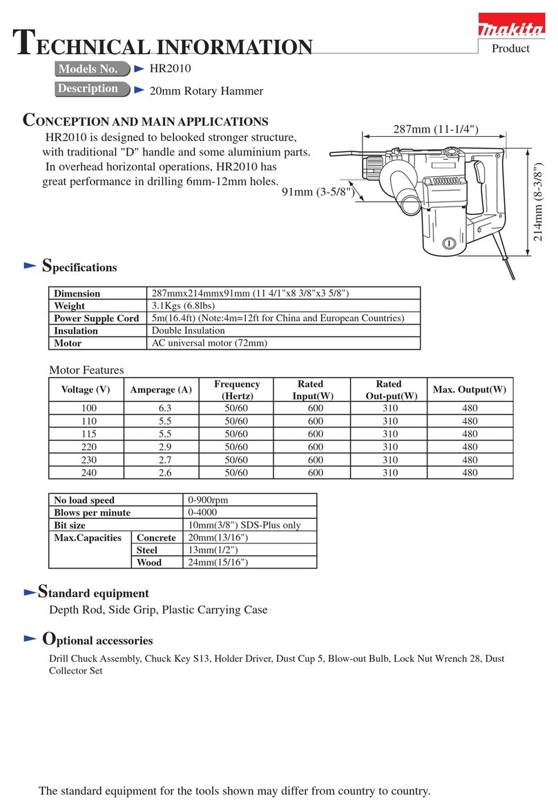
CONCEPT AND MAIN APPLICATIONS
Specification
Dimensions: mm (")
Width (W)
Height (H)
Length (L) 479 (18-11/16)
HR4013C
112 (4-3/8)
HR4003C
106 (4-3/16)
263 (10-3/8)
HR4013C, HR4003C
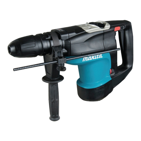
40mm (1-9/16") Rotary Hammer
Model HR4013C/HR4003C are the successor models of the current
HR4011C series models and developed to provide higher operating
efficiency and more comfort with unrivalled low level of vibration,
the optional dust extractor attachment newly designed, etc.
Listed below are the specification differences between
HR4013C and HR4003C.
Standard equipment
Note: The standard equipment for the tool
shown above may vary by country.
Depth gauge (Stopper pole) ..........................1
Side handle assembly (D-shaped) .................1
Side handle (Bar style) ..................................1
Bit grease ......................................................1
Cleaning cloth ...............................................1
Plastic carrying case ......................................1
Optional accessories
Assorted TCT drill bits Assorted Core bits
Assorted Bull points Assorted Cold chisels
Assorted Scaling chisels Scaling chisel (for Tile)
Grooving chisel Shank (for Bushing tool and Rammer)
Bushing tool Rammer
Scoop Side handle assembly (D-shaped)
Chemical anchor adaptor Bit Grease
Hammer grease Safety Goggle
Bar style side handle Plastic carrying case
Syringe Hammer Service Kit
Dust extractor attachment
W
H
L
*Anti-Vibration Technology
AVT*
Active dynamic vibration absorber
Vibration absorbing housing
Soft no load
HR4013C HR4003C
Yes
Yes
Yes
No
No
No
PRODUCT
P 1/ 19
TECHNICAL INFORMATION
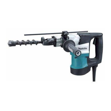
(The image above is HR4013C.)
Adapted for SDS-MAXShank type
250 - 500No load speed: min.ˉ¹ = rpm
1,450 - 2,900Impacts per minute: min.ˉ¹ = ipm
Weight according to
EPTA-Procedure 01/2003*: kg (lbs)
Europe: 4.0 (13.1), Brazil, Chile, Peru: 2.0 (6.6),
Other countries: 5.0 (16.4)
Power supply cord: m (ft)
Double insulation
6.2 (13.8)6.8 (15.1)
Protection from electric shock
YesSoft start
YesConstant speed control
NoYesSoft no load
YesTorque limiter
Capacity: mm (")
Electronic features
Concrete 105 (4-1/8)
40 (1-9/16)
YesVariable speed control switch
Core bit
TCT bit
HR4013C HR4003C
Specification Model
* With Side handle (Bar style)
240 6.2 50/60 1,100 1,500
Continuous Rating (W)
Voltage (V) Cycle (Hz) Input Output
500
Max. Output (W)
110
120
220
230
12
11
6.2
6.2
50/60
50/60
50/60
50/60
1,100
1,100
1,100
1,500
1,500
1,200
1,200
Current (A)
500---
550
550
550
[2] LUBRICATION
[1] NECESSARY REPAIRING TOOLS
Repair
DescriptionCode No. Use for
Retaining ring S pliers ST-2N1R003 removing Ring spring 25 from Tool holder
Bearing plate (for arbor press)1R022
1R027
removing Helical gear 38
Bearing setting pipe 18-10.2 assembling Torque limiter
expanding the ends of Torsion spring 7
Bearing setting plate 8.21R032 supporting Crank housing for assembling Cylinder to the inside
removing Armature from Gear housing completeGear extractor (large)1R045
assembling Crank section to Crank housing and Connecting rodRing spring setting tool B1R165
Round bar for Arbor 9-1001R238 removing Crank shaft
V block1R258 assembling Crank section to Crank housing
Tip for Retaining ring pliers1R212 Attachment of 1R003
Cylinder extractor1R213 disassembling Cylinder from Crank housing
Taper sleeve1R214 fitting Fluoride ring 25 to Impact bolt
Bearing extractor1R269 removing Ball bearings
Hammer vise1R312 supporting the machine
1R291 removing Retaining Ring S-8
Ring spring removing jig1R306 removing Crank shaft
Retaining ring S and R pliers
Spring fixing jig1R400 disassembling Cylinder from Crank housing
1R350 disassembling Cylinder from Crank housing
Ring spring removing tool1R363 removing Ring spring 25
Ring 60 (3 pcs.)

Apply the following grease to protect parts and product from unusual abrasion.
* Makita grease R No.00 to the portions indicated by black triangle
* Makita grease N No. 2 to the portions indicated by gray triangle
CAUTION: Repair the machine in accordance with “Instruction manual” or “Safety instructions”.
Fig. 1
Barrel and Tool holder section
Item No. Description Grease AmountPortion to lubricate
1
13
17
19
22
26
24
Tool holder cap
20 Tool retainer
(13a) Oil seal 32
(13b) Plane bearing 32
Barrel
complete
(13c) Plane bearing 45
Flat washer 32
Flat washer 32
Bit installation side
Crank housing side
21 Tool holder 10g
a little
a little
Inner surface where 26 Impact bolt contacts
O ring 20
Impact bolt
O ring 20
Lip portion
Portion where Bit contacts
Inner surface where 21 Tool holder contacts
Portion where 21 Tool holder contacts
Drum portion
N No.2
R No.00
17
13
(13b)
1
(13c)
(13a)
19
20
20
21
24
26
22
P 2/ 19
[2] LUBRICATION (cont.)
Item No. Description Portion to lubricate Amount
78 Crank housing complete
42 Cylinder 28.5
52
49
31
47 O ring 21 on Piston
Spiral bevel gear 26
Connecting rod
O ring 22 on Striker
95 Gear housing complete
Oil seal 15
Inside between Striker and Piston
Whole portion
Gear teeth
Hole for Crank shaft pin
Whole portion
Gear teeth of Torque limiter, Helical gear 37 and Armature
Crank room 78b
Lip portion
Inner periphery of Plane bearing 54 78a
(The component of Crank housing complete)
Fig. 2
Grease
R No.00
96
Crank housing and Motor section
20g
20g
a little
a little
10g
a little
44 O ring 30 (3 pcs.) Revealed surface from Cylinder
44
48 O ring 22 on Piston Whole portion
Fig. 3
Item No. Description Portion to lubricate Amount
Drum portion
AVT mechanism (for HR4013C only)
Counter weight
Compression spring 11
Holder complete
55
Grease
R No.00 a little
96
Armature
42
47
49
31
48
Striker
Inside view of
Cylinder
Outside view of
Cylinder
Piston
O ring 19
Spring plate
55
52
95
78
78a
78b
Crank shaft
Repair
P 3/ 19
Fig. 4
[3] DISASSEMBLY/ASSEMBLY
[3]-1. Chuck
DISASSEMBLING
1R312
Ring 28
Rubber ring 30
Chuck cover
Release cover
Chuck ring
Spring guide
Spring guide
Compression spring 46
Tool
retainer
1. Set the machine to 1R312 or the like,
and remove Tool holder cap by prying
off with a slotted screwdriver.
2. Insert the dummy shank of 1R363 into Tool holder,
and lock it same way as you do for a real bit.
Press down Ring 28 under Ring spring 25 by turning
M8 Nut of 1R363 clockwise using a socket wrench 13,
and remove Ring spring 25 using 1R003 and 1R212.
3. Remove Ring 28, Chuck cover, Rubber ring 30,
Chuck ring and Release cover from Tool holder.
4. Remove a pair of Tool retainer by pressing down
Spring guide. Then separate Spring guides and
Compression spring 46 from Tool holder.
Dummy shank of
SDS-MAX bit
Tool holder cap
Chuck section can be disassembled as drawn in Fig. 4.
Tool holder cap
Repair
P 4/ 19
ASSEMBLING
Assemble Chuck section by reversing the disassembly procedure.
Refer to Fig. 4.
Note: It is difficult to set Tool holder cap in place by hand.
Put Tool holder cap on floor, and push Tool holder of
the machine to the cap while making use of the machine
weight.
Fig. 5
Ring 28
Ring spring 25
1R363
Socket wrench 13
1R003
1R212
[3] DISASSEMBLY/ASSEMBLY
[3]-2. Impact bolt, Striker
DISASSEMBLING
1. Remove Housing cap by levering it up with
a slotted screwdriver. And then, remove four
M6x30 Hex socket head bolts.
Housing cap
(1) Impact bolt, Striker Piston can be disassembled without removing Chuck section. See Fig. 6.
(2) Striker is removed from Crank housing side as drawn in Fig. 7.
Impact bolt
Long bar
M6x30 Hex socket head bolt (4 pcs.)
2. Remove Barrel section and Housing cover complete
together from Crank housing complete by grabbing
and lifting up the chuck by hand.
Fluoride ring 25
(the worn one)
3. Insert a long bar into Chuck and then push out Impact bolt.
Note: All the Rings on Impact bolt have to be replaced
when O ring 20 (orange) shows through the worn
Fluoride ring 25.
O ring 20
(orange)
Repair
P 5/ 19
Fig. 6
Fig. 7
1. Remove the parts from the Crank housing side. 2. Remove Striker by tapping Cylinder
carefully with a plastic hammer
Note: Replace old/ worn O ring 22 with a new one.
Cylinder
Striker
Ring 17
Rubber ring 18
Slide sleeve
Crank housing
Compression spring 33
O ring 22
[3] DISASSEMBLY/ASSEMBLY
[3]-2. Impact bolt, Striker (cont.)
ASSEMBLING
Fig. 8
(1) Assemble O rings and Fluoride rings to Impact bolt as drawn in Fig. 8.
1R214
Assembly of Rings to Impact Bolt
Correction
Insert Impact bolt from
the HR4000C side of
1R214. And keep
Impact bolt approx.
60 seconds in 1R214.
Impact bolt
Wrong
Correct
Before Correction:
Rings' edges are protruding from
the top edge of the groove on
Impact bolt.
groove on Impact bolt
Be careful about the assembly direction
of Impact bolt when inserting it into
Tool holder.
Fluoride ring 25
O ring 20O ring 20
After Correction:
Rings' edges are positioned under
the top edge of the groove on
Impact bolt.
Corrected
Repair
P 6/ 19
Fig. 9
2. Assemble the parts drawn below to Cylinder. Be careful
about the assembly directions of Ring 17 and Slide sleeve.
1. Insert Striker into Cylinder so that
the O ring 22 side faces to Piston
in Crank housing.
(2) Assemble Striker section as drawn in Fig. 9.
(3) Assemble Barrel section to Cylinder. Refer to Fig. 6.
Cylinder
Ring 17
Correct Wrong
Rubber ring 18
Slide
sleeve
Compression spring 33
O ring 22
Striker Cylinder
1R312
P 7/ 19
DISASSEMBLING
Fig. 10
Fig. 11
(1) After removing Barrel section as drawn in Fig. 6, disassemble Handle section as drawn in Fig. 10.
(2) Remove six M4x16 Pan head screws and Crank cap.
While expanding the ends of Torsion spring 7 with 1R003, remove Flat fillister head pin 6 on Link plate. (Fig. 11)
As for HR4003C,
• the removal precess of Guard 40 can be skipped.
• Disassemble Handle section by unscrewing six 4x25 Tapping screws.
1. Reserve the insertion slit for a slotted screwdriver between Guard 40
and Handle base for HR4013C by pressing Handle section toward
Crank housing side.
And remove Guard 40 by prying it up with a slotted screwdriver.
2. Disassemble Handle section for
HR4013C by unscrewing eight
4x25 Tapping screws.
Guard 40
Slotted screwdriver
[3] DISASSEMBLY/ASSEMBLY
[3]-3. Crank housing, Cylinder, Counter weight
Repair
4x25 Tapping screw
(8 pcs.)
Torsion spring 7
1R003
Flat fillister head pin 6Link plate
M4x16 Pan head screw (6 pcs.)
Crank cap
[3] DISASSEMBLY/ASSEMBLY
[3]-3. Crank housing, Cylinder, Counter weight
(3) Remove Drive sleeve by pushing the end of Link plate from Crank side. Then, remove Guide ring. (Fig. 12)
(4) Put three pieces of 1R350 on Crank housing complete, and then remove Cylinder from Crank housing with 1R213
through the holes of the three pieces of 1R350. (Fig. 13)
(5) Remove Spiral bevel gear 26 from Crank housing carefully so as not to be tilted. (Fig. 14)
When Spiral bevel gear 26 is tilted in Crank housing in the disassembly process;
- it is impossible to remove Spiral bevel gear 26.
- Plane bearing 54 in Crank housing is harmed.
Fig. 13 Fig. 14
Fig. 12
Repair
P 8/ 19
Guide ring
Link plate
Driving sleeve
1R350
(3 pcs.)
1R213
Crank housing
complete
Spiral bevel gear 26
Plane bearing 54
(The component of Crank housing)
Cylinder
Insert the two pins of 1R213 into the holes of Cylinder,
and then turn the handle of 1R213
(6) Put 1R400 on Flat washer 33 located on Chuck side of Cylinder. Assemble two pieces of 1R022 to 1R306.
Set 1R306 to Arbor press.
Then compress Compression spring 34 by pressing down 1R400 using Arbor press with 1R022 and 1R306 until
Retaining ring (EXT) WR-32.5 is revealed, and remove it with 1R003 with 1R212. (Fig. 15)
(7) Return Compression spring 34 back to the original shape gradually by reducing the pressure.
Cylinder section is disassembled as drawn in Fig. 16.
[3] DISASSEMBLY/ASSEMBLY
[3]-3. Crank housing, Cylinder, Counter weight (cont.)
Repair
P 9/ 19
Fig. 15
Fig. 16
Flat washer 33
Compression spring 34
Retaining ring (EXT)
WR-32.5
Flat washer 33
Retaining ring EXT WR-32.5Cylinder 28.5
1R400
1R022
1R306
Arbor press
Retaining ring (EXT)
WR-32.5
Ring 33 O ring 30 (3 pcs.)
Chuck side Crank housing
side
Retaining ring (EXT)
WR-32.5 1R003 with 1R212
Note: Set two 1R022 to 1R306 while keeping the same
spaces between two 1R022 and Cylinder.
Otherwise, it will be extremely difficult to expand
Retaining ring (EXT) WR-32.5 due to the tight space.
Repair
P 10/ 19
(8) As for model HR4013C, loosen four M4x16 Pan head screws and remove Switch case set from Crank housing. (Fig. 17)
Then, Push and Turn each Holder complete on both sides of Crank housing with a slotted screwdriver to
remove counter weight mechanism. (Fig. 18)
(9) Loosen four 5x25 Tapping screws and then remove Crank housing and Gear housing from Motor housing. (Fig. 19)
(10) Move the pin portion of Crank shaft to the closest position to Handle side. (Fig. 20)
Put two pieces of 1R238 on Crank shaft as drawn in Fig. 21, then hold 1R238 to 1R306 on Arbor press.
Press down Crank shaft together with Ball bearing 6004LLU,Retaining ring S-20 and Helical gear 10. (Fig. 21)
(11) Connecting rod with Piston section can be removed from Cylinder side. Disassemble Piston section. (Fig. 22)
[3] DISASSEMBLY/ASSEMBLY
[3]-3. Crank housing, Cylinder, Counter weight (cont.)
Fig. 17
Fig. 19
Fig. 21 Fig. 22
Fig. 20
Fig. 18
Switch case set
Compression spring 11Spring plate
Push and Turn
Holder
counterclockwise
on the left .
Push and turn Holder clockwise
on the right.
Counter weight
Holder complete
Counter weight mechanism
Crank housing complete
Handle installation side
Note:
If the position is moved from
the closest, the pin portion will
be hooked with Crank housing
Cylinder side
M4x16 Pan
head screw
(4 pcs.)
5x25 Tapping screw (4 pcs.)
Handle installation side
Crank shaft
1R238
(2 pcs.)
1R306 Pin 7 Piston
O ring 21
O-ring 22
Connecting
rod
Arbor press
Cylinder side
28mm
Crank housing
Crank shaft
Crank section
Ball bearing 6004LLU
Retaining ring S-20
Helical gear 37
1R306
Arbor press
Arbor press table
Repair
P 11/ 19
Assemble the components by reversing the disassembly procedure.
(1) Put Piston section into Crank housing.
(2) Insert Crank section (drawn in Fig. 21) straight into the hole of Crank housing by hand so that the outer periphery of
Ball bearing 6004LLU is slightly held in the hole of Crank housing.
(3) Move the pin of Crank shaft to the closest position to Handle installation side (Fig. 20), and turn Crank housing
upside down and put on 1R258 with care not to move the pin position. (Fig. 23)
(4) Pressfit Ball bearing 6004LLU in place with 1R165 carefully so as not to cause misalignment between the pin of
Crank shaft and the hole of Connecting rod. (Fig. 24)
(5) Turn Crank housing upside down and put 1R165 between Arbor press table and Ball bearing 6004LLU, then fit
the pin of Crank shaft into the hole of Connecting rod using 1R306 and Arbor press. (Fig. 25)
(6) Once Oil seal 32 in Barrel complete is removed, using Socket bit 32-50 (Makita part No. 134848-9) makes it easy to
pressfit Oil seal 32 in place.
[3] DISASSEMBLY/ASSEMBLY
[3]-3. Crank housing, Cylinder, Counter weight (cont.)
Fig. 25
Fig. 24Fig. 23
ASSEMBLING
1R258 1R258
1R165
Arbor press
View from
Handle side
Pin of
Crank shaft
Crank housing
Crank housing
1R165
1R306
View from Handle side
Crank housing
1R165
Pin of
Crank shaft
Ball bearing
6004LLU
Inside view of Crank housing
Arbor press table
Connecting rod
Arbor press
1R032
Crank housing
Two pins
Four pins
Two pins
Repair
P 12/ 19
(7) When Seal ring 8 is removed from Crank housing, be sure to fit Seal ring 8 into the groove of Crank housing before
setting Link plate in place.
Fit Seal ling 8 into the groove of Crank housing especially around Link plate, and pass Link plate through the slot in
Seal ring 8 from the opposite in advance to make space for the smooth installation of Link plate. Their ways will make
it easy to set Link plate in place later. (Fig. 26)
(8) Spiral bevel gear 26 must be installed straight. (Fig. 27) Do not fail to apply Makita grease No. R 00 to the gear teeth.
(9) Three pieces of O ring 30 on Cylinder must be lubricated with Makita grease No. R 00. (Fig. 2 of [2] LUBRICATION)
When Cylinder is pressfit into Crank housing, Put 1R032 under the four pins on handle side of Crank housing as drawn
in Fig. 28. Place Guide ring in Crank housing as drawn in Fig. 29. Be careful about the direction of Guide ring.
Insert the hooks of Link plate into the center groove of Driving sleeve, and install them into Crank housing. (Fig. 30)
At this time;
• engage the gear teeth of Spiral bevel gear 26 and the cam groove of Driving sleeve.
• pass Link plate through the slot of Seal ring 8.
[3] DISASSEMBLY/ASSEMBLY
[3]-3. Crank housing, Cylinder, Counter weight (cont.)
Fig. 28
Fig. 26 Fig. 27
Fig. 30
Fig. 29
Link plate
Slot of Seal ring 8
Apply Makita grease No. R 00 to
the gear teeth of Spiral bevel gear 26.
Wide notch of
Guide ring
Cylinder section
Four pins
Center groove of
Driving sleeve
Hooks of Link plate
Repair
P 13/ 19
(10) When Change lever section is disassembled;
• fit the projection of Leaf spring into the groove on Link lever. (Fig. 31)
• reassemble the components to Crank cap and Housing cover by M4x10 Pan head screw with care to the directions
(Fig. 31)
• assemble Crank cap to Crank housing while aligning the pin of Crank cap to the opening of Link guide (Fig. 32).
(11) In the process of reassembling, i.e., as drawn in Fig. 33, set Change lever section in place temporarily and turn
Change lever counterclockwise and clockwise to check that Driving sleeve moves back and forth.
(12) When Switch case set and Control plate are set in place;
• while facing the mark of “>POM-xxxx<” on Control plate to the upper side, pass the projection of Crank lever
through the rounded opening of Control plate.
• pass the square pin of Switch lever C through the long opening of Control plate.
Crank lever
O ring 18
Projection of Leaf spring
Groove of Link lever
M4x10 Pan head screw
Driving sleeve
Long opening
of Control plate
Change lever
Crank cap
[3] DISASSEMBLY/ASSEMBLY
[3]-3. Crank housing, Cylinder, Counter weight (cont.)
Fig. 31
Fig. 32 Fig. 33
Fig. 34
Projection of Crank lever
Mark on
Crank cap
Projection of
Crank lever
Rounded opening
of Control plate
Switch case set
Pin of Link lever
Pin of Link lever
Opening of Link
guide
Mark on the reverse
side of Crank cap
Square pin of
Switch lever C
Repair
P 14/ 19
(1) Remove Gear housing from Crank housing according to [3]-3 of the previous pages.
(2) Tap Gear housing as drawn in Fig. 35 with a plastic hammer. Torque limiter assembly is removed.
(3) Remove Retaining spring S-8 from the shaft of Spiral bevel gear 7 with 1R291. After removing Flat washer 8, separate
Ball bearing 608DDW with 1R269. (Fig. 36) Shoulder washer 8 is removed.
(4) Use two 1R258 to receive guide plate portion of Torque limiter complete, press down the shaft of Spiral bevel gear 7.
(Fig. 37)
Spiral bevel gear 7, Key 4 (2 pcs.), Ball bearing 6002LLU and Torque limiter complete are removed. (Fig. 38)
Note: Do not disassemble Torque limiter complete. Once it is disassembled, it is impossible reassemble them again.
Gear housing
Plastic hammer
Torque limiter assembly Retaining ring S-8
Ball bearing 608DDW
Ball bearing 6002LLU
[3] DISASSEMBLY/ASSEMBLY
[3]-4. Torque limiter assembly
Fig. 35 Fig. 36
Fig. 37 Fig. 38
Fig. 39
Shoulder washer 8
Torque limiter
complete
Flat washer 8
Spiral bevel gear 7 with two keys 4
Assemble by reversing the disassembly procedure.
When Shoulder washer 8 is pressfit to Spiral bevel gear 7 in Torque limiter
complete, place 1R027 to the round center portion of Shoulder washer 8 to
press it down. (Fig. 39)
Spiral bevel gear 7
Round center portion
of Shoulder washer 8
Torque limiter complete
Ball bearing 6002LLU
Key 4 (2 pcs.)
1R027
Arbor press
DISASSEMBLING
ASSEMBLING
1R258
Receive guide plate portion
of Torque limiter complete
with two 1R258.
Shaft of Spiral bevel gear 7
Repair
P 15/ 19
(1) Do the steps until four 5x25 Tapping screws are removed according to [3]-3-(9) of the previous pages. (Fig. 19)
(2) Loosen two 4x18 Tapping screws and then remove Rear cover. (Fig. 40)
(3) While holding Fan by a gloved hand, turn M6 Hex nut counterclockwise using Cordless impact driver with Socket bit
10.(Fig. 41)
(4) Because Carbon brushes are pressed with Spiral springs to maintain their contacts with Armature's commutator.
Slide and detach the spiral springs from Carbon brushes and put them aside. Check that Carbon brushes are detached
from Commutator of Armature. (Fig. 42)
(5) Tap Armature shaft and then pull Crank housing and Gear housing to remove them from Motor housing. (Fig. 43)
Armature is removed together with Gear housing. (Fig. 44)
(6) Remove Armature from Gear housing with 1R045. (Fig. 45)
[3] DISASSEMBLY/ASSEMBLY
[3]-5. Motor
Fig. 40 Fig. 41 Fig. 42
Fig. 43 Fig. 44
Fig. 45
Assemble by reversing the disassembly procedure.
4x18 Tapping screw (2 pcs.)
Rear cover
DISASSEMBLING
ASSEMBLING
Cordless impact driver with Socket bit 10 Spiral spring Carbon brush
M6 Hex nut
Crank housing
Gear housing
Crank housing Armature shaft
1R045
Repair
P 16/ 19
Loosen 4x18 Tapping screw and then
lever up Handle cover with a slotted
screwdriver. (Fig. 46)
Main switch can be replaced. (Fig. 47)
[3] DISASSEMBLY/ASSEMBLY
[3]-6. Handle section Fig. 46 Fig. 47
DISASSEMBLING
4x18
Tapping screw
Slotted screwdriver
Handle cover Main switch
[3]-7. Fastening Torque
Fasten the bolts to the fastening torque listed in Fig. 48.
Item No. Fastening torqueQ'tyDescription
47.8 - 12.0 N∙mM6x30 Hex socket head bolt
M5x25 Tapping screw
75
12
114 1
1
1.8 - 3.7 N∙m
3.0 - 3.5 N∙m
M6 Hex nut
Fig. 49
114 M6 Hex nut
12 M6x30 Hex socket
head bolt (4 pcs.)
75 M2x25 Tapping
screw (4 pcs.)
Gear housing complete
Barrel complete
[4] Maintenance
When replacing Carbon brushes, it is recommended to do replace the following parts (Fig. 49) and apply appropriate
amount of lubricants (Figs. 1 to 3) at the same time for longer service life of the machine.
1 Tool holder cap
22 O ring 20
23 Fluoride ring 25 on Impact bolt
24 O ring 20
31 O ring 22 on Striker
48 O ring 22 on Piston
Fig. 48
Fan 76 (Armature Fan)
Motor housing
Crank housing complete
(Ring 17)
(Rubber ring 18)
(Slide sleeve)
(Impact bolt) (Striker) (Piston)
31 48
23 Fluoride ring 25
22 23 24 251
Color index of lead wires' sheath
Black
Connector
Connector
Power supply cord
White
Red
Fig. D-1
Controller
Terminal block
with Line filters
Circuit diagram
Blue
Switch
Dial
Brown lead wire is used
for some countries.
Blue lead wire is used
for some countries.
Switch unit
P 17/ 19
Wiring diagram
Fig. D-2
Switch unit
Boss
Rib BRib A
Rib D
Rib C
[Handle section] [Switch unit]
Fix the Lead wires
of Lead unit with
Lead wire holder.
Route one Lead wire
between Rib A and Boss,
the other between Rib B
and Boss.
Route Lead wires of Switch unit
between Ribs C and D.
Route Lead wires
of Switch unit
in this groove.
Pass Lead wires through
the opening of Handle.
P 18/ 19
Wiring diagram
Fig. D-3
[Motor housing]
Dial
Rib FRib E
Controller
Connector
Fix Lead wires connected to Connector in
each Lead wire holder.
Note: Do not put Lead wires on or over Ribs
and the inner wall of Motor housing.
Do not put Lead wires on or over
the inner wall of Motor housing.
Route Lead wires of Switch unit
between Ribs E and F.
P 19/ 19

Other manuals for HR4013C

1

This manual suits for next models

1

Other Makita Rotary Hammer manuals

Makita HR3200C User manual

Makita

Makita HR3200C User manual

Makita HR2450X8 User manual

Makita

Makita HR2450X8 User manual

Makita HR009G User manual

Makita

Makita HR009G User manual

Makita HR1820 User manual

Makita

Makita HR1820 User manual

Makita DHR165Z User manual

Makita

Makita DHR165Z User manual

Makita HR2450 Series User manual

Makita

Makita HR2450 Series User manual

Makita HR2800 User manual

Makita

Makita HR2800 User manual

Makita BHR240 User manual

Makita

Makita BHR240 User manual

Makita HR2450 Series User manual

Makita

Makita HR2450 Series User manual

Makita HR2230 User manual

Makita

Makita HR2230 User manual

Makita HR4003C User manual

Makita

Makita HR4003C User manual

Makita HR4500C User manual

Makita

Makita HR4500C User manual

Makita HR4501C User manual

Makita

Makita HR4501C User manual

Makita HR2800 User manual

Makita

Makita HR2800 User manual

Makita HR5000K User manual

Makita

Makita HR5000K User manual

Makita HR166D User manual

Makita

Makita HR166D User manual

Makita HR4003C User manual

Makita

Makita HR4003C User manual

Makita HR5210C User manual

Makita

Makita HR5210C User manual

Makita HR4501C User manual

Makita

Makita HR4501C User manual

Makita HR2300 Manual

Makita

Makita HR2300 Manual

Makita HR2230 User manual

Makita

Makita HR2230 User manual

Makita Rotary Hammer User manual

Makita

Makita Rotary Hammer User manual

Makita HR4501C User manual

Makita

Makita HR4501C User manual

Makita HR2445 User manual

Makita

Makita HR2445 User manual

Popular Rotary Hammer manuals by other brands

Hitachi DH24PB3 Technical data and service manual

Hitachi

Hitachi DH24PB3 Technical data and service manual

HIKOKI DH 28PD Handling instructions

HIKOKI

HIKOKI DH 28PD Handling instructions

KRESS KUC60 Original instructions

KRESS

KRESS KUC60 Original instructions

DeWalt SDS plus DCH072 instruction manual

DeWalt

DeWalt SDS plus DCH072 instruction manual

DeWalt D25481 manual

DeWalt

DeWalt D25481 manual

Worx Professional WU334 Safety and operating manual original instructions

Worx Professional

Worx Professional WU334 Safety and operating manual original instructions

Worx WX390 Original instructions

Worx

Worx WX390 Original instructions

Hilti TE 70-AVR Original operating instructions

Hilti

Hilti TE 70-AVR Original operating instructions

Hilti NURON TE 50-22 Original operating instructions

Hilti

Hilti NURON TE 50-22 Original operating instructions

Hitachi DH 38YE2 Safety instructions and instruction manual

Hitachi

Hitachi DH 38YE2 Safety instructions and instruction manual

Bosch 0611914003 instructions

Bosch

Bosch 0611914003 instructions

Casals CCH32VCEK Original instructions

Casals

Casals CCH32VCEK Original instructions

Siefken SCHOCK DAMON SD4210 instructions

Siefken

Siefken SCHOCK DAMON SD4210 instructions

Bosch 11245EVS - 2" SDS-Max Combination Hammer parts list

Bosch

Bosch 11245EVS - 2" SDS-Max Combination Hammer parts list

YATO YT-09904 manual

YATO

YATO YT-09904 manual

AEG BBH18C-0 Original instructions

AEG

AEG BBH18C-0 Original instructions

Hitachi DH 50MRY parts list

Hitachi

Hitachi DH 50MRY parts list

Bosch GBH 2-23 S Professional Original instructions

Bosch

Bosch GBH 2-23 S Professional Original instructions

manuals.online logo
manuals.online logoBrands
  • About & Mission
  • Contact us
  • Privacy Policy
  • Terms and Conditions

Copyright 2025 Manuals.Online. All Rights Reserved.