Makita BO6030 User manual

GB
Random Orbit Sander Instruction Manual
F
Ponceuse orbitale à disque Manuel d’instructions
D
Exzenterschleifer Betriebsanleitung
I
Levigatrice rotorbitale Istruzioni per l’uso
NL
Excenter schuurmachine Gebruiksaanwijzing
E
Lijadora orbital Manual de instrucciones
P
Lixadeira rotorbital Manual de instruções
DK
Excentersliber Brugsanvisning
S
Excenterslipmaskin Bruksanvisning
N
Eksentersliper Bruksanvisning
SF
Epäkeskohiomakone Käyttöohje
GR Λειαvτής τυχαίας τροχιάς Οδηγίες χρήσεως
BO6030

2
1
2
3
3
4
2
5
3
4
8
67
2
1
9
10
12
11
12
34
56
78

3
16
13
15 14
20
21
22
17
18
19
23
24 25
910
11 12
13 14
15 16

4
ENGLISH
Explanation of general view
1 Abrasive disc
2 Dust bag
3 Dust nozzle
4 Push button
5Hook
6 Groove
7 Front fixing cardboard
8 Front side of paper dust bag
9 Claws
10 Upper part
11 Notch
12 Guide
13 Screwdriver
14 Front grip
15 Hole in front grip
16 Notches
17 Screw
18 Pad
19 Hex wrench
20 Speed adjusting dial
21 Lock button
22 Switch trigger
23 Sponge pad
24 Felt pad
25 Wool pad
SPECIFICATIONS
Model BO6030
Pad diameter ...................................................... 150 mm
Abrasive disc diameter ....................................... 150 mm
Orbits per minute ..................................... 4,000 – 10,000
Sanding stroke rate ................................. 8,000 – 20,000
Overall length ..................................................... 309 mm
Net weight ............................................................. 2.3 kg
• Due to our continuing program of research and devel-
opment, the specifications herein are subject to change
without notice.
• Note: Specifications may differ from country to country.
Power supply
The tool should be connected only to a power supply of
the same voltage as indicated on the nameplate, and can
only be operated on single-phase AC supply. They are
double-insulated in accordance with European Standard
and can, therefore, also be used from sockets without
earth wire.
Safety hints
For your own safety, please refer to the enclosed safety
instructions.
SPECIFIC SAFETY RULES
GEB021-1
DO NOT let comfort or familiarity with product
(gained from repeated use) replace strict adherence
to sander safety rules. If you use this tool unsafely or
incorrectly, you can suffer serious personal injury.
1. Hold power tools by insulated gripping surfaces
when performing an operation where the cutting
tool may contact hidden wiring or its own cord.
Contact with a "live" wire will make exposed metal
parts of the tool "live" and shock the operator.
2. Always use safety glasses or goggles. Ordinary
eye or sun glasses are NOT safety glasses.
3. Hold the tool firmly.
4. Do not leave the tool running. Operate the tool
only when hand-held.
5. This tool has not been waterproofed, so do not
use water on the workpiece surface.
6. Ventilate your work area adequately when you
perform sanding operations.
7. Some material contains chemicals which may be
toxic. Take caution to prevent working dust inha-
lation and skin contact. Follow material supplier
safety data.
8. Use of this tool to sand some products, paints
and wood could expose user to dust containing
hazardous substances. Use appropriate respira-
tory protection.
9. Be sure that there are no cracks or breakage on
the pad before use. Cracks or breakage may
cause a personal injury.
SAVE THESE INSTRUCTIONS.
WARNING:
MISUSE or failure to follow the safety rules stated in
this instruction manual may cause serious personal
injury.
OPERATING INSTRUCTIONS
Installing or removing abrasive disc (Fig. 1)
Important:
• Always be sure that the tool is switched off and
unplugged before installing or removing the abrasive
disc.
• Always use hook-and-loop system abrasive discs.
Never use pressure-sensitive abrasive discs.
To install the abrasive disc, first remove all dirt or foreign
matter from the pad. Then attach the abrasive disc to the
pad, using the hook-and-loop system of the abrasive disc
and the pad. Be careful to align the holes in the abrasive
disc with those in the pad.
To remove the disc from the pad, just pull up from its
edge.
Installing dust bag (Fig. 2)
Install the dust bag on the tool so that the arrow with “UP”
indicated on the dust nozzle points upward.
Emptying dust bag
When the dust bag is about half full, switch off and
unplug the tool. Hold the tool as shown in Fig. 3 and
remove the dust bag from the dust nozzle while pressing
the push button as shown in Fig. 4. (Fig. 3 & 4)
After emptying the dust bag, insert the hook on the dust
nozzle into the rectangular hole on one side of the dust
bag frame and push up the dust bag frame until it clicks
into place on the push button (Fig. 5)

5
Installing paper dust bag
To install the paper dust bag, place the paper dust bag on
the paper dust bag holder with its front side upward.
Insert the front fixing cardboard of the paper dust bag
into the groove of the paper dust bag holder. (Fig. 6)
Then press the upper part of the front fixing cardboard in
arrow direction to hook it onto the claws. (Fig. 7)
Insert the notch of the paper dust bag into the guide of
the paper dust bag holder. Then install the paper dust
bag holder set on the tool. (Fig. 8 & 9)
Front grip (Fig. 10)
Install the front grip on the tool so that its protrusions fit
into the matching notches in the front of the tool. Secure
the front grip using a screwdriver to tighten the screw
through the hole in the front grip.
Changing pad (Fig. 11)
Makita offers an extensive range of optional super soft
and standard equipped soft pads. Remove the screw
counterclockwise from the center of the base by a sharp
tap with a hammer on the hex wrench. After changing the
pad, tighten the screw clockwise securely.
Switch action (Fig. 12)
CAUTION:
Before plugging in the tool, always check to see that the
switch trigger actuates properly and returns to the “OFF”
position when released.
To start the tool, simply pull the trigger. Release the trig-
ger to stop. For continuous operation, pull the trigger and
then push in the lock button. To stop the tool from the
locked position, pull the trigger fully, then release it.
Speed adjusting dial (Fig. 12)
The tool speed can be infinitely adjusted between
4,000 opm and 10,000 opm by turning the speed adjust-
ing dial, which is marked 1 to 5. Higher speed is obtained
when the dial is turned in the direction of number 5; lower
speed is obtained when it is turned in the direction of
number 1. Refer to the figure below for the relationship
between the number setting on the adjusting dial and the
kind of work.
A range: For polishing
B range: For finish sanding
C range: For regular sanding
NOTE:
The above figure shows standard applications. They may
differ under certain conditions.
Sanding operation (Fig. 13)
CAUTION:
• Never switch on the tool when it is in contact with the
workpiece surface, causing an injury to operator.
• Never run the tool without the abrasive disc. You may
seriously damage the pad.
• Never force the tool. Excessive pressure may decrease
the sanding efficiency, damage the abrasive disc or
shorten tool life.
Turn the tool on and wait until it attains full speed. Then
gently place the tool on the workpiece surface. Keep the
base flush with the workpiece and apply slight pressure
on the tool.
Polishing operation
CAUTION:
• Use only a Makita genuine sponge pad, felt pad or wool
pad (optional accessories).
• Always operate the tool at low speed to prevent work
surfaces from damage/burning.
• Never force the tool. Excessive pressure may decrease
the polishing efficiency and cause motor overload,
resulting in tool malfunction.
1. Applying wax (Fig. 14)
Use an optional sponge pad. Apply wax to the
sponge pad or work surface. Run the tool to smooth
out wax.
NOTE:
First, wax a non critical portion of the work surface to
make sure that the tool will not scratch the surface or
result in uneven waxing.
2. Removing wax (Fig. 15)
Use an optional felt pad. Run the tool to remove
wax.
3. Polishing (Fig. 16)
Use an optional wool pad. Run the tool and apply
the wool pad gently to the work surface.
Orbits per minute
A range
B range
C range
Dial setting

6
MAINTENANCE
CAUTION:
Always be sure that the tool is switched off and
unplugged before carrying out any work on the tool.
To maintain product safety and reliability, repairs, mainte-
nance or adjustment should be carried out by a Makita
Authorized Service Center.
ACCESSORIES
CAUTION:
These accessories or attachments are recommended for
use with your Makita tool specified in this manual. The
use of any other accessories or attachments might
present a risk of injury to persons. Only use accessory or
attachment for its stated purpose.
If you need any assistance for more details regarding
these accessories, ask your local Makita service center.
• Hook-and-loop system abrasive disc
(with pre-punched holes)
• Hook-and-loop system sponge pad
• Hook-and-loop system felt pad
• Hook-and-loop system wool pad
• Pad 150 (Super soft, Soft)
• Sanding cloth 150 – #100, #200, #800 for fine sanding
• Hex wrench 5
• Paper dust bag
• Paper dust bag holder
Grit 40 60 80 120 180 240 400
Use Coarse Medium Fine

16
NEDERLANDS
Verklaring van algemene gegevens
1 Schuurschijf
2 Stofzak
3 Stofuitlaat
4 Drukknop
5Haak
6Groef
7 Bevestigingskarton
8 Bovenzijde van papieren stof-
zak
9 Klauwen
10 Bovenste gedeelte
11 Insnijding
12 Geleider
13 Schroevendraaier
14 Voorhandgreep
15 Gat in voorhandgreep
16 Inkepingen
17 Schroef
18 Steunschijf
19 Zeskantsleutel
20 Snelheidsregelknop
21 Vergrendelknop
22 Trekschakelaar
23 Schuimrubber polijstschijf
24 Vilten polijstschijf
25 Wollen polijstschijf
TECHNISCHE GEGEVENS
Model BO6030
Diameter steunschijf ........................................... 150 mm
Diameter schuurschijf ......................................... 150 mm
Omwentelingen per minuut ..................... 4 000 – 10 000
Slagsnelheid voor schuren ...................... 8 000 – 20 000
Totale lengte ....................................................... 309 mm
Netto gewicht ......................................................... 2,3 kg
• In verband met ononderbroken research en ontwikke-
ling behouden wij ons het recht voor bovenstaande
technische gegevens te wijzigen zonder voorafgaande
kennisgeving.
• Opmerking: De technische gegevens kunnen van land
tot land verschillen.
Stroomvoorziening
Het gereedschap mag alleen worden aangesloten op
een stroombron van hetzelfde voltage als aangegeven op
de naamplaat, en kan alleen op enkel-fase wisselstroom
worden gebruikt. Het gereedschap is dubbel-geïsoleerd
volgens de Europese standaard en kan derhalve ook op
een niet-geaard stopkontakt worden aangesloten.
Veiligheidswenken
Voor uw veiligheid dient u de bijgevoegde Veiligheids-
voorschriften nauwkeurig op te volgen.
AANVULLENDE
VEILIGHEIDSVOORSCHRIFTEN
Laat u NIET misleiden door een vals gevoel van com-
fort en bekendheid met het gereedschap (na veelvul-
dig gebruik) en neem alle veiligheidsvoorschriften
van de schuurmachine altijd strikt in acht. Bij onvei-
lig of verkeerd gebruik van het elektrisch gereed-
schap, bestaat de kans op ernstig persoonlijk letsel.
1. Houd elektrisch gereedschap vast aan het geïso-
leerde oppervlak van de handgrepen wanneer u
werkt op plaatsen waar het zaaggereedschap
met verborgen bedrading of zijn eigen snoer in
aanraking kan komen. Door contact met onder
spanning staande draden, zullen de niet-geïso-
leerde metalen delen van het gereedschap onder
spanning komen te staan zodat de gebruiker een
elektrische schok kan krijgen.
2. Draag altijd een veiligheidsbril. Een gewone bril
of een zonnebril is GEEN veiligheidsbril.
3. Houd het gereedschap stevig vast.
4. Schakel het gereedschap altijd uit als u weg
moet. Schakel het gereedschap alleen in wan-
neer u het vasthoudt.
5. Dit gereedschap is niet waterdicht. Besprenkel
derhalve het oppervlak van het werkstuk niet
met water.
6. Zorg dat uw werkplaats goed geventileerd is
wanneer u gaat schuren.
7. Sommige materialen bevatten chemicaliën die
giftig kunnen zijn. Pas op dat u het werkstof van
dergelijke materialen niet inademt en vermijd
contact met de huid.Volg de veiligheidsvoor-
schriften van de leverancier van het materiaal
op.
8. Als dit gereedschap wordt gebruikt voor het
schuren van bepaalde producten, verflagen en
hout, kan de gebruiker worden blootgesteld aan
stof waarin gevaarlijke bestanddelen zitten.
Gebruik geschikte ademhalingbeschermingsap-
paratuur.
9. Controleer voor het gebruik of de schuurschijf
niet gescheurd of gebroken is. Een gescheurde
of gebroken schijf kan persoonlijk letsel vero-
orzaken.
BEWAAR DEZE VOORSCHRIFTEN.
WAARSCHUWING:
VERKEERD GEBRUIK of het niet naleven van de vei-
ligheidsvoorschriften in deze gebruiksaanwijzing
kan leiden tot ernstige verwondingen.
BEDIENINGSVOORSCHRIFTEN
Installeren of verwijderen van de schuurschijf
(Fig. 1)
Belangrijk:
• Kontroleer altijd of het gereedschap is uitgeschakeld en
de stekker van het netsnoer uit het stopkontakt is ver-
wijderd alvorens de schuurschijf te installeren of te ver-
wijderen.
• Gebruik altijd schuurschijven van het klittenband-type.
Gebruik nooit drukgevoelige schuurschijven.
Voor het installeren van de schuurschijf dient u eerst alle
vuil en stof van de steunschijf te verwijderen. Bevestig
vervolgens de schuurschijf op de steunschijf door middel
van het klittenband op de schuurschijf en steunschijf.
Zorg ervoor dat de gaten in de schuurschijf overeenko-
men met de gaten in de steunschijf.
Installeren van de stofzak (Fig. 2)
Installeer de stofzak op het gereedschap zodat het pijltje
met de “UP” indicatie op de stofuitlaat naar boven wijst.

17
Leegmaken van de stofzak
Schakel het gereedschap uit en trek de stekker uit het
stopcontact wanneer de stofzak ongeveer halfvol is.
Houd het gereedschap zoals afgebeeld in Fig. 3 en ver-
wijder de stofzak van de stofuitlaat door de drukknop in
te drukken zoals afgebeeld in Fig. 4. (Fig. 3 en 4)
Nadat de stofzak is leeggemaakt, steekt u de haak op de
stofuitlaat in het rechthoekig gat aan een van de zijden
van het stofzakfreem en dan duwt u het stofzakfreem
omhoog tot het in de drukknop vast komt te zitten.
(Fig. 5)
Installeren van de papieren stofzak
Om de papieren stofzak te installeren, plaatst u de papie-
ren stofzak met zijn bovenzijde naar boven gericht op de
stofzakhouder. Steek de onderrand van het bevestigings-
karton van de papieren stofzak in de groef van de stof-
zakhouder. (Fig. 6)
Druk daarna het bovenste gedeelte van het bevestigings-
karton in de richting van de pijltjes om het in de klauwen
vast te zetten. (Fig. 7)
Schuif de insnijding van de papieren stofzak op de gelei-
der van de stofzakhouder. Installeer daarna de stofzak-
houdermontage op het gereedschap. (Fig. 8 en 9)
Voorhandgreep (Fig. 10)
Monteer de voorhandgreep op het gereedschap door de
uitsteeksels op de voorhandgreep in de overeenkomstige
inkepingen op de voorkant van het gereedschap te pas-
sen. Zet de voorhandgreep vast door de schroef door de
opening in de voorhandgreep met een schroevendraaier
vast te draaien.
Verwisselen van de steunschijf (Fig. 11)
Makita biedt een uitgebreide keuze van los verkrijgbare
superzachte steunschijven en standaarduitgeruste
zachte steunschijven. Draai de schroef linksom los vanaf
het midden van de gereedschapsvoet door met een
hamer stevig te tikken op de zeskantsleutel. Nadat de
steunschijf is verwisseld, draait u de schroef goed vast
naar rechts.
Werking van de schakelaar (Fig. 12)
LET OP:
Alvorens de stekker van het gereedschap op een stop-
contact aan te sluiten, moet u altijd controleren of de
trekschakelaar behoorlijk werkt en bij loslaten naar de
“OFF” positie terugkeert.
Om het gereedschap te starten, drukt u gewoon de trek-
schakelaar in. Laat de trekschakelaar los om te stoppen.
Voor continuë werking, de trekschakelaar indrukken en
dan de vergrendelknop indrukken. Om het gereedschap
vanuit deze vergrendelde stand te stoppen, drukt u de
trekschakelaar volledig in en dan laat u hem los.
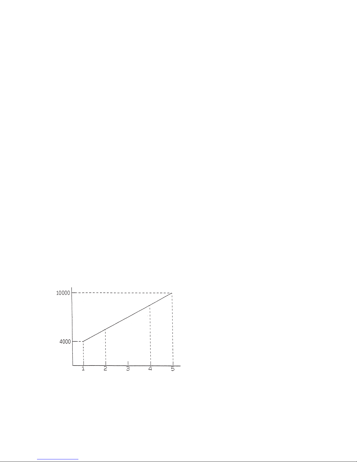
Snelheidsregelknop (Fig. 12)
Het toerental van het gereedschap kan worden afgesteld
op een willekeurig toerental tussen 4 000 rpm en
10 000 rpm. Draai hiervoor de regelknop die gemarkeerd
is van 1 tot 5. Het toerental verhoogt wanneer de regel-
knop verder naar het cijfer 5 wordt gedraaid, en verlaagt
wanneer deze terug naar het cijfer 1 wordt gedraaid. Zie
de onderstaande grafiek voor de verhouding tussen de
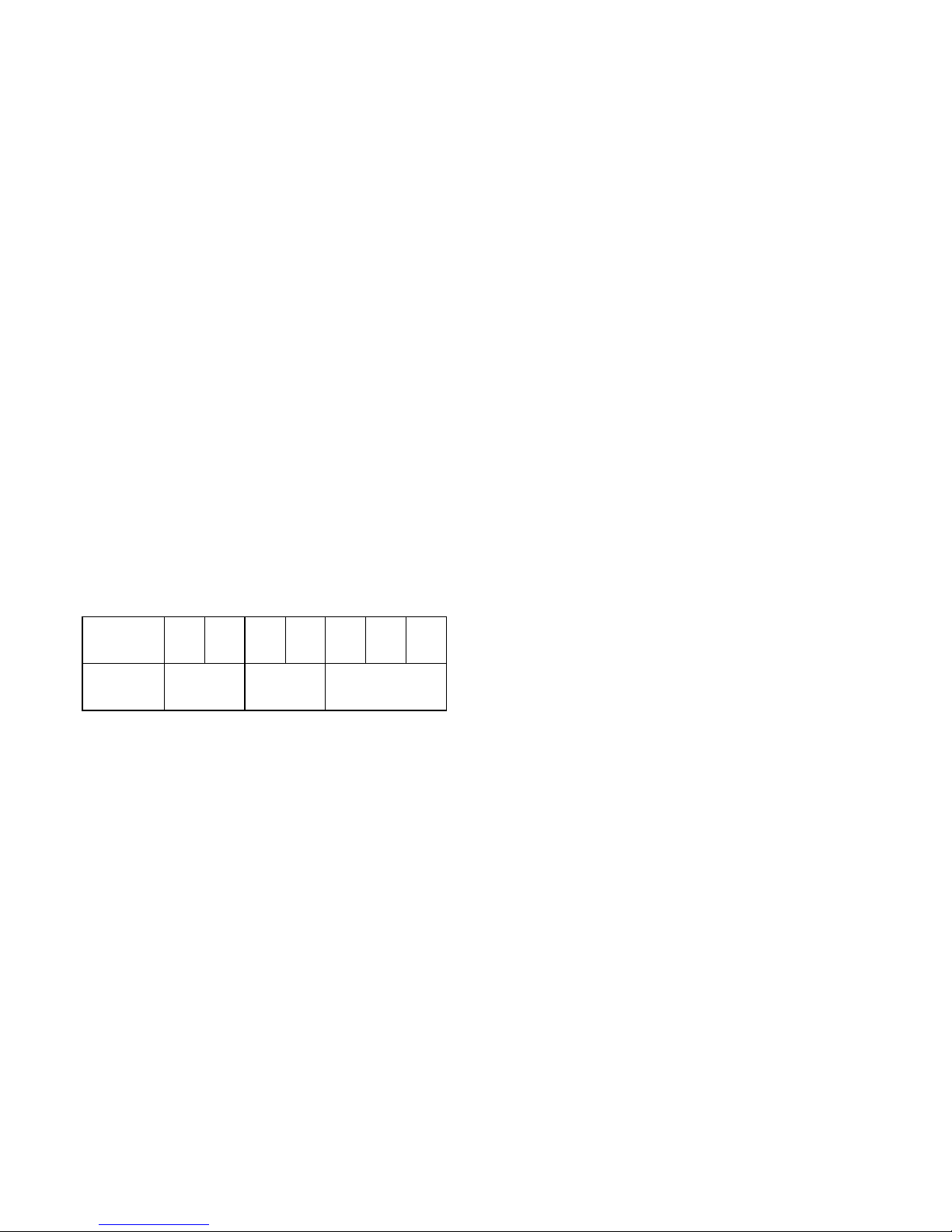
cijfers op de regelknop en het soort werk.
A bereik: Voor polijsten
B bereik: Voor afwerken (fijnschuren)
C bereik: Voor normaal schuren
OPMERKING:
De bovenstaande grafiek toont de snelheidsbereiken
voor standaard werkzaamheden. Deze kunnen echter
verschillen afhankelijk van de condities.
Schuren (Fig. 13)
LET OP:
• Schakel het gereedschap nooit in terwijl de schijf in
aanraking is met het werkstukoppervlak, aangezien de
gebruiker daardoor verwondingen kan oplopen.
• Schuur nooit met het gereedschap zonder dat de
schuurschijf is aangebracht. Als u dit doet, kan de
steunschijf ernstig beschadigd raken.
• Forceer nooit het gereedschap. Overmatige druk kan
leiden tot slechtere schuurprestaties, beschadiging van
de schuurschijf en een kortere levensduur van het
gereedschap.
Schakel het gereedschap in en wacht totdat het met volle
snelheid draait. Plaats daarna het gereedschap lang-
zaam op het werkstukoppervlak. Houd de gereedschaps-
voet vlak met het werkstuk en oefen lichte druk uit op het
gereedschap.
Polijsten
LET OP:
• Gebruik uitsluitend een originele Makita sponsrubbe-
ren, vilten of wollen schijf (los verkrijgbare accessoi-
res).
• Gebruik het gereedschap altijd bij een lage snelheid
om beschadiging/verbranding van het werkstukopper-
vlak te voorkomen.
• Forceer nooit het gereedschap. Overmatige druk kan
leiden tot slechtere polijstprestaties, overbelasting van
de motor en eventueel defect van het gereedschap.
1. Was aanbrengen (Fig. 14)
Gebruik een los verkrijgbare sponsrubberen schijf.
Breng was aan op de schijf of op het werkoppervlak.
Laat het gereedschap draaien om de was glad te
strijken.
OPMERKING:
Was eerst een onopvallend gedeelte van het werk-
stukoppervlak om er zeker van te zijn dat het
gereedschap geen krassen maakt in het oppervlak
en dat de was niet ongelijkmatig wordt uitgestreken.
Omwentelingen per minuut
Instelling van de regelknop
C bereik
B bereik
A bereik

18
2. Was verwijderen (Fig. 15)
Gebruik een los verkrijgbare vilten schijf. Laat het
gereedschap draaien om de was te verwijderen.
3. Polijsten (Fig. 16)
Gebruik een los verkrijgbare wollen schijf. Laat het
gereedschap draaien en breng de wollen schijf
zachtjes aan op het werkoppervlak.
ONDERHOUD
LET OP:
Zorg er altijd voor dat het gereedschap is uitgeschakeld
en de stekker uit het stopcontact is verwijderd alvorens
onderhoud aan het gereedschap uit te voeren.
Opdat het gereedschap veilig en betrouwbaar blijft, die-
nen alle reparaties, onderhoud of afstellingen te worden
uitgevoerd bij een erkend Makita service centrum.
ACCESSOIRES
LET OP:
• Deze accessoires of hulpstukken worden aanbevolen
voor gebruik met het Makita gereedschap dat in deze
gebruiksaanwijzing wordt beschreven. Het gebruik van
andere accessoires of hulpstukken kan gevaar voor
persoonlijke verwonding opleveren. Gebruik de acces-
soires of hulpstukken uitsluitend voor het gespecifi-
ceerde doel.
Wenst u meer informatie over deze accessoires, neem
dan contact op met het dichtstbijzijnde Makita service-
centrum.
• Klittenband-type schuurschijf
(voorzien van gaten)
• Klittenbandsysteem schuimrubber polijstschijf
• Klittenbandsysteem vilten polijstschijf
• Klittenbandsysteem wollen polijstschijf
• Steunschijf 150 (superzacht, zacht)
• Schuurdoek 150 – #100, #200, #800 voor fijnschuren
• Inbussleutel 5
• Papieren stofzak
• Papieren stofzak houder
Korrel 40 60 80 120 180 240 400
Gebruik Grof Middel Fijn

39
ENH101-5
EC-DECLARATION OF CONFORMITY
We declare under our sole responsibility that this product
is in compliance with the following standards of standard-
ized documents,
EN60745, EN55014, EN61000
in accordance with Council Directives, 89/336/EEC and
98/37/EC.
DÉCLARATION DE CONFORMITÉ CE
Nous déclarons sous notre entière responsabilité que ce
produit est conforme aux normes des documents stan-
dardisés suivants,
EN60745, EN55014, EN61000
conformément aux Directives du Conseil, 89/336/CEE et
98/37/EG.
CE-KONFORMITÄTSERKLÄRUNG
Hiermit erklärt wir unter unserer alleinigen Verantwor-
tung, daß dieses Produkt gemäß den Ratsdirektiven
89/336/EWG und 98/37/EG mit den folgenden Normen
von Normendokumenten übereinstimmen:
EN60745, EN55014, EN61000.
DICHIARAZIONE DI CONFORMITÀ
CON LE NORME DELLA COMUNITÀ EUROPEA
Dichiariamo sotto la nostra sola responsabilità che
questo prodotto è conforme agli standard di documenti
standardizzati seguenti:
EN60745, EN55014, EN61000
secondo le direttive del Consiglio 89/336/CEE e 98/37/CE.
EG-VERKLARING VAN CONFORMITEIT
Wij verklaren hierbij uitsluitend op eigen verant-
woordelijkheid dat dit produkt voldoet aan de volgende
normen van genormaliseerde documenten,
EN60745, EN55014, EN61000
in overeenstemming met de richtlijnen van de Raad
89/336/EEC en 98/37/EC.
DECLARACIÓN DE CONFORMIDAD DE LA CE
Declaramos bajo nuestra sola responsabilidad que este
producto cumple con las siguientes normas de docu-
mentos normalizados,
EN60745, EN55014, EN61000
de acuerdo con las directivas comunitarias,
89/336/EEC y 98/37/CE.
Yasuhiko Kanzaki
CE 2005
Director Amministratore
Directeur Directeur
Direktor Director
MAKITA INTERNATIONAL EUROPE LTD.
Michigan Drive, Tongwell, Milton Keynes,
Bucks MK15 8JD, ENGLAND
Responsible manufacturer: Produttore responsabile:
Fabricant responsable :Verantwoordelijke fabrikant:
Verantwortlicher Hersteller: Fabricante responsable:
Makita Corporation Anjo Aichi Japan
ENGLISH
FRANÇAISE
DEUTSCH
ITALIANO
NEDERLANDS
ESPAÑOL

40
ENH101-5
DECLARAÇÃO DE CONFORMIDADE DA CE
Declaramos sob inteira responsabilidade que este
produto obedece às seguintes normas de documentos
normalizados,
EN60745, EN55014, EN61000
de acordo com as directivas 89/336/CEE e 98/37/CE do
Conselho.
EU-DEKLARATION OM KONFORMITET
Vi erklærer hermed påeget ansvar, at dette produkt er i
overensstemmelse med de følgende standarder i de norm-
sættende dokumenter,
EN60745, EN55014, EN61000
i overensstemmelse med Rådets Direktiver 89/336/EEC
og 98/37/EC.
EG-DEKLARATION OM ÖVERENSSTÄMMELSE
Under eget ansvar deklarerar vi härmed att denna
produkt överensstämmer med följande standardiseringar
för standardiserade dokument,
EN60745, EN55014, EN61000
i enlighet med EG-direktiven 89/336/EEC och 98/37/EC.
EUs SAMSVARS-ERKLÆRING
Vi erklærer påeget ansvar at dette produktet er i over-
ensstemmelse med følgende standard i de standardis-
erte dokumenter:
EN60745, EN55014, EN61000,
i samsvar med Råds-direktivene, 89/336/EEC og 98/37/
EC.
VAKUUTUS EC-VASTAAVUUDESTA
Yksinomaisesti vastuullisina ilmoitamme, ettätämätuote
on seuraavien standardoitujen dokumenttien standar-
dien mukainen,
EN60745, EN55014, EN61000
neuvoston direktiivien 89/336/EEC ja 98/37/EC mukai-
sesti.
∆ΗΛΩΣΗ ΣΥΜΜΟΡΦΩΣΗΣ ΕΚ
∆ηλώνουµε υπ την µοναδική µας ευθύνη τι αυτ
το προιν βρίσκεται σε Συµφωνία µε τα ακλουθα
πρτυπα τυποποιηµένων εγγράφων,
EN60745, EN55014, EN61000
σύµφωνα µε τις Οδηγίες του Συµβουλίου,
89/336/EEC και 98/3 /ΚE.
Yasuhiko Kanzaki
CE 2005
Director Direktor
Direktør Johtaja
Direktör∆ιευθυντής
MAKITA INTERNATIONAL EUROPE LTD.
Michigan Drive, Tongwell, Milton Keynes,
Bucks MK15 8JD, ENGLAND
Fabricante responsável: Ansvarlig produsent:
Ansvarlig fabrikant: Vastaava valmistaja:
Ansvarig tillverkare: Υπεύθυνος κατασκευαστής:
Makita Corporation Anjo Aichi Japan
PORTUGUÊS
DANSK
SVENSKA
NORSK
SUOMI
ΕΛΛΗΝΙΚΑ

41
ENG004-2-V3
For European countries only
Noise and Vibration
The typical A-weighted sound pressure level is 75 dB (A).
Uncertainty is 3 dB (A).
The noise level under working may exceed 85 dB (A).
–Wear ear protection. –
The typical weighted root mean square acceleration
value is 4 m/s2.
These values have been obtained according to
EN60745.
Pour les pays d’Europe uniquement
Bruit et vibrations
Le niveau de pression sonore pondere type A est de
75 dB (A).
L’incertitude de mesure est de 3 dB (A).
Le niveau de bruit en fonctionnement peut dépasser
85 dB (A).
–Porter des protecteurs anti-bruit. –
L’accélération pondérée est de 4 m/s2.
Ces valeurs ont étéobtenues selon EN60745.
Nur für europäische Länder
Geräusch- und Vibrationsentwicklung
Der typische A-bewertete Schalldruckpegel beträgt
75 dB (A).
Die Abweichung beträgt 3 dB (A).
Der Lärmpegel kann während des Betriebs 85 dB (A)
überschreiten.
–Gehörschutz tragen. –
Der gewichtete Effektivwert der Beschleunigung beträgt
4m/s
2.
Diese Werte wurden gemäß EN60745 erhalten.
Modello per l’Europa soltanto
Rumore e vibrazione
Il livello di pressione sonora pesata secondo la curva A è
di 75 dB (A).
L’incertezza èdi 3 dB (A).
Il livello di rumore durante il lavoro potrebbe superare gli
85 dB (A).
–Indossare i paraorecchi. –
Il valore quadratico medio di accellerazione èdi 4 m/s2.
Questi valori sono stati ottenuti in conformitàEN60745.
Alleen voor Europese landen
Geluidsniveau en trilling
Het typische A-gewogen geluidsdrukniveau is 75 dB (A).
Onzekerheid is 3 dB (A).
Tijdens het werken kan het geluidsniveau 85 dB (A) over-
schrijden.
–Draag oorbeschermers. –
De typische gewogen effectieve versnellingswaarde is
4m/s
2.
Deze waarden werden verkregen in overeenstemming
met EN60745.
Para países europeos solamente
Ruido y vibración
El nivel de presión sonora ponderada A es de 75 dB (A).
Incerteza 3 dB (A).
El nivel de ruido en condiciones de trabajo puede que
sobrepase los 85 dB (A).
–Póngase protectores en los oídos. –
El valor ponderado de la aceleración es de 4 m/s2.
Estos valores han sido obtenidos de acuerdo con
EN60745.
ENGLISH
FRANÇAISE
DEUTSCH
ITALIANO
NEDERLANDS
ESPAÑOL

42
ENG004-2-V3
Só para países Europeus
Ruído e vibração
O nível normal de pressão sonora A é75 dB (A).
A incerteza éde 3 dB (A).
O nível de ruído durante o trabalho pode exceder
85 dB (A).
–Utilize protectores para os ouvidos –
O valor médio da aceleração é4 m/s2.
Estes valores foram obtidos de acordo com EN60745.
Kun for lande i Europa
Lyd og vibration
Det typiske A-vægtede lydtryksniveau er 75 dB (A).
Der er en usikkerhed på3 dB (A).
Støjniveauet under arbejde kan overstige 85 dB (A).
–Bær høreværn. –
Den vægtede effektive accelerationsværdi er 4 m/s2.
Disse værdier er beregnet i overensstemmelse med
EN60745.
Endast för Europa
Buller och vibration
Den typiska-A-vägda ljudtrycksnivån är 75 dB (A).
Osäkerheten är 3 dB (A).
Bullernivån under pågående arbete kan överstiga
85 dB (A).
–Använd hörselskydd –
Det typiskt vägda effektivvärdet för acceleration är
4m/s
2.
Dessa värden har erhållits i enlighet med EN60745.
Gjelder bare land i Europa
Støy og vibrasjon
Det vanlige A-verktet lydtrykksnivåer 75 dB (A).
Usikkerheten er på3 dB (A).
Under bruk kan støynivået overskride 85 dB (A).
–Benytt hørselvern. –
Den vanlig belastede effektiv-verdi for akselerasjon er
4m/s
2.
Disse verdiene er beregnet eller målt i samsvar med
EN60745.
Vain Euroopan maat
Melutaso ja tärinä
Tyypillinen A-painotettu äänenpainetaso on 75 dB (A).
Epävarmuus on 3 dB (A).
Melutaso työpaikalla saattaa ylittää 85 dB (A).
–Käytäkuulosuojaimia. –
Tyypillinen kiihtyvyyden painotettu tehollisarvo on
4m/s
2.
Nämäarvot on mitattu normin EN60745 mukaisesti.
Μ/νο για χώρες της Ευρώ ης
Θ/ρυβος και κραδασµ/ς
Η τυπική Α-µετρούµενη ηχητική πίεση είναι
5dB(A).
Η Αβεβαιτητα είναι 3dB (A).
Η ένταση ήχου υπο συνθήκες εργασίας µπορεί να
µπερβεί τα 85 dB (A).
– Φοράτε ωτοασπίδες. –
Η τυπική αξία της µετρούµενης ρίζας του µέσου
τετραγώνου της επιτάχυνσης είναι 4 m/s2.
Αυτές οι τιµές έχουν σηµειωθεί σύµφωνα µε το
ΕΝ60 45.
PORTUGUÊS
DANSK
SVENSKA
NORSK
SUOMI
ΕΛΛΗΝΙΚΑ

43

Makita Corporation
Anjo, Aichi,Japan
884354C998
Other manuals for BO6030
20
Table of contents
Languages:
Other Makita Sander manuals

Makita
Makita BO5030 Manual

Makita
Makita BO4555 User manual

Makita
Makita GV7000 User manual

Makita
Makita 9032 Quick start guide

Makita
Makita 9031 User manual

Makita
Makita 9910 User manual

Makita
Makita PW5001C User manual

Makita
Makita 9035H User manual

Makita
Makita BBO140 User manual

Makita
Makita M9204 User manual

Makita
Makita DPV300 User manual

Makita
Makita DPO600 User manual

Makita
Makita BO6050 User manual

Makita
Makita DPO500 User manual

Makita
Makita 9031 Quick start guide

Makita
Makita DSL801 User manual

Makita
Makita 9218PB User manual

Makita
Makita 9924DB User manual

Makita
Makita 9046 User manual

Makita
Makita M9204 User manual