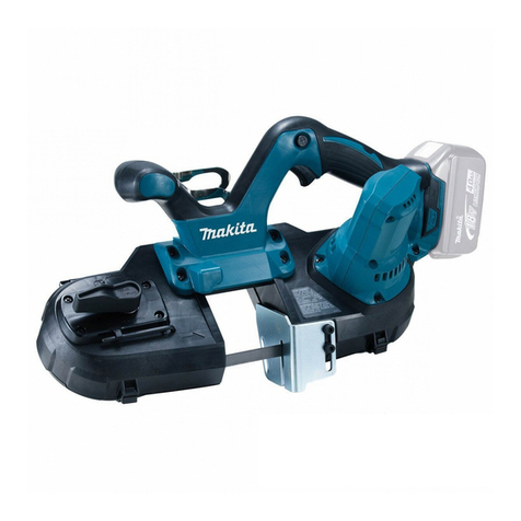
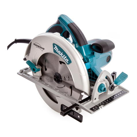
Makita 5077B User manual

185
mm
(744”)
MODEL
5077B
Equlpped
wlth
Electric
Blade Brake
Blade diameter
185
mm
(7-1/4”)
INSTRUCTION MANUAL
Max. cutting capacity
No
load speed Overall length Net weight
62
mm
(2-318”) 4,300 Rimin. 439
mm
(17.114”) 6.3 kg (13.9
Ibs)
DOUBLE
INSULATION
SPEC
IF
I
CAT
IONS

IMPORTANT
SAFETY
INSTRUCTIONS
(For All
Tools)
WARNING: When usingelectrictools, basicsafety precautions
should
always
be
followed to reducethe risk of fire, electric
shock, and personalinjury, includingthe following:
READ
ALL
INSTRUCTIONS.
1.
2.
3.
4.
5.
6.
7.
8.
9.
10.
11.
12.
13.
14.
15.
16.
2
Keepwork area clean.
Clutteredareas and benchesinvite injuries.
Considerwork area environment.
Do
not use powertools in damp or wet
locations. Keepwork areawell lit.
Do
notexpose powertoolsto rain.
Do
not
usetool in presenceof flammable liquidsor gases.
Keepchildren away.
All
visitorsshouldbe kept away from work area.
Do
not
letvisitors contact
tool
or extensioncord.
Store idletools.
When not in use,
tools
shouldbe locked-upor stored ina
dry, highplace
-
out of reachof children.
Do not force tool.
It
will do thejob betterandsafer at the ratefor which it was
intended.
Usecorrecttool.
Do
notforce smalltool or attachmentto do the job
of
a
heavy-dutytool.
Do
not use
tool
for purposenot intended;for example,don’t
usecircularsaw for cuttingtree limbsor logs.
Dressappropriately.
Do
notwear looseclothingor jewelry. They can be
caught in movingparts. Rubber glovesand non-skidfootwear are
recommendedwhen workingoutdoors. Wear protectivehaircovering
to
containlong hair.
Use safety glasses.
Also
useface or dust mask
if
cuttingoperationis dusty.
Do not abuse cord.
Never carrytool by cord or yank it
to
disconnectfrom
receptacle. Keepcord from heat,oil, and sharp edges.
Secureworkpiece.
Useclampsor a viseto holdwork. It is safer than using
your hand; it also leavesboth handsfree
to
operatetool.
Do
not over-reach.
Keepproperfooting and balanceat all times.
Maintaintools with care.
Keeptools sharp and cleanfor betterand safer
performance. Follow instructionsfor lubricatingandchangingaccessories.
Inspecttoolcords periodicallyand, if damaged, have repairedby authorized
servicefacility. Inspectextensioncords periodicallyand replace
if
damaged.
Keephandlesdry,clean, and free fromoil and grease.
Disconnecttools
when not in use, beforeservicing,and when changing
accessories, suchas blades,bits, and cutters.
Removeadjusting keysand wrenches.
Checkto ensurethat keysand
adjustingwrenches are removedfrom
tool
beforeturningthe tool on.
Avoid unintentionalstarting.
Do
notcarry plugged-intool with finger on
switch. Be sure switchis OFF when pluggingin.
Checkdamaged parts.
Beforefurther useof the
tool,
a guardor other part
that is damaged shouldbecarefullycheckedto determinethat it will operate
properlyand performits intendedfunction. Checkfor alignmentof moving
parts, bindingof movingparts, breakageof parts, mounting,andany other
conditionsthat may affecttool operation.
A
guardor other partthat is damaged
shouldbe properlyrepairedor replacedby an authorizedservicecenter unless
otherwiseindicatedelsewhere
in
this instructionmanual. Defectiveswitches
shouldbe replacedby an authorizedservicecenter.
Do
not usetool
if
the
switchdoes
not
turn it on andoff.
17.
Extensioncords.
Makesure your extensioncord isin
good
condition. When
using an extensioncord, be sure
to
use one heavyenough
to
carry the current
your productwilldraw. An undersizedcordwill cause a drop in linevoltage
resulting in
loss
of powerandoverheating. Table
1
showsthe correct size
to
use dependingon cord length and nameplateampere rating. If in doubt, use
the nextheavier gauge. The smaller the gauge number, the heavierthe cord.
Table
1.
MINIMUM
GAUGE
FOR CORD
SETS
0-6
6
-
10
10
-
12
I
12
-
16
I
Ampere Rating
More
NotMore
Than
Than
18
18
16
14
Total Length
of
Cord in Feet
0-25
1
26-50
1
51-100
1
101-150
16 16 14
16 14 12
16 14 12
12
Not
recommended
I
AWG
I
18.
Outdoor useextensioncords.
When
tool
is usedoutdoors, use only
extensioncords intendedfor outdoor useand
so
marked.
19.
Stay alert.
Watch what you are doing.
Do
not operatetoolwhen you are tired.
20.
Guard againstelectric shock.
Preventbody contact with groundedsurfaces,
for example: pipes, radiators, ranges, refrigerator enclosures.
21.
Replacementparts.
When servicing,
use
only identical replacementpart.
22.
Polarizedplugs:
To
reducethe risk of electric shock, this equipmenthas a
polarizedplug(one blade is wider thanthe other). This plugwill fit ina
polarized outlet only one way.
If
the plugdoes not fit fully inthe outlet, reverse
the plug.
If
it stilldoes not fit, contact a qualifiedelectrician
to
installthe proper
outlet.
Do
not changethe plug in any way.
3

VOLTAGE WARNING:
Before connectingthe tool to a powersource
(receptacleoutlet,etc.) be surethe voltage suppliedis the same as that
specifiedon the nameplateof the tool.
A
powersource with voltage greater
thanthat specifiedfor the tool can result in SERIOUS INJURYto the user,as
well as damage the tool.
If
in doubt,
DO
NOT PLUG IN
THE
TOOL.
Usinga
powersourcewith voltagelessthanthe nameplateratingis harmfulto the
motor.
4

ADDITIONAL SAFETY RULES
1.
Keep Guards In Place and In Working Order.
Never wedge or tie lower guard open. Check operation of lower guard be-
fore eachuse. Don’t use
if
lower guarddoes not close briskly over saw blade.
CAUTION:
If
saw isdropped, lowerguard may be bent, restrictingfull return.
2.
Keep Blades Clean and Sharp.
Sharp blades minimize stalling and kickback.
3.
DANGER: Keep Hands Away From Cutting Area.
Keep hands away
from
blades. Don’t reach underneath work while blade
is rotating. Don’t attempt to remove cut material when blade
is
moving.
CAUTION: Blades coast after turn off.
Largepanels must be supportedas
shown
in
Fig.
1
tominimizethe risk
of blade pinching and kickback.
When cutting operation requires
the restingof thesaw onthework
piece, the saw shall be rested on
the larger portion and the smaller
piece cut off.
4.
Support Large Panels.
6+4!k=a
To avoid
kickback,
do support board
or panel near the cut.
Fig.
Don‘t
support board or panel away
from the cut.
Fig.
2
5.
Use Rip Fence.
6.
Guard Against Kickback.
Always use a fence or straight edge guide when ripping.
Kickback occurs when the saw stalls rapidly and is driven back towards the
operator. Releaseswitch immediatelyif blade binds or saw stalls. Keep blades
sharp. Support large panels as shown in Fig.
1.
Use fence or straight edge
guide when ripping. Don’t force tool. Stay alert exercise control. Don’t re-
move saw from work during a cut while
the
blade is moving.
5

NEVER place your hand or fingers
behindthe saw. If kickback occurs,
the saw could easily jump back-
wards over your hand, possibly
causing severe injury.
Fig.
7.
Lower Guard. Raise lower guard
with
the retracting handle.
8.
Adjustments. Beforecutting be sure depth and beveladjustments are tight.
9.
Use Only Correct Blades
In
Mounting. Don’t use blades with incorrect size
IO.
Avoid Cutting Nails. Inspect for and remove all nails from lumber before
holes. Never use defective or incorrect blade washers or bolts.
cutting.
11.
When operatingthe saw, keepthe
cord away from the cutting area
andposition
it
so
that
it
will not be
caught on the workpiece during
the cutting operation.
Operate
with
proper hand support,
proper workpiece support, and
supply cordroutingaway from the
work area.
A
typical illustration
of
proper hand
support, workpiece support, and
supply cord routing.
WARNING:
It
isimportanttosupport the workpiece properly and tohold the saw firmly
toprevent
loss
of controlwhich could cause personalinjury. Fig.
4
illustrates
typical hand support of the saw.
6

12.
Placethe wider portionof the saw base on that part of the workpiece which
issolidly supported, notonthe sectionthat will fall off whenthe cut is made.
As
examples, Fig.
5
illustrates the RIGHT way tocut off the end
of
a
board,
andFig.
6
the WRONG way. Ifthe workpiece
is
short or small, clamp
it
down.
DON'T TRY TO HOLD SHORT PLECES BY HAND!
Fig. Fig.
13.
Neverattempt tosaw withthe cir-
cular saw held upside down in a
14.
Before setting the tool down after completing a cut, be sure that the lower
(telescoping)guard has closed and the blade has come to a complete stop.
SAVE
THESE INSTRUCTIONS.
7

Removing
or
installingsaw blade
CAUTION
:
Always
be
sure that the tool
is
switched off and unplugged before removingor installing
the blade.
To remove the blade, press the shaft lock
so
that the blade cannot revolve and use
the wrench to loosen the hex bolt clock-
wise. Then remove the hex bolt, outer
flange and blade.
To
install the blade, follow the removal
procedure in reverse. BE SURE TO
TIGHTEN THE HEX BOLT SECURELY.
CAUTION
:
.Be sure the blade
is
installed with teeth
pointingup
at
the front of the tool.
*Use only the Makita wrenches to install
or remove the blade.
*One side
of
the inner flange
is
for
5/8"
hole diameter of the blade; the other side
is
for
13/16"
holediameter.
inner flange
\
Fig.
9
Blade Outer flange
I
Fig.
1(
Use the correct side for the hole diameter of the blade you intend to use. Mounting the
bladeon the wrong side can result indangerous vibration.
a

Adjustingdepth
of
cut
Loosen
the
lever
on
the
depth guide and
move the base up or down. At the desired
depth of cut, secure the base
by
tightening
the lever.
Fig. 1
CAUTION
:
Use
a
shallow depth of cutwhen cutting thinworkpiece for cleaner, safer cuts.
*After adjustingthe depth of cut, always tighten the lever securely.
Bevel
cutting
Loosen
the lever onthe bevel
scale
plateon
the front of the
base.
Set
for
the desired
angle
(0"
-45')
by tiltingaccordingly,then
tighten the lever securely.
Sighting
For straight cuts, alignthe
left
notch inthe
front of the base with your cutting line on
the workpiece. For
45"
bevel cuts, align
the right notchwith
it.
Bevel
scale plats
For straight
For
45"
cuts bevel
cuts
Base plate
I1
I
Fig.
1
9

Switch action
To
start the tool, simply pull the trigger.
Release
the trigger
to
stop.
CAUTION
:
Before plugging in the tool, always check
to
see
that the trigger switch actuates pro-
perly and returns to the
"OFF"
position
when released.
Operation
Grasp the rear handle with your right hand,
the front grip with your
left.
Set
the base
plate on the workpiece to be cut without
the blade making any contact. Then turn
the tool on and wait untilthe blade attains
full speed. Now simply move the tool for-
ward over the workpiece surface, keeping
it
flat and advancing smoothly until the
sawing
is
completed.
To
get
clean cuts,
keep your sawing line straight and your
speed of advance uniform.
Guide rule
The handy guide rule allows you to do
extra-accurate straight cuts. Simply slide
the guide rule up snugly against the side
of the workpiece and secure
it
in position
with the wing bolton the front of the base.
It
also makes repeated cuts of uniform
workpiecewidth possible, too.
Trigger
switch
-
Fie.
1!
Fig.
16
10

MAINTENANCE
CAUTION
:
Always be sure that the tool
is
switched off and unplugged before attempting
to
perform
inspection or maintenance.
Replacingcarbon brushes
Remove and check the carbon brushes
regularly. Replace when they wear down
to the limit mark. Keep the carbon brushes
clean and free to slip in the holders. Both
carbon brushes should be replaced
at
the
sametime. Use only Makitacarbon brushes.
Use
a
screwdriver to remove the brush
holder caps. Take out the worn carbon
brushes, insert the new ones and secure the
brush holder caps.
I
Limit
mark
Fig.
1'
Screwdriver
I
1
Fig.
18
To
maintain product SAFETY and RELIABILITY, repairs, any other maintenance or
adjustment should be performed by Makita Authorized or Factory Service Centers,
always using Makita replacement parts.

OPTIONAL
ACCESSORIES
The accessorieslistedinthis manualareavailableatanextracostfromyour Makitadistributoror Makitafactory
servicecenter. Servicecenters are listedon the warrantycardpackedwithyour
tool.
CAUTION
:
These accessories or attachments are recommendedfor use with your Makita tool specified in this
manual. The use of any other accessories or attachments might present
a
risk of injury to persons.
The accessories
or
attachmentsshould
be
used only inthe proper and intended manner.
Part
No.
Diameter
0
Guide
rule
Part
No.
164095-8
Hole
No.
diameter
teeth
0
Wrench
13
Part
No.
782016-4
Part
No.
0
Steel carrying
case
Part
No.
823204-5
Hole
No.
Diameter
diameter
teeth
Saws
Chiseltoothcombination saw blade
Hole
Part
No.
Diameter
diameter
For rip and cross-cutwork.
Most
frequently used for
general carpentry.
No.
teeth
Carbide-tipped
saw
blade
Faster,smoother, longer sawing
without blade sharpening.
Cuts wood, drywall, plastics,
hardwood, etc.
518”
7-1
14-
792446-1
I
(185
mm)
I
40
792436-4
I I
5/8”
I
20
Combinationsaw blade
I
1-
I
12

May-26-'87
US
185
mm
(7-1/4")
HYPOID
SAW
Model
5077B
Note The switch, noise suppressor and other part conftguratlons
may
differ from country
to
country.
13

MODEL
50778
'iLM
&
DESCRIPTION
May-26-'87
US
'iLM
At.,
DESCRIPTION
MACHINE
1
2
3
4
5
6
7
8
9
10
11
12
13
14
15
16
17
19
20
21
22
23
24
25
26
27
28
29
30
31
32
33
34
36
37
38
39
40
1s
-
1
1
1
1
1
1
1
1
1
1
3
1
1
1
1
1
1
1
1
3
1
1
1
2
1
4
4
2
2
1
1
1
1
2
1
1
1
1
4
-
Hex
Flange
Hesd
Bolt
M8x20
Outer
Flange
40
Inner Flange
40
Spindle
Woodruff
Key
4
Bearing
Retainer
23-36
Ball
Bearing
6003LLB
Retaining
Ring
5-42
Safety
Cover
Tension Spring
4
Pan
Head
Screw
M5x20
!With Washer]
Bsarlng
BOX
Hex
Socket Head Bolt M6x12
Rubber
Pin
4
Retaining
Ring
S-16
Hypoid
Gear36
Sleeve
16
Blade
Care
Hex
Socket Head
Bolt
M6x25
!With Warherl
Rubber
Sleeve
6
Countersunk Head
Screw
M6x28
Indication
Label
Rivet
0-5
Name
Plate
Flat
Washer
5
Hex
Socket
Head
Bolt
M5x30
Brush
Holder
Cap
Carbon Brush
Motor
Housing
Cord
Cord Guard
Strain
Relief
Pan
Head
Screw
M4x18
lWith Washer)
Handle
Cover
Rubber
Pin
4
Switch
Dust
cover
Pan
Head
Screw
M4x25
IWRh Washer)
~aii
BearlngwLLe
MACHINE
41
42
43
44
45
46
47
48
49
50
51
52
53
54
55
56
57
58
59
60
61
62
63
64
65
66
67
68
69
70
71
72
73
74
75
76
77
76
-
2
2
1
1
1
1
1
1
1
1
1
1
3
1
1
1
1
1
2
1
1
1
1
1
1
1
1
1
1
1
1
1
1
1
1
1
1
1
-
Hex
Socket
Head
Bolt M5x14
Flat
Washer
5
Side Grip
LWB,
Pan
Head
Screw
M4x10
IWith Washed
Ring Spring
8
Pin
6
Retaining
Ring
S-
17
Gear
Housing
Seal
Ring 17
Ball Bearing
6203LLB
Binding Head
Screw
M5x12
Fan
92
ARMATURE ASSEMBLY
lWith
Item 52
&
54
-
571
Insulation
Washer
Ball
Bearing
608LB
Baffle
Plate
Hex
Bolt M5x65
lWith Washer]
FIELD ASSEMBLY
Flat
Washer
8
Base
wing
em
~5x10
Cap
Square
Neck
Bolt M8x24
Screw
M5x12
Flat
Washer
8
Flat
Washer
8
LeYe,
Plate
Lock
Plate
Hex
Nut
MB
Pan
Head
Screw
M4xB
IWith Warherl
Spring
Pin
6-45
Hex
Bolt
M8x28
Lock
Plate
Lever
Plate
Flat
Washer
8
Flat
Washer
8
Pan
Hesd
Screw
M4x8
(With
Washer)
compresrlon
sprmg
7
Note:
The switch
and
other part specifications
may
differ from country
to
country.
14

MAKITA
LIMITED
ONE
YEAR WARRANTY
Warranty
Policy
Every Makita tool is thoroughly inspected and tested before leaving the factory.
It
is warranted to
be free of defects from workmanship and materials for the period
of
ONE YEAR from the date
of
original purchase. Should any trouble develop during this one-year period, retum the COMPLETE
tool,
freight prepaid, toone of Makita’s Factory or Authorized Service Centers.
If
inspection
shows
the trouble is caused by defective workmanship
or
material, Makita will repair
(or
at our option,
replace) without charge.
This Warranty does not apply where:
repairs have been made or attempted by others:
repairs are required because of normal wear and tear:
The
tool
has been abused, misused or improperly maintained;
alterations have been made
to
the
tool.
IN NO EVENT SHALL MAKITA BE LIABLE FOR ANY INDIRECT, INCIDENTAL OR CON-
SEQUENTIAL DAMAGES FROM THE SALE OR USE OFTHE PRODUCT. THIS DISCLAIMER
APPLIES BOTH DURING AND AFTER THE TERM OFTHIS WARRANTY.
MAKITA DISCLAIMS LIABILITY FOR ANY IMPLIED WARRANTIES, INCLUDING IMPLIED
WARRANTIES OF “MERCHANTABILITY” AND “FITNESS FOR A SPECIFIC PURPOSE,”
AFTER THE ONE-YEAR TERM OFTHIS WARRANTY.
This Warranty gives you specific legal rights, and you may also have other rights which vary from
state to state. Some states do not allow the exclusion or limitation
of
incidental or consequential
damages,
so
the above limitation or exclusion may not apply to you. Some states do not allow
limitation on how long an implied warranty lasts,
so
the above limitation may not apply
to
you.
c___
MakitaCorporation
of
America
2650
Gainesville
Hwy
Buford,
GA
305
18
MCA
-
a195
883588E065
PRINTED
IN
U.S.A.
1995-9-c
Other manuals for 5077B
1
Table of contents
Other Makita Saw manuals

Makita
Makita JR3060T User manual

Makita
Makita LS1216 Manual

Makita
Makita BJR141 Manual

Makita
Makita JR3061T User manual

Makita
Makita 5402-A User manual

Makita
Makita LS1040F User manual

Makita
Makita LS0815F User manual

Makita
Makita LS0816F User manual

Makita
Makita 5603R User manual

Makita
Makita LS1216 User manual

Makita
Makita M5802B User manual

Makita
Makita LS1221 Quick start guide

Makita
Makita JR3000V User manual

Makita
Makita 5007NB-A Quick start guide

Makita
Makita LS1011N User manual

Makita
Makita RJ01 User manual

Makita
Makita LS1011N Manual

Makita
Makita DLS110 User manual

Makita
Makita LS0714 User manual

Makita
Makita HS7601 Manual