Makita LS1018 User manual

LS1018
LS1018L
EN Slide Compound Miter Saw INSTRUCTION MANUAL 10
RU Торцовочная пила
консольного типа
РУКОВОДСТВО ПО
ЭКСПЛУАТАЦИИ 23
KK Консоль типті
қапталдық ара
ПАЙДАЛАНУ ЖӨНІНДЕГІ
НҰСҚАУЛЫҚ 40

1
11
1
3
2
1
1
1
2
Fig.1
Fig.2
Fig.3
Fig.4
Fig.5
Fig.6
Fig.7
2

1
2
3
4
5
6
Fig.8
1
2
2
1
3
12
1
2
3
4
1
1
2
3
4
Fig.9
Fig.10
Fig.11
Fig.12
Fig.13
Fig.14
3

1
1
2
3
1
12
3
1
1
Fig.20
1
Fig.15
Fig.16
Fig.17
Fig.18
Fig.19
Fig.21
Fig.22
4

1
2
1
12
3
45
1
23
4
5
12
3
4
1
2
3
45
6
12
3
45
Fig.23
Fig.24
Fig.25
Fig.26
Fig.27
Fig.28
Fig.29
5

Fig.30
1
2
3
12
1
2
1
1
2
12
3
4
5
Fig.31
Fig.32
Fig.33
Fig.34
Fig.35
Fig.36
6

1
23
1
Fig.39
1
Fig.40
123
Fig.37
Fig.38
Fig.41
Fig.42
7

2
(1)
(2)
(1)
(2)
(2)
(1)
(2)
(1)
(1)
(2)
(3)
(4)
1
1
2
3
4
5
1
2
3
4
1
1
2
3
1
2
1
2
3
Fig.43
Fig.44
Fig.45
Fig.46
Fig.47
Fig.48
Fig.49
Fig.50
8

1
2
1
2
1
2
3
1
2
3
12
1
2
Fig.51
Fig.52
Fig.53
Fig.54
Fig.55
Fig.56
Fig.57
9

10 ENGLISH
ENGLISH (Original instructions)
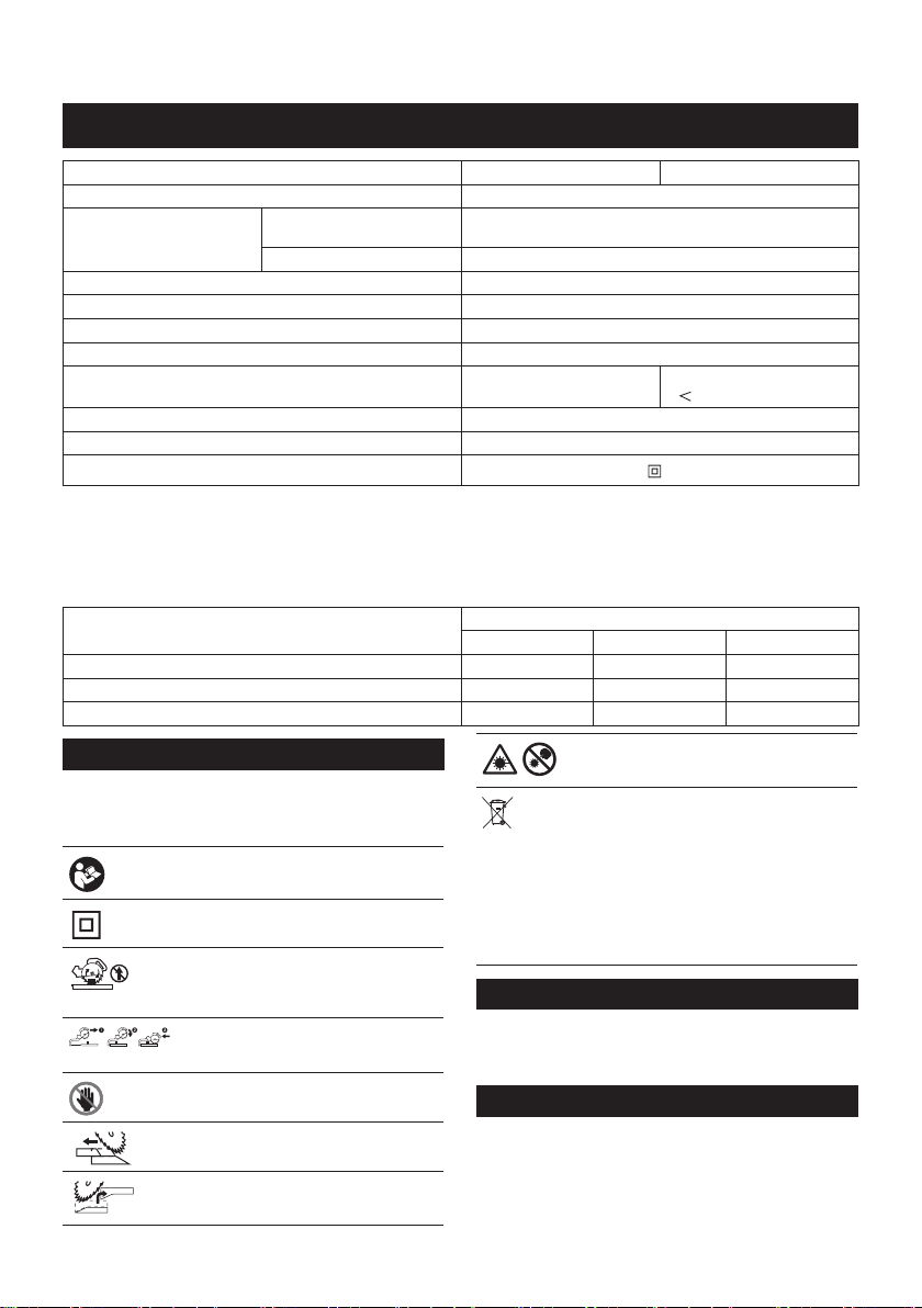
SPECIFICATIONS
Model: LS1018 LS1018L
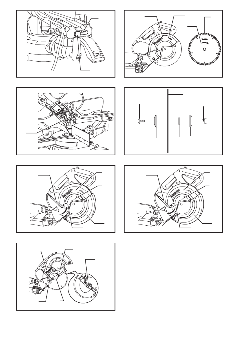
Blade diameter 255 - 260 mm
Hole diameter Countries other than Europe 25.4 mm or 30 mm
(country specic)
European countries 30 mm
Max. kerf thickness of the saw blade 3.2 mm
Max. miter angle Right 60°, Left 47°
Max. bevel angle Right 45°, Left 45°
No load speed (RPM) 4,300 min-1
Laser type -
Red Laser 650 nm, Maximum output
1 mW ( Laser Class 2M )
Dimensions (L x W x H) 825 mm x 536 mm x 633 mm
Net weight 21.5 kg
Safety class /II
• Due to our continuing program of research and development, the specications herein are subject to change
without notice.
• Specications may differ from country to country.
• Weight according to EPTA-Procedure 01/2014
Max. Cutting capacities (H x W) with 260 mm in diameter
Miter angle Bevel angle
45° (left) 0° 45° (right)
0° 50 mm x 310 mm 91 mm x 310 mm 31 mm x 310 mm
45° 50 mm x 220 mm 91 mm x 220 mm 31 mm x 220 mm
60° (right) -91 mm x 153 mm -
Symbols
The following show the symbols used for the equip-
ment. Be sure that you understand their meaning before
use.
Read instruction manual.
DOUBLE INSULATION
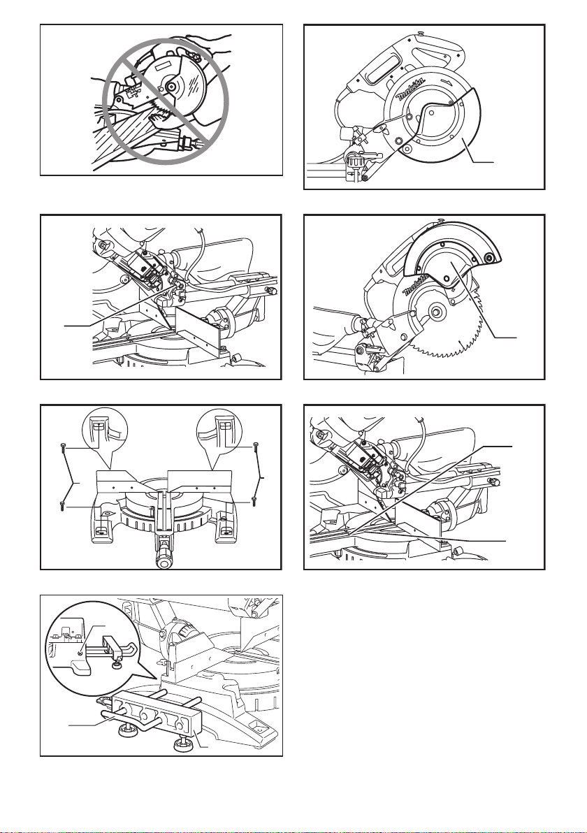
To avoid injury from ying debris, keep
holding the saw head down, after making
cuts, until the blade has come to a com-
plete stop.
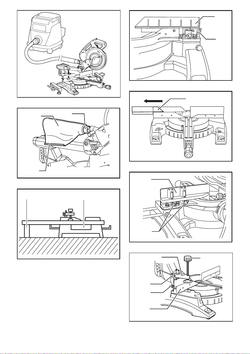
When performing slide cut, rst pull car-
riage fully and press down handle, then
push carriage toward the guide fence.
Do not place hand or ngers close to the
blade.
Adjust sliding fences clear of blade and
blade guard properly.
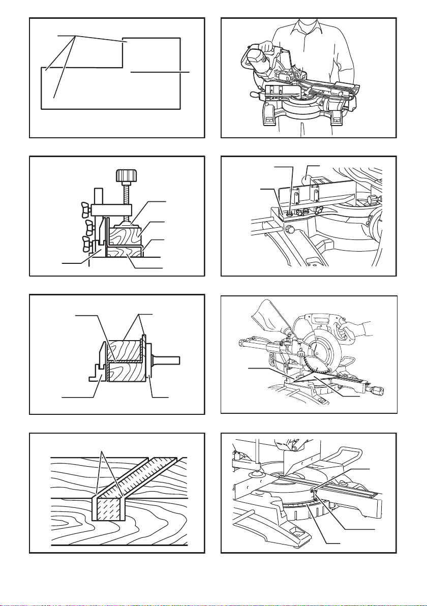
Always remove SUB-FENCE R when
performing right bevel cuts. Failure to do so
may cause serious injury to operator.
LASER RADIATION: Do not stare into
beam. Direct laser beam may injure your
eyes.
Only for EU countries
Do not dispose of electric equipment
together with household waste material!
In observance of the European Directive,
on Waste Electric and Electronic
Equipment and its implementation in
accordance with national law, electric
equipment that have reached the end of
their life must be collected separately and
returned to an environmentally compatible
recycling facility.
Intended use
The tool is intended for accurate straight and miter
cutting in wood. With appropriate saw blades, aluminum
can also be sawed.
Power supply
The tool should be connected only to a power supply of
the same voltage as indicated on the nameplate, and
can only be operated on single-phase AC supply. They
are double-insulated and can, therefore, also be used
from sockets without earth wire.

11 ENGLISH
Noise
The typical A-weighted noise level determined accord-
ing to EN62841-3-9:
Sound pressure level (LpA) : 92 dB(A)
Sound power level (LWA) : 102 dB (A)
Uncertainty (K) : 3 dB(A)
NOTE:
The declared noise emission value(s) has been
measured in accordance with a standard test method
and may be used for comparing one tool with another.
NOTE:
The declared noise emission value(s) may
also be used in a preliminary assessment of exposure.
WARNING: Wear ear protection.
WARNING:
The noise emission during actual
use of the power tool can differ from the declared val-
ue(s) depending on the ways in which the tool is used
especially what kind of workpiece is processed.
WARNING:
Be sure to identify safety measures
to protect the operator that are based on an estima-
tion of exposure in the actual conditions of use (tak-
ing account of all parts of the operating cycle such
as the times when the tool is switched off and when
it is running idle in addition to the trigger time).
EC Declaration of Conformity
For European countries only
The EC declaration of conformity is included as Annex A
to this instruction manual.
SAFETY WARNINGS
General power tool safety warnings
WARNING:
Read all safety warnings, instruc-
tions, illustrations and specications provided with this
power tool. Failure to follow all instructions listed below
may result in electric shock, re and/or serious injury.
Save all warnings and instruc-
tions for future reference.
The term "power tool" in the warnings refers to your mains-oper-
ated (corded) power tool or battery-operated (cordless) power tool.
Work area safety
1. Keep work area clean and well lit. Cluttered or
dark areas invite accidents.
2. Do not operate power tools in explosive atmo-
spheres, such as in the presence of ammable
liquids, gases or dust. Power tools create sparks
which may ignite the dust or fumes.
3.
Keep children and bystanders away while operating a
power tool. Distractions can cause you to lose control.
Electrical Safety
1.
Power tool plugs must match the outlet. Never modify
the plug in any way. Do not use any adapter plugs with
earthed (grounded) power tools. Unmodied plugs and
matching outlets will reduce risk of electric shock.
2. Avoid body contact with earthed or grounded
surfaces, such as pipes, radiators, ranges and
refrigerators. There is an increased risk of elec-
tric shock if your body is earthed or grounded.
3. Do not expose power tools to rain or wet con-
ditions. Water entering a power tool will increase
the risk of electric shock.
4.
Do not abuse the cord. Never use the cord for carrying,
pulling or unplugging the power tool. Keep cord away
from heat, oil, sharp edges or moving parts. Damaged
or entangled cords increase the risk of electric shock.
5.
When operating a power tool outdoors, use an exten-
sion cord suitable for outdoor use. Use of a cord suit-
able for outdoor use reduces the risk of electric shock.
6. If operating a power tool in a damp location
is unavoidable, use a residual current device
(RCD) protected supply. Use of an RCD reduces
the risk of electric shock.
7. Use of power supply via an RCD with a rated
residual current of 30 mA or less is always
recommended.
8.
Power tools can produce electromagnetic elds
(EMF) that are not harmful to the user. However,
users of pacemakers and other similar medical
devices should contact the maker of their device and/
or doctor for advice before operating this power tool.
9. Do not touch the power plug with wet hands.
10.
If the cord is damaged, have it replaced by the manu-
facturer or his agent in order to avoid a safety hazard.
Personal Safety
1. Stay alert, watch what you are doing and use
common sense when operating a power tool.
Do not use a power tool while you are tired or
under the inuence of drugs, alcohol or med-
ication. A moment of inattention while operating
power tools may result in serious personal injury.
2.
Use personal protective equipment. Always wear eye
protection. Protective equipment such as a dust mask,
non-skid safety shoes, hard hat or hearing protection used
for appropriate conditions will reduce personal injuries.
3. Prevent unintentional starting. Ensure the
switch is in the off-position before connecting
to power source and/or battery pack, picking
up or carrying the tool. Carrying power tools with
your nger on the switch or energising power tools
that have the switch on invites accidents.
4.
Remove any adjusting key or wrench before turning
the power tool on. A wrench or a key left attached to a
rotating part of the power tool may result in personal injury.
5. Do not overreach. Keep proper footing and
balance at all times. This enables better control
of the power tool in unexpected situations.
6. Dress properly. Do not wear loose clothing or
jewellery. Keep your hair and clothing away
from moving parts. Loose clothes, jewellery or
long hair can be caught in moving parts.
7. If devices are provided for the connection of
dust extraction and collection facilities, ensure
these are connected and properly used. Use of
dust collection can reduce dust-related hazards.
8.
Do not let familiarity gained from frequent use
of tools allow you to become complacent and
ignore tool safety principles. A careless action can
cause severe injury within a fraction of a second.

12 ENGLISH
9.
Always wear protective goggles to protect your eyes
from injury when using power tools.The goggles
must comply with ANSI Z87.1 in the USA, EN 166 in
Europe, or AS/NZS 1336 in Australia/New Zealand. In
Australia/New Zealand, it is legally required to wear
a face shield to protect your face, too.
It is an employer's responsibility to enforce
the use of appropriate safety protective equip-
ments by the tool operators and by other per-
sons in the immediate working area.
Power tool use and care
1. Do not force the power tool. Use the correct
power tool for your application. The correct
power tool will do the job better and safer at the
rate for which it was designed.
2.
Do not use the power tool if the switch does not turn
it on and off. Any power tool that cannot be controlled
with the switch is dangerous and must be repaired.
3. Disconnect the plug from the power source
and/or remove the battery pack, if detachable,
from the power tool before making any adjust-
ments, changing accessories, or storing power
tools. Such preventive safety measures reduce
the risk of starting the power tool accidentally.
4.
Store idle power tools out of the reach of children and
do not allow persons unfamiliar with the power tool
or these instructions to operate the power tool. Power
tools are dangerous in the hands of untrained users.
5.
Maintain power tools and accessories. Check for
misalignment or binding of moving parts, break-
age of parts and any other condition that may
affect the power tool’s operation. If damaged, have
the power tool repaired before use. Many accidents
are caused by poorly maintained power tools.
6. Keep cutting tools sharp and clean. Properly
maintained cutting tools with sharp cutting edges
are less likely to bind and are easier to control.
7.
Use the power tool, accessories and tool bits etc.
in accordance with these instructions, taking into
account the working conditions and the work to be
performed. Use of the power tool for operations different
from those intended could result in a hazardous situation.
8.
Keep handles and grasping surfaces dry, clean
and free from oil and grease. Slippery handles and
grasping surfaces do not allow for safe handling and
control of the tool in unexpected situations.
9. When using the tool, do not wear cloth work
gloves which may be entangled. The entangle-
ment of cloth work gloves in the moving parts may
result in personal injury.
Service
1. Have your power tool serviced by a qualied
repair person using only identical replacement
parts. This will ensure that the safety of the power
tool is maintained.
2. Follow instruction for lubricating and chang-
ing accessories.
Safety instructions for mitre saws
1. Mitre saws are intended to cut wood or wood-
like products, they cannot be used with abra-
sive cut-off wheels for cutting ferrous material
such as bars, rods, studs, etc. Abrasive dust
causes moving parts such as the lower guard to
jam. Sparks from abrasive cutting will burn the
lower guard, the kerf insert and other plastic parts.
2.
Use clamps to support the workpiece whenever pos-
sible. If supporting the workpiece by hand, you must
always keep your hand at least 100 mm from either side
of the saw blade. Do not use this saw to cut pieces that
are too small to be securely clamped or held by hand. If
your hand is placed too close to the saw blade, there is an
increased risk of injury from blade contact.
3.
The workpiece must be stationary and clamped or
held against both the fence and the table. Do not
feed the workpiece into the blade or cut "freehand"
in any way. Unrestrained or moving workpieces could
be thrown at high speeds, causing injury.
4.
Push the saw through the workpiece. Do not pull
the saw through the workpiece. To make a cut,
raise the saw head and pull it out over the work-
piece without cutting, start the motor, press the
saw head down and push the saw through the
workpiece. Cutting on the pull stroke is likely to cause
the saw blade to climb on top of the workpiece and vio-
lently throw the blade assembly towards the operator.
5.
Never cross your hand over the intended line of
cutting either in front or behind the saw blade.
Supporting the workpiece "cross handed" i.e. hold-
ing the workpiece to the right of the saw blade with
your left hand or vice versa is very dangerous.
► Fig.1
6. Do not reach behind the fence with either hand
closer than 100 mm from either side of the saw
blade, to remove wood scraps, or for any other
reason while the blade is spinning. The proxim-
ity of the spinning saw blade to your hand may not
be obvious and you may be seriously injured.
7. Inspect your workpiece before cutting. If the
workpiece is bowed or warped, clamp it with
the outside bowed face toward the fence.
Always make certain that there is no gap
between the workpiece, fence and table along
the line of the cut. Bent or warped workpieces
can twist or shift and may cause binding on the
spinning saw blade while cutting. There should be
no nails or foreign objects in the workpiece.
8.
Do not use the saw until the table is clear of all tools,
wood scraps, etc., except for the workpiece. Small
debris or loose pieces of wood or other objects that con-
tact the revolving blade can be thrown with high speed.
9.
Cut only one workpiece at a time. Stacked multiple
workpieces cannot be adequately clamped or braced
and may bind on the blade or shift during cutting.

13 ENGLISH
10. Ensure the mitre saw is mounted or placed on
a level, rm work surface before use. A level
and rm work surface reduces the risk of the mitre
saw becoming unstable.
11. Plan your work. Every time you change the
bevel or mitre angle setting, make sure the
adjustable fence is set correctly to support the
workpiece and will not interfere with the blade
or the guarding system. Without turning the tool
"ON" and with no workpiece on the table, move
the saw blade through a complete simulated cut to
assure there will be no interference or danger of
cutting the fence.
12. Provide adequate support such as table exten-
sions, saw horses, etc. for a workpiece that is
wider or longer than the table top. Workpieces
longer or wider than the mitre saw table can tip
if not securely supported. If the cut-off piece or
workpiece tips, it can lift the lower guard or be
thrown by the spinning blade.
13. Do not use another person as a substitute for
a table extension or as additional support.
Unstable support for the workpiece can cause the
blade to bind or the workpiece to shift during the
cutting operation pulling you and the helper into
the spinning blade.
14. The cut-off piece must not be jammed or
pressed by any means against the spinning
saw blade. If conned, i.e. using length stops, the
cut-off piece could get wedged against the blade
and thrown violently.
15. Always use a clamp or a xture designed to
properly support round material such as rods
or tubing. Rods have a tendency to roll while
being cut, causing the blade to "bite" and pull the
work with your hand into the blade.
16. Let the blade reach full speed before contact-
ing the workpiece. This will reduce the risk of the
workpiece being thrown.
17. If the workpiece or blade becomes jammed,
turn the mitre saw off. Wait for all moving
parts to stop and disconnect the plug from
the power source and/or remove the battery
pack. Then work to free the jammed material.
Continued sawing with a jammed workpiece could
cause loss of control or damage to the mitre saw.
18. After nishing the cut, release the switch,
hold the saw head down and wait for the blade
to stop before removing the cut-off piece.
Reaching with your hand near the coasting blade
is dangerous.
19. Hold the handle rmly when making an incom-
plete cut or when releasing the switch before
the saw head is completely in the down posi-
tion. The braking action of the saw may cause
the saw head to be suddenly pulled downward,
causing a risk of injury.
20. Only use the saw blade with the diameter that
is marked on the tool or specied in the man-
ual. Use of an incorrectly sized blade may affect
the proper guarding of the blade or guard opera-
tion which could result in serious personal injury.
21. Only use the saw blades that are marked with
a speed equal or higher than the speed marked
on the tool.
22. Do not use the saw to cut other than wood,
aluminum or similar materials.
23. (For European countries only)
Always use the blade which conforms to
EN847-1.
Additional instructions
1. Make workshop kid proof with padlocks.
2. Never stand on the tool. Serious injury could
occur if the tool is tipped or if the cutting tool is
unintentionally contacted.
3. Never leave the tool running unattended. Turn
the power off. Do not leave tool until it comes
to a complete stop.
4. Do not operate saw without guards in place.
Check blade guard for proper closing before
each use. Do not operate saw if blade guard
does not move freely and close instantly.
Never clamp or tie the blade guard into the
open position.
5. Keep hands out of path of saw blade. Avoid
contact with any coasting blade. It can still
cause severe injury.
6. To reduce the risk of injury, return carriage
to the full rear position after each crosscut
operation.
7. Always secure all moving portions before
carrying the tool.
8. Stopper pin which locks the cutter head down
is for carrying and storage purposes only and
not for any cutting operations.
9. Check the blade carefully for cracks or dam-
age before operation. Replace cracked or dam-
aged blade immediately. Gum and wood pitch
hardened on blades slows saw and increases
potential for kickback. Keep blade clean by
rst removing it from tool, then cleaning it with
gum and pitch remover, hot water or kerosene.
Never use gasoline to clean blade.
10. While making a slide cut, KICKBACK can
occur. KICKBACK occurs when the blade
binds in the workpiece during a cutting oper-
ation and the saw blade is driven rapidly
towards the operator. Loss of control and seri-
ous personal injury can result. If blade begins
to bind during a cutting operation, do not con-
tinue to cut and release switch immediately.
11. Use only anges specied for this tool.
12.
Be careful not to damage the arbor, anges (espe-
cially the installing surface) or bolt. Damage to
these parts could result in blade breakage.
13. Make sure that the turn base is properly
secured so it will not move during operation.
Use the holes in the base to fasten the saw to a
stable work platform or bench. NEVER use tool
where operator positioning would be awkward.
14. Make sure the shaft lock is released before the
switch is turned on.
15. Be sure that the blade does not contact the
turn base in the lowest position.
16. Hold the handle rmly. Be aware that the saw
moves up or down slightly during start-up and
stopping.
17. Make sure the blade is not contacting the
workpiece before the switch is turned on.

14 ENGLISH
18. Before using the tool on an actual workpiece,
let it run for a while. Watch for vibration or
wobbling that could indicate poor installation
or a poorly balanced blade.
19. Stop operation immediately if you notice any-
thing abnormal.
20. Do not attempt to lock the trigger in the "ON"
position.
21. Always use accessories recommended in this
manual. Use of improper accessories such as
abrasive wheels may cause an injury.
22. Some material contains chemicals which may
be toxic. Take caution to prevent dust inhala-
tion and skin contact. Follow material supplier
safety data.
23. Do not use a corded power supply with this
tool.
Additional safety rules for the laser
1. LASER RADIATION, DO NOT STARE INTO THE
BEAM OR VIEW DIRECTLY WITH OPTICAL
INSTRUMENTS, CLASS 2M LASER PRODUCT.
SAVE THESE INSTRUCTIONS.
WARNING: DO NOT let comfort or familiarity
with product (gained from repeated use) replace
strict adherence to safety rules for the subject
product. MISUSE or failure to follow the safety
rules stated in this instruction manual may cause
serious personal injury.
INSTALLATION
Bench mounting
► Fig.2: 1. Stopper pin
When the tool is shipped, the handle is locked in the
lowered position by the stopper pin. Release the stop-
per pin by simultaneously applying a slight downward
pressure on the handle and pulling the stopper pin.
► Fig.3: 1. Bolts
This tool should be bolted with four bolts to a level and
stable surface using the bolt holes provided in the tool's
base. This will help prevent tipping and possible injury.
Installing the holders and holder
assemblies
NOTE: In some countries, the holders and holder
assemblies may not be included in the tool package
as standard accessory.
► Fig.4: 1. Holder 2. Holder assembly 3. Screw
The holders and the holder assemblies support work-
pieces horizontally.
Install the holders and the holder assemblies on both
side as shown in the gure.
Then tighten the screws rmly to secure the holders and
the holder assemblies.
FUNCTIONAL DESCRIPTION
WARNING:
• Always be sure that the tool is switched off
and unplugged before adjusting or checking
function on the tool. Failure to switch off and
unplug the tool may result in serious personal
injury from accidental start-up.
Blade guard
► Fig.5: 1. Blade guard
When lowering the handle, the blade guard rises auto-
matically. The blade guard returns to its original position
when the cut is completed and the handle is raised.
WARNING:
• Never defeat or remove the blade guard or
the spring which attaches to the guard. An
exposed blade as a result of defeated guarding
may result in serious personal injury during
operation.
In the interest of your personal safety, always maintain
the blade guard in good condition. Any irregular opera-
tion of the blade guard should be corrected immediately.
Check to assure spring loaded return action of guard.
WARNING:
•
Never use the tool if the blade guard or spring
are damaged, faulty or removed. Operation of
the tool with a damaged, faulty or removed guard
may result in serious personal injury.
If the see-through blade guard becomes dirty, or saw-
dust adheres to it in such a way that the blade and/or
workpiece is no longer easily visible, unplug the saw and
clean the guard carefully with a damp cloth. Do not use
solvents or any petroleum-based cleaners on the plastic
guard because this may cause damage to the guard.
If the blade guard becomes dirty and needs to be
cleaned for proper operation follow the steps below:
With the tool switched off and unplugged, use the sup-
plied socket wrench to loosen the hex bolt holding the
center cover. Loosen the hex bolt by turning it counter-
clockwise and raise the blade guard and center cover.
► Fig.6: 1. Blade guard
With the blade guard so positioned, cleaning can be
more completely and efciently accomplished. When
cleaning is complete reverse procedure above and
secure bolt. Do not remove spring holding blade guard.
If guard becomes damaged through age or UV light
exposure, contact a Makita service center for a new
guard. DO NOT DEFEAT OR REMOVE GUARD.
Positioning kerf board
► Fig.7: 1. Screw 2. Kerf board
► Fig.8:
1. Saw blade 2. Blade teeth 3. Kerf board 4. Left
bevel cut 5. Straight cut 6. Right bevel cut
This tool is provided with the kerf boards in the turn
base to minimize tearing on the exit side of a cut. The
kerf boards are factory adjusted so that the saw blade
does not contact the kerf boards. Before use, adjust the
kerf boards as follows:

15 ENGLISH
First, unplug the tool. Loosen all the screws (3 each on left and
right) securing the kerf boards. Re-tighten them only to the
extent that the kerf boards can still be easily moved by hand.
Lower the handle fully and push in the stopper pin to lock the
handle in the lowered position. Loosen the screw which secures
the slide poles. Pull the carriage toward you fully. Adjust the
kerf boards so that the kerf boards just contact the sides of the
blade teeth. Tighten the front screws (do not tighten rmly).
Push the carriage toward the guide fence fully and adjust the
kerf boards so that the kerf boards just contact the sides of
blade teeth. Tighten the rear screws (do not tighten rmly).
After adjusting the kerf boards, release the stopper pin and
raise the handle. Then tighten all the screws securely.
NOTICE:
•
After setting the bevel angle ensure that the kerf
boards are adjusted properly. Correct adjustment
of the kerf boards will help provide proper support of
the workpiece minimizing workpiece tear out.
Maintaining maximum cutting capacity
This tool is factory adjusted to provide the maximum
cutting capacity for a 255 mm saw blade.
Unplug the tool before any adjustment is attempted.
When installing a new blade, always check the lower limit
position of the blade and if necessary, adjust it as follows:
► Fig.9: 1. Adjusting bolt 2. Turn base
► Fig.10: 1. Top surface of turn base 2. Periphery of
blade 3. Guide fence
First, unplug the tool. Push the carriage toward the guide fence
fully and lower the handle completely. Use the hex. wrench to turn
the adjusting bolt until the periphery of the blade extends slightly
below the top surface of the turn base at the point where the front
face of the guide fence meets the top surface of the turn base.
With the tool unplugged, rotate the blade by hand while holding
the handle all the way down to be sure that the blade does not
contact any part of the lower base. Re-adjust slightly, if necessary.
WARNING:
• After installing a new blade and with the tool
unplugged, always be sure that the blade
does not contact any part of the lower base
when the handle is lowered completely. If a
blade makes contact with the base it may cause
kickback and result in serious personal injury.
Stopper arm
► Fig.11: 1. Stopper arm 2. Adjusting screw
The lower limit position of the blade can be easily
adjusted with the stopper arm. To adjust it, move the
stopper arm in the direction of the arrow as shown in the
gure. Adjust the adjusting screw so that the blade stops
at the desired position when lowering the handle fully.
Adjusting the miter angle
► Fig.12:
1. Miter scale 2. Pointer 3. Lock lever 4. Grip
Loosen the grip by turning counterclockwise. Turn the turn base
while pressing down the lock lever. When you have moved the
grip to the position where the pointer points to the desired angle
on the miter scale, securely tighten the grip clockwise.
CAUTION:
• After changing the miter angle, always secure
the turn base by tightening the grip rmly.
NOTICE:
• When turning the turn base, be sure to raise the
handle fully.
Adjusting the bevel angle
► Fig.13: 1. Lever
To adjust the bevel angle, loosen the lever at the rear of the tool
counterclockwise. Unlock the arm by pushing the handle some-
what strongly in the direction that you intend to tilt the saw blade.
NOTE:
• Lever can be adjusted to a different lever angle
by removing the screw holding the lever and
securing the lever at a desired angle.
► Fig.14: 1. Lever 2. Arm 3. Pointer 4. Bevel scale
Tilt the saw blade until the pointer points to the desired
angle on the bevel scale. Then tighten the lever clock-
wise rmly to secure the arm.
► Fig.15: 1. Lever
When tilting the carriage to the right, tilt the carriage to the left
slightly after loosening the lever and press the releasing button.
With the releasing button being pressed, tilt the carriage to the right.
► Fig.16: 1. Pointer 2. Release button 3. Bevel scale
Tilt the saw blade until the pointer points to the desired
angle on the bevel scale. Then tighten the lever clock-
wise rmly to secure the arm.
• When changing bevel angles, be sure to position
the kerf boards appropriately as explained in the
"Positioning kerf boards" section.
CAUTION:
• After changing the bevel angle, always secure
the arm by tightening the lever clockwise.
NOTICE:
• When tilting the saw blade be sure the handle is
fully raised.
• When changing bevel angles, be sure to position
the kerf boards appropriately as explained in the
"Positioning kerf boards" section.
Slide lock adjustment
► Fig.17: 1. Locking screw
To lock the slide pole, turn the locking screw clockwise.
Switch action
► Fig.18: 1. Lock-off button 2. Switch trigger 3. Hole
for padlock
To prevent the switch trigger from being accidentally pulled, a lock-
off button is provided. To start the tool, press in the lock-off button
and pull the switch trigger. Release the switch trigger to stop.
WARNING:
•
Before plugging in the tool, always check to see that
the switch trigger actuates properly and returns to
the "OFF" position when released. Do not pull the
switch trigger hard without pressing in the lock-off
button. This can cause switch breakage. Operating
a tool with a switch that does not actuate properly can
lead to loss of control and serious personal injury.
A hole is provided in the switch trigger for insertion of
padlock to lock the tool off.

16 ENGLISH
WARNING:
• Do not use a lock with a shank or cable any
smaller than 6.35 mm in diameter. A smaller
shank or cable may not properly lock the tool in
the off position and unintentional operation may
occur resulting in serious personal injury.
•
NEVER use tool without a fully operative switch
trigger. Any tool with an inoperative switch is
HIGHLY DANGEROUS and must be repaired before
further usage or serious personal injury may occur.
•
For your safety, this tool is equipped with a lock-off
button which prevents the tool from unintended
starting. NEVER use the tool if it runs when you
simply pull the switch trigger without pressing the
lock-off button. A switch in need of repair may
result in unintentional operation and serious per-
sonal injury. Return tool to a Makita service center
for proper repairs BEFORE further usage.
• NEVER defeat the lock-off button by taping
down or some other means. A switch with a
defeated lock-off button may result in uninten-
tional operation and serious personal injury.
Electronic function
Soft start feature
This function allows the smooth start-up of the tool by
limiting the start-up torque.
Laser beam action
For model LS1018L only
NOTE:
• Before the rst use, install two AA dry cells in the
cell box. Refer to the section titled "Replacing
the dry cells for laser unit" for the installment.
CAUTION:
• When not in use, be sure to turn off the laser.
► Fig.19: 1. Switch for laser
CAUTION:
• Never look into the laser beam. Direct laser
beam may injure your eyes.
• LASER RADIATION, DO NOT STARE INTO
THE BEAM, CLASS 2 LASER PRODUCT.
• Before shifting the laser line or performing main-
tenance adjustment, be sure to unplug the tool.
To turn on the laser beam, press the upper position (I) of the switch.
To turn off the laser beam, press the lower position (0) of the switch.
Laser line can be shifted to either the left or right side of the saw
blade by loosening the screw holding the laser unit box and shifting
it in the desired direction. After shifting, be sure to tighten the screw.
► Fig.20: 1. Screw holding the laser unit box
Laser line is factory adjusted so that it is positioned within
1 mm from the side surface of the blade (cutting position).
NOTE:
•
When laser line appears dim and hard to see
because of direct sunlight, relocate the work area
to a place where there is less direct sunlight.
Replacing the dry cells for laser unit
► Fig.21
► Fig.22: 1. Dry cell
Remove the lid for the dry cells for laser unit by sliding
while pressing it. Take out the old dry cells and put the
new ones as shown in the gure. After replacing, return
the lid to cover it.
Cleaning of the lens for the laser light
If the lens for the laser light becomes dirty, or sawdust
adheres to it in such a way that the laser line is no
longer easily visible, unplug the saw and remove and
clean the lens for the laser light carefully with a damp,
soft cloth. Do not use solvents or any petroleum-based
cleaners on the lens.
NOTE:
• When laser line is dim and almost or entirely
invisible because of the direct sunlight in the
indoor or outdoor window-by work, relocate the
work area to a place not exposed to the direct
sunlight.
ASSEMBLY
WARNING:
• Always be sure that the tool is switched off
and unplugged before working on the tool.
Failure to switch off and unplug the tool may
result in serious personal injury.
Storage of socket wrench with hex
wrench on its other end
► Fig.23: 1. Socket wrench with hex wrench on its
other end 2. Wrench holder
The socket wrench is stored as shown in the gure.
When the socket wrench is needed it can be pulled out
of the wrench holder. After using the socket wrench it
can be stored by returning it to the wrench holder.
Installing or removing saw blade
WARNING:
• Always be sure that the tool is switched off
and unplugged before installing or removing
the blade. Accidental start up of the tool may
result in serious personal injury.
•
Use only the Makita socket wrench provided
to install or remove the blade.Failure to use the
wrench may result in overtightening or insufcient
tightening of the hex bolt and serious personal injury.
► Fig.24: 1. Stopper pin
Lock the handle in the raised position by pushing in the stopper pin.
► Fig.25: 1. Socket wrench 2. Blade case 3. Center
cover 4. Hex bolt 5. Blade guard
To remove the blade, use the socket wrench to loosen
the hex bolt holding the center cover by turning it coun-
terclockwise. Raise the blade guard and center cover.

17 ENGLISH
WARNING:
• Do not remove any screw other than the
hex bolt illustrated. If you mistakenly remove
another screw and the blade guard comes off,
make sure to re-assemble the blade guard.
► Fig.26: 1. Blade case 2. Socket wrench 3. Hex bolt
4. Arrow 5. Shaft lock
Press the shaft lock to lock the spindle and use the
socket wrench to loosen the hex bolt clockwise. Then
remove the hex bolt, outer ange and blade.
NOTE:
• If the inner ange is removed be sure to install
it on the spindle with its protrusion facing away
from the blade. If the ange is installed incor-
rectly the ange will rub against the machine.
WARNING:
•
Before mounting the blade onto the spindle,
always be sure that the correct ring for the blade's
arbor hole you intend to use is installed between
the inner and the outer anges. Use of the incorrect
arbor hole ring may result in the improper mounting
of the blade causing blade movement and severe
vibration resulting in possible loss of control during
operation and in serious personal injury.
► Fig.27: 1. Blade case 2. Arrow 3. Arrow 4. Saw
blade
To install the blade, mount it carefully onto the spindle,
making sure that the direction of the arrow on the sur-
face of the blade matches the direction of the arrow on
the blade case.
Install the outer ange and hex bolt, and then use the
socket wrench to tighten the hex bolt (left-handed)
securely counterclockwise while pressing the shaft lock.
► Fig.28: 1. Hex bolt (left-handed) 2. Outer ange
3. Saw blade 4. Ring 5. Inner ange
6. Spindle
► Fig.29: 1. Socket wrench 2. Blade case 3. Center
cover 4. Hex bolt 5. Blade guard
Return the blade guard and center cover to its original
position. Then tighten the hex bolt clockwise to secure the
center cover. Release the handle from the raised position
by pulling the stopper pin. Lower the handle to make sure
that the blade guard moves properly. Make sure the shaft
lock has released spindle before making cut.
Connecting a vacuum cleaner
When you wish to perform clean cutting operation,
connect a Makita vacuum cleaner.
► Fig.30
Dust bag
► Fig.31: 1. Dust nozzle 2. Dust bag 3. Fastener
The use of the dust bag makes cutting operations
cleaner and dust collection easier. To attach the dust
bag, t it onto the dust nozzle.
When the dust bag is about half full, remove the dust
bag from the tool and pull the fastener out. Empty
the dust bag of its contents, tapping it lightly so as to
remove particles adhering to the insides which might
hamper further collection.
Securing workpiece
WARNING:
• It is extremely important to always secure
the workpiece correctly with the proper type
of vise or crown molding stoppers. Failure to
do so may result in serious personal injury and
cause damage to the tool and/or the workpiece.
•
After a cutting operation do not raise the
blade until it has come to a complete stop. The
raising of a coasting blade may result in serious
personal injury and damage to the workpiece.
•
When cutting a workpiece that is longer than the
support base of the saw, the material should be
supported the entire length beyond the support
base and at the same height to keep the material
level. Proper workpiece support will help avoid blade
pinch and possible kickback which may result in serious
personal injury. Do not rely solely on the vertical vise
and/or horizontal vise to secure the workpiece. Thin
material tends to sag. Support workpiece over its entire
length to avoid blade pinch and possible KICKBACK.
► Fig.32: 1. Support 2. Turn base
Guide fence (SLIDING FENCE) adjustment
► Fig.33: 1. Sliding fence 2. Clamping screw
WARNING:
• Before operating the tool, make sure that the
sliding fence is secured rmly.
• Before bevel-cutting, make sure that no part
of the tool, especially the blade, contacts the
fence when fully lowering and raising the
handle in any position and while moving the
carriage through its full range of travel. If the
tool or blade makes contact with the fence this
may result in kickback or unexpected movement
of the material and serious personal injury.
► Fig.34: 1. Sliding fence
CAUTION:
•
When performing bevel cuts, slide the sliding fence
to the left and secure it as shown in the gure.
Otherwise, it will contact the blade or a part of the
tool, causing possible serious injury to the operator.
This tool is equipped with the sliding fence which should
ordinarily be positioned as shown in the gure.
However, when performing left bevel cuts, set it to the left
position as shown in the gure if the tool head contacts it.
When bevel-cutting operations are complete, don't for-
get to return the sliding fence to the original position and
secure it by rmly tightening the clamping screw.
Sub-fence R
WARNING:
• Before operating the tool, make sure that the
sub-fence R is secured rmly.
•
Before performing right bevel cuts, remove the sub-
fence R. It will contact the blade or a part of the tool,
causing possible serious injury to the operator.

18 ENGLISH
► Fig.35: 1. Sub-fence R 2. Screws
The sub-fence R can be removed from the right side of
the guide fence. To remove the sub-fence R, loosen the
screw which secures the sub-fence R and pull it out.
Follow the removal procedure in reverse to install it.
When bevel-cutting operations are complete, don't for-
get to return the sub-fence R to the original position and
secure it by rmly tightening the clamping screw.
Vertical vise
► Fig.36: 1. Vise arm 2. Vise knob 3. Vise rod
4. Screw 5. Guide fence
The vertical vise can be installed on either the left or
right side of the guide fence. Insert the vise rod into the
hole in the guide fence and tighten the screw on the
back of the guide fence to secure the vise rod.
Position the vise arm according to the thickness and shape
of the workpiece and secure the vise arm by tightening the
screw. If the screw to secure the vise arm contacts the guide
fence, install the screw on the opposite side of vise arm.
Make sure that no part of the tool contacts the vise when low-
ering the handle fully and pulling or pushing the carriage all
the way. If some part contacts the vise, re-position the vise.
Press the workpiece at against the guide fence and the
turn base. Position the workpiece at the desired cutting
position and secure it rmly by tightening the vise knob.
WARNING:
•
The workpiece must be secured rmly against the
turn base and guide fence with the vise during all
operations. If the workpiece is not properly secured
against the fence the material may move during the
cutting operation causing possible damage to the
blade, causing the material to be thrown and loss of
control resulting in serious personal injury.
Horizontal vise (optional accessory)
► Fig.37: 1. Vise plate 2. Vise nut 3. Vise knob
The horizontal vise can be installed in two positions on
either the left or right side of the base. When performing 10°
or greater miter cuts, install the horizontal vise on the side
opposite the direction in which the turn base is to be turned.
► Fig.38
By ipping the vise nut counterclockwise, the vise is released, and
rapidly moves in and out. To grip the workpiece, push the vise knob
forward until the vise plate contacts the workpiece and ip the vise nut
clockwise. Then turn the vise knob clockwise to secure the workpiece.
The maximum width of workpiece which can be secured
by the horizontal vise is 215 mm.
When installing the horizontal vise on the right side of
the base, also use the sub-fence R to secure the work-
piece more rmly. Refer to the "Sub-fence R" section
described on previously for installing the sub-fence R.
WARNING:
•
Always rotate the vise nut clockwise until the
workpiece is properly secured. If the workpiece is
not properly secured the material may move during
the cutting operation causing possible damage to
the blade, causing the material to be thrown and
loss of control resulting in serious personal injury.
•
When cutting a thin workpiece, such as base boards,
against the fence, always use the horizontal vise.
OPERATION
NOTICE:
• Before use, be sure to release the handle from the
lowered position by pulling the stopper pin.
• Do not apply excessive pressure on the handle
when cutting. Too much force may result in over-
load of the motor and/or decreased cutting ef-
ciency. Push down handle with only as much force
as is necessary for smooth cutting and without
signicant decrease in blade speed.
• Gently press down the handle to perform the cut. If
the handle is pressed down with force or if lateral
force is applied, the blade will vibrate and leave a
mark (saw mark) in the workpiece and the preci-
sion of the cut will be impaired.
• During a slide cut, gently push the carriage toward
the guide fence without stopping. If the carriage
movement is stopped during the cut, a mark will
be left in the workpiece and the precision of the
cut will be impaired.
WARNING:
•
Make sure the blade is not contacting the
workpiece, etc. before the switch is turned on.
Turning the tool on with the blade in contact with
the workpiece may result in kickback and seri-
ous personal injury.
1. Press cutting (cutting small
workpieces)
► Fig.39: 1. Locking screw
Workpieces up to 91 mm high and 70 mm wide
can be cut in the following manner.
Push the carriage toward the guide fence fully and
tighten the locking screw clockwise to secure the
carriage. Secure the workpiece correctly with the
proper type of vise. Switch on the tool without the
blade making any contact and wait until the blade
attains full speed before lowering. Then gently
lower the handle to the fully lowered position to cut
the workpiece. When the cut is completed, switch
off the tool and WAIT UNTIL THE BLADE HAS
COME TO A COMPLETE STOP before returning
the blade to its fully elevated position.
WARNING:
• Firmly tighten the knob clockwise so that
the carriage will not move during operation.
Insufcient tightening of the knob may cause
possible kickback which may result in serious
personal injury.

19 ENGLISH
2. Slide (push) cutting (cutting wide
workpieces)
► Fig.40: 1. Locking screw
Loosen the locking screw counterclockwise so
that the carriage can slide freely. Secure the work-
piece with the proper type of vise. Pull the carriage
toward you fully. Switch on the tool without the
blade making any contact and wait until the blade
attains full speed. Press the handle down and
PUSH THE CARRIAGE TOWARD THE GUIDE
FENCE AND THROUGH THE WORKPIECE.
When the cut is completed, switch off the tool
and WAIT UNTIL THE BLADE HAS COME TO A
COMPLETE STOP before returning the blade to
its fully elevated position.
WARNING:
• Whenever performing a slide cut, rst pull
the carriage full towards you and press the
handle all the way down, then push the car-
riage toward the guide fence. Never start the
cut with the carriage not pulled fully toward
you. If you perform the slide cut without the
carriage pulled fully toward you unexpected
kickback may occur and serious personal injury
may result.
• Never attempt to perform a slide cut by
pulling the carriage towards you. Pulling the
carriage towards you while cutting may cause
unexpected kickback resulting in possible seri-
ous personal injury.
• Never perform the slide cut with the handle
locked in the lowered position.
• Never loosen the locking screw which
secures the carriage while the blade is rotat-
ing. A loose carriage while cutting may cause
unexpected kickback resulting in possible in
serious personal injury.
3. Miter cutting
Refer to the previously covered "Adjusting the
miter angle".
4. Bevel cut
► Fig.41
Loosen the lever and tilt the saw blade to set
the bevel angle (Refer to the previously covered
"Adjusting the bevel angle"). Be sure to retighten
the lever rmly to secure the selected bevel angle
safely. Secure the workpiece with a vise. Make
sure the carriage is pulled all the way back toward
the operator. Switch on the tool without the blade
making any contact and wait until the blade attains
full speed. Then gently lower the handle to the
fully lowered position while applying pressure in
parallel with the blade and PUSH THE CARRIAGE
TOWARD THE GUIDE FENCE TO CUT THE
WORKPIECE. When the cut is completed, switch
off the tool and WAIT UNTIL THE BLADE HAS
COME TO A COMPLETE STOP before returning
the blade to its fully elevated position.
WARNING:
• After setting the blade for a bevel cut, before
operating the tool ensure that the carriage
and blade will have free travel through-
out the entire range of the intended cut.
Interruption of the carriage or blade travel during
the cutting operation may result in kickback and
serious personal injury.
• While making a bevel cut keep hands out of
the path of the blade. The angle of the blade
may confuse the operator as to the actual blade
path while cutting and contact with the blade will
result in serious personal injury.
• The blade should not be raised until it has
come to a complete stop. During a bevel cut
the piece cut off may come to rest against the
blade. If the blade is raised while it is rotating
the cut-off piece maybe ejected by the blade
causing the material to fragment which may
result in serious personal injury.
NOTICE:
• When pressing down the handle, apply pressure
in parallel with the blade. If a force is applied
perpendicularly to the turn base or if the pressure
direction is changed during a cut, the precision of
the cut will be impaired.
• Before bevel-cutting, an adjustment of sliding
fence maybe required. Refer to the section titled
"Guide fence adjustment".
CAUTION:
• Always remove the sub-fence R so that it does
not interfere any part of the carriage when per-
forming right bevel cuts.
5. Compound cutting
Compound cutting is the process in which a bevel
angle is made at the same time in which a miter
angle is being cut on a workpiece. Compound
cutting can be performed at the angle shown in
the table.
Miter angle Bevel angle
Left and Right 0 - 45
When performing compound cutting, refer to
"Press cutting", "Slide cutting", "Miter cutting" and
"Bevel cut" explanations.
6. Cutting crown and cove moldings
Crown and cove moldings can be cut on a com-
pound miter saw with the moldings laid at on the
turn base.
There are two common types of crown moldings
and one type of cove moldings; 52/38° wall angle
crown molding, 45° wall angle crown molding and
45° wall angle cove molding. See illustrations.
► Fig.42: 1. 52/38° type crown molding 2. 45° type
crown molding 3. 45° type cove molding

20 ENGLISH
There are crown and cove molding joints which
are made to t "Inside" 90° corners ((1) and (2) in
Fig. A) and "Outside" 90° corners ((3) and (4) in
Fig. A).
(1) (2) (3) (4)
1 2
Fig.A
1. Inside corner 2. Outside corner
► Fig.43: 1. Inside corner 2. Outside corner
Measuring
Measure the wall length and adjust workpiece on
table to cut wall contact edge to desired length.
Always make sure that cut workpiece length at the
back of the workpiece is the same as wall length.
Adjust cut length for angle of cut. Always use sev-
eral pieces for test cuts to check the saw angles.
When cutting crown and cove moldings, set the
bevel angle and miter angle as indicated in the
table (A) and position the moldings on the top sur-
face of the saw base as indicated in the table (B).
In the case of left bevel cut
Molding
position in
Fig. A
Bevel angle Miter angle
For outside
corner
For inside
corner
52/38° type 45° type
Right 31.6°
45° type
Left 33.9° Left 30°
52/38° type
Left 31.6° Left 35.3°
Right 35.3°
Right 35.3°Right 31.6°
(1)
(2)
(3)
(4)
Table (A)
Molding
position in
Fig. A
Molding edge against
guide fence
(1) Ceiling contact edge should
be against guide fence.
Ceiling contact edge should
be against guide fence.
For
outside
corner
Finished piece
will be on the
Left side of
blade.
Finished piece
will be on the
Right side of
blade.
For inside
corner
Wall contact edge should be
against guide fence.
Finished piece
(2)
(3)
(4)
Table (B)
EXAMPLE In the case of cutting 52/38° type crown
molding for position (1) in Fig. A:
•
Tilt and secure bevel angle setting to 33.9° LEFT.
•
Adjust and secure miter angle setting to 31.6° RIGHT.
•
Lay crown molding with its broad back (hidden)
surface down on the turn base with its CEILING
CONTACT EDGE against the guide fence on the saw.
• The nished piece to be used will always be
on the LEFT side of the blade after the cut has
been made.
In the case of right bevel cut
Molding
position in
Fig. A
Bevel angle Miter angle
For outside
corner
For inside
corner
52/38° type 45° type
Right 31.6°
45° type
Right 33.9° Right 30°
52/38° type
Left 31.6° Left 35.3°
Right 35.3°
Right 35.3°Right 31.6°
(1)
(2)
(3)
(4)
Table (A)
Molding
position in
Fig. A
Molding edge against
guide fence
(1)
For
outside
corner
For inside
corner
Finished piece
(2)
(3)
(4)
Table (B)
Finished piece
will be on the
Left side of
blade.
Finished piece
will be on the
Right side of
blade.
Wall contact edge should be
against guide fence.
Wall contact edge should be
against guide fence.
Ceiling contact edge should
be against guide fence.
EXAMPLE In the case of cutting 52/38° type crown
molding for position (1) in Fig. A:
• Tilt and secure bevel angle setting to 33.9°
RIGHT.
• Adjust and secure miter angle setting to 31.6°
RIGHT.
• Lay crown molding with its broad back (hidden)
surface down on the turn base with its WALL
CONTACT EDGE against the guide fence on
the saw.
• The nished piece to be used will always be on
the RIGHT side of the blade after the cut has
been made.
7. Cutting aluminum extrusion
► Fig.44: 1. Guide fence 2. Vise 3. Spacer block
4. Aluminum extrusion 5. Spacer block
► Fig.45: 1. Aluminum extrusion 2. Guide fence
3. Spacer block 4. Horizontal vise (optional
accessory)
When securing aluminum extrusions, use spacer
blocks or pieces of scrap as shown in the gure to
prevent deformation of the aluminum. Use a cut-
ting lubricant when cutting the aluminum extrusion
to prevent build-up of the aluminum material on
the blade.
WARNING:
• Never attempt to cut thick or round alumi-
num extrusions. Thick or round aluminum
extrusions can be difcult to secure and may
work loose during the cutting operation which
may result in loss of control and serious per-
sonal injury.
Other manuals for LS1018
13
This manual suits for next models
1
Table of contents
Languages:
Other Makita Saw manuals

Makita
Makita LS0815F User manual

Makita
Makita SP6000 User manual

Makita
Makita 5603R User manual

Makita
Makita LS1011N User manual

Makita
Makita 2107F User manual

Makita
Makita DPB184 User manual

Makita
Makita JR103D User manual

Makita
Makita 5017RKB User manual

Makita
Makita LS0714 User manual

Makita
Makita 2704N User manual

Makita
Makita 2704N User manual

Makita
Makita LW1401 User manual

Makita
Makita LS1013F User manual

Makita
Makita 5017RKB User manual

Makita
Makita LS1440 User manual

Makita
Makita HS7611J User manual

Makita
Makita M5802 User manual

Makita
Makita JR3060T User manual

Makita
Makita JR180DWB User manual

Makita
Makita 2702X1 User manual