Makita M2300 User manual

M2300
EN Compound Miter Saw INSTRUCTION MANUAL 8
FR Scie à Coupe d’Onglet MANUEL D’INSTRUCTIONS 16
DE Kapp-und Gehrungssäge BETRIEBSANLEITUNG 25
IT Troncatrice composita ISTRUZIONI PER L’USO 34
NL Samengesteld-verstekzaag GEBRUIKSAANWIJZING 43
ES Sierra De Inglete Mixta MANUAL DE
INSTRUCCIONES 52
PT Serra de Esquadria MANUAL DE INSTRUÇÕES 61
DA Kombineret geringssav BRUGSANVISNING 70
EL Πριόνι σύνθετης λοξότμησης ΕΓΧΕΙΡΙΔΙΟ ΟΔΗΓΙΩΝ 78
TR Gönye Kesme Makinası KULLANMA KILAVUZU 87

1
Fig.1
1
Fig.2
1
2
3
Fig.3
1
Fig.4
1
Fig.5
1
Fig.6
1
Fig.7
1
Fig.8
2

1
Fig.9
2
1
3
130mm
Fig.10
1
2
Fig.11
1
Fig.12
1
Fig.13
1
2
Fig.14
1
Fig.15
1
2
Fig.16
3

1
Fig.17
1
2
Fig.18
12
3
4
Fig.19
1
23
4
5
6
Fig.20
1
Fig.21
1
Fig.22
1
Fig.23
12
Fig.24
4

1
2
4
3
Fig.25
Fig.26
1
Fig.27
Fig.28
123
Fig.29
(a) (b) (c) (d)
12
Fig.30
2
(a)
(b)
(a)
(b)
(b)
(a)
(b)
(a)
(a)
(b)
(c)
(d)
1
Fig.31
2
3
1
4
Fig.32
5

(a) (b) (c) (d)
12
Fig.33
1
2
3
4
5
Fig.34
≥ 10mm ≥ 460mm
11
25mm
100mm115mm 100mm115mm
Fig.35
1
2
3
Fig.36
1
Fig.37
Fig.38
11
Fig.39
1
Fig.40
6

1
Fig.41
1
2
3
Fig.42
1
Fig.43
1
2
Fig.44
Fig.45
1
2
Fig.46
7

8ENGLISH
ENGLISH (Original instructions)
SPECIFICATIONS
Model: M2300
Blade diameter 255 mm
Blade body thickness 1.6 mm - 2.4 mm
Hole diameter For all countries other than European countries 25.4 mm
For European countries 30 mm
No load speed 4,200 min-1
Dimensions (L x W x H) 610 mm x 485 mm x 515 mm
Net weight 14.7 kg
Safety class /II
Cutting capacities (H x W) with blade 255 mm in diameter
Bevel angle Miter angle
0° 45° (left and right)
0° 75 mm x 130 mm 75 mm x 90 mm
45° (left) 48 mm x 120 mm 48 mm x 90 mm
• Duetoourcontinuingprogramofresearchanddevelopment,thespecicationshereinaresubjecttochange
without notice.
• Specicationsmaydifferfromcountrytocountry.
• Weight according to EPTA-Procedure 01/2003
Symbols
The following show the symbols used for the equip-
ment. Be sure that you understand their meaning before
use.
Read instruction manual.
DOUBLE INSULATION
Toavoidinjuryfromyingdebris,keep
holding the saw head down, after making
cuts, until the blade has come to a com-
plete stop.
Donotplacehandorngersclosetothe
blade.
For your safety, remove the chips, small
pieces, etc. from the table top before
operation.
Always set SUB-FENCE to left position
when performing left bevel cuts. Failure to
dosomaycauseseriousinjurytooperator.
To loosen the bolt, turn it clockwise.
Only for EU countries
Do not dispose of electric equipment
together with household waste material! In
observance of the European Directive, on
Waste Electric and Electronic Equipment
and its implementation in accordance with
national law, electric equipment that have
reached the end of their life must be col-
lected separately and returned to an envi-
ronmentally compatible recycling facility.
Intended use
The tool is intended for accurate straight and miter
cutting in wood. With appropriate saw blades, aluminum
can also be sawed.
Power supply
The tool should be connected only to a power supply of
the same voltage as indicated on the nameplate, and
can only be operated on single-phase AC supply. They
are double-insulated and can, therefore, also be used
from sockets without earth wire.
Noise
The typical A-weighted noise level determined accord-
ing to EN61029:
Sound pressure level (LpA) : 92 dB(A)
Sound power level (LWA) : 105 dB (A)
Uncertainty (K) : 3 dB(A)
WARNING: Wear ear protection.

9ENGLISH
EC Declaration of Conformity
For European countries only
Makita declares that the following Machine(s):
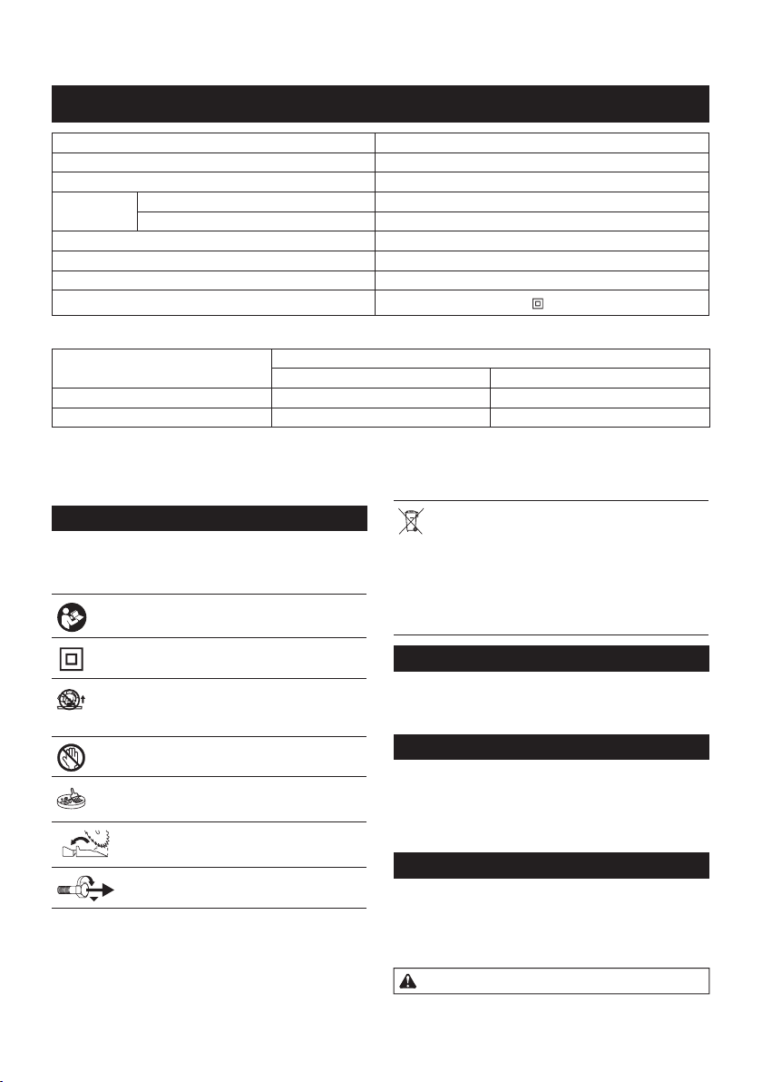
Designation of Machine: Compound Miter Saw
Model No./ Type: M2300
Conforms to the following European Directives:
2006/42/EC
They are manufactured in accordance with the following
standard or standardized documents: EN61029
Thetechnicalleinaccordancewith2006/42/ECis
available from:
Makita, Jan-Baptist Vinkstraat 2, 3070, Belgium
1.1.2016
Yasushi Fukaya
Director
Makita, Jan-Baptist Vinkstraat 2, 3070, Belgium
General power tool safety warnings
WARNING: Read all safety warnings and
all instructions. Failure to follow the warnings and
instructionsmayresultinelectricshock,reand/or
seriousinjury.
Save all warnings and instruc-
tions for future reference.
The term "power tool" in the warnings refers to your
mains-operated (corded) power tool or battery-operated
(cordless) power tool.
MITER SAW SAFETY WARNINGS
1. Keep hands out of path of saw blade. Avoid
contact with any coasting blade. It can still
cause severe injury.
2. Check the saw blade carefully for cracks or
deformation before operation.
Replace damaged blades immediately.
3. Replace the kerf board when worn.
4. Use only saw blades specied by the manufac-
turer which conform to EN847-1.
5. Do not use saw blades manufactured from
high speed steel.
6. Wear eye protection.
7. Wear hearing protection to reduce the risk of
hearing loss.
8. Wear gloves for handling saw blade (saw
blades shall be carried in a holder wherever
practicable) and rough material.
9. Connect miter saws to a dust collecting device
when sawing.
10. Select saw blades in relation to the material to
be cut.
11. Do not use the saw to cut other than wood,
aluminum or similar materials.
12. Always secure all moving portions before car-
rying the tool. When lifting or carrying the tool,
do not use the guard as a carrying handle.
13.
Do not operate saw without guards in place.
Check blade guard for proper closing before
each use. Do not operate saw if blade guard does
not move freely and close instantly. Never clamp
or tie the blade guard into the open position.
14. Keep the oor area free of loose material e.g.
chips and cut-offs.
15. Use only saw blades that are marked with a
maximum speed equal to or higher than the no
load speed marked on the tool.
16. When the tool is tted with a laser or LED, do
not replace the laser or LED with a different
type. Ask an authorized service center for repair.
17. Never remove any cut-offs or other parts of the
workpiece from the cutting area whilst the tool
is running with an unguarded saw blade.
18. Do not perform any operation freehand. The
workpiecemustbesecuredrmlyagainstthe
turn base and guide fence with the vise during all
operations. Never use your hand to secure the
workpiece.
19. Ensure that the tool is stable before each cut.
20. Fix the tool to a work bench, if needed.
21. Support long workpieces with appropriate
additional supports.
22. Never cut so small workpiece which cannot be
securely held by the vise. Improperly held work-
piece may cause kickback and serious personal
injury.
23. Never reach around saw blade.
24. Turn off tool and wait for saw blade to stop
before moving workpiece or changing
settings.
25. Unplug tool before changing blade or
servicing.
26. Stopper pin which locks the cutter head down
is for carrying and storage purposes only and
not for any cutting operations.
27. Do not use the tool in the presence of amma-
ble liquids or gases. The electrical operation of
thetoolcouldcreateanexplosionandrewhen
exposedtoammableliquidsorgases.
28. Use only anges specied for this tool.
29. Be careful not to damage the arbor, anges
(especially the installing surface) or bolt.
Damage to these parts could result in blade
breakage.
30. Make sure that the turn base is properly
secured so it will not move during operation.
31. For your safety, remove the chips, small
pieces, etc. from the table top before
operation.
32. Avoid cutting nails. Inspect for and remove all
nails from the workpiece before operation.
33. Make sure the shaft lock is released before the
switch is turned on.
34. Be sure that the blade does not contact the
turn base in the lowest position.
35. Hold the handle rmly. Be aware that the saw
moves up or down slightly during start-up and
stopping.
36. Make sure the blade is not contacting the
workpiece before the switch is turned on.

10 ENGLISH
37. Before using the tool on an actual workpiece,
let it run for a while. Watch for vibration or
wobbling that could indicate poor installation
or a poorly balanced blade.
38. Wait until the blade attains full speed before
cutting.
39. Stop operation immediately if you notice any-
thing abnormal.
40. Do not attempt to lock the trigger in the on
position.
41. Be alert at all times, especially during repeti-
tive, monotonous operations. Do not be lulled
into a false sense of security. Blades are
extremely unforgiving.
42. Always use accessories recommended in this
manual. Use of improper accessories such as
abrasive wheels may cause an injury.
43. Take care when slotting.
44. Some dust created from operation contains
chemicals known to cause cancer, birth
defects or other reproductive harm. Some
examples of these chemicals are:
• Lead from lead-based-painted material
and, arsenic and chromium from chemi-
cally-treated lumber.
• Your risk from these exposures varies,
depending on how often you do this
type of work. To reduce your exposure
to these chemicals: work in a well venti-
lated area and work with approved safety
equipment, such as those dust masks
that are specially designed to lter out
microscopic particles.
45. To reduce the emitted noise, always be sure
that the blade is sharp and clean.
46. The operator is adequately trained in the use,
adjustment and operation of the machine.
SAVE THESE INSTRUCTIONS.
WARNING: DO NOT let comfort or familiarity
with product (gained from repeated use) replace
strict adherence to safety rules for the subject
product. MISUSE or failure to follow the safety
rules stated in this instruction manual may cause
serious personal injury.
INSTALLATION
When the tool is shipped, the handle is locked in the
lowered position by the stopper pin. Loosen the bolt
with a wrench provided with the tool and move the saw
head to the right angle. Remove the bolt and secure the
saw head with the knob.
►Fig.1: 1. Wrench
►Fig.2: 1. Knob
Installing auxiliary plate
Installing the auxiliary plate using the hole in the tool's
base and secure it by tightening the screw.
►Fig.3: 1. Auxiliary plate 2. Screw 3. Base
Bench mounting
When the tool is shipped, the handle is locked in the
lowered position by the stopper pin. Release the stop-
per pin by lowering the handle slightly and pulling the
stopper pin.
►Fig.4: 1. Stopper pin
This tool should be bolted with four bolts to a level and
stable surface using the bolt holes provided in the tool's
base.Thiswillhelppreventtippingandpossibleinjury.
►Fig.5: 1. Bolt
FUNCTIONAL
DESCRIPTION
CAUTION: Always be sure that the tool is
switched off and unplugged before adjusting or
checking function on the tool.
Blade guard
►Fig.6: 1. Blade guard
When lowering the handle, the blade guard rises auto-
matically. The guard is spring loaded so it returns to
its original position when the cut is completed and the
handle is raised. NEVER DEFEAT OR REMOVE THE
BLADE GUARD OR THE SPRING WHICH ATTACHES
TO THE GUARD.
In the interest of your personal safety, always maintain
the blade guard in good condition. Any irregular opera-
tion of the blade guard should be corrected immediately.
Check to assure spring loaded return action of guard.
NEVER USE THE TOOL IF THE BLADE GUARD OR
SPRING IS DAMAGED, FAULTY OR REMOVED.
DOING SO IS HIGHLY DANGEROUS AND CAN
CAUSE SERIOUS PERSONAL INJURY.
If the see-through blade guard becomes dirty, or saw-
dust adheres to it in such a way that the blade and/or
workpiece is no longer easily visible, unplug the saw
and clean the guard carefully with a damp cloth. Do not
use solvents or any petroleum-based cleaners on the
plastic guard.
If the blade guard is especially dirty and vision through
the guard is impaired, use the supplied wrench to
loosen the hex bolt holding the center cover. Loosen
the hex bolt by turning it counterclockwise and raise
the blade guard and center cover. With the blade guard
so positioned, cleaning can be more completely and
efcientlyaccomplished.Whencleaningiscomplete,
reverse procedure above and secure bolt. Do not
remove spring holding blade guard. If guard becomes
discolored through age or UV light exposure, contact
a Makita service center for a new guard. DO NOT
DEFEAT OR REMOVE GUARD.
►Fig.7: 1. Blade guard

11 ENGLISH
Kerf board
This tool is provided with the kerf board in the turn base
to minimize tearing on the exit side of a cut. If the kerf
groove has not yet been cut in the kerf board by the
factory, you should cut the groove before actually using
the tool to cut a workpiece. Switch on the tool and lower
the blade gently to cut a groove in the kerf board.
►Fig.8: 1. Kerf board
Maintaining maximum cutting
capacity
Thistoolisfactoryadjustedtoprovidethemaximum
cutting capacity for a 255 mm saw blade.
When installing a new blade, always check the lower
limitpositionofthebladeandifnecessary,adjustitas
follows:
First, unplug the tool. Lower the handle completely. Use
thewrenchtoturntheadjustingboltuntiltheperiphery
of the blade extends slightly below the top surface of
the turn base at the point where the front face of the
guide fence meets the top surface of the turn base.
►Fig.9: 1.Adjustingbolt
With the tool unplugged, rotate the blade by hand while
holding the handle all the way down to be sure that
the blade does not contact any part of the lower base.
Re-adjustslightly,ifnecessary.
►Fig.10: 1. Top surface of turn base 2. Periphery of
blade 3. Guide fence
CAUTION: After installing a new blade,
always be sure that the blade does not contact
any part of the lower base when the handle is
lowered completely. Always do this with the tool
unplugged.
Adjusting the miter angle
►Fig.11: 1. Lock lever 2. Grip
Loosen the grip by turning counterclockwise. Turn the
turn base while pressing down the lock lever. When you
have moved the grip to the position where the pointer
points to the desired angle on the miter scale, securely
tighten the grip clockwise.
CAUTION: When turning the turn base, be
sure to raise the handle fully.
CAUTION: After changing the miter angle,
always secure the turn base by tightening the grip
rmly.
Adjusting the bevel angle
►Fig.12: 1. Knob
Toadjustthebevelangle,loosentheknobattherearof
the tool counterclockwise.
►Fig.13: 1. Pointer
Push the handle to the left to tilt the saw blade until the
pointer points to the desired angle on the bevel scale.
Thentightentheknobclockwisermlytosecurethe
arm.
CAUTION: When tilting the saw blade, be sure
to raise the handle fully.
CAUTION: After changing the bevel angle,
always secure the arm by tightening the knob
clockwise.
Switch action
WARNING: Before plugging in the tool,
always check to see that the switch trigger actu-
ates properly and returns to the "OFF" position
when released. Operating a tool with a switch that
does not actuate properly can lead to loss of control
andseriouspersonalinjury.
WARNING: NEVER use tool without a fully
operative switch trigger. Any tool with an inoper-
ative switch is HIGHLY DANGEROUS and must be
repaired before further usage or serious personal
injurymayoccur.
For European countries
►Fig.14: 1. Lever 2. Switch trigger
To start the tool, push the lever to the right and then pull
the switch trigger. Release the switch trigger to stop.
For all countries other than European
countries
►Fig.15: 1. Switch trigger
To start the tool, simply pull the switch trigger. Release
the switch trigger to stop.
ASSEMBLY
CAUTION: Always be sure that the tool is
switched off and unplugged before carrying out
any work on the tool.
Installing or removing saw blade
CAUTION: Always be sure that the tool is
switched off and unplugged before installing or
removing the blade.
CAUTION: Use only the Makita wrench pro-
vided to install or remove the blade. Failure to
do so may result in overtightening or insufcient
tightening of the hex bolt. This could cause an
injury.
When removing or installing the blade, keep the handle
in the raised position.
To remove the blade, use the wrench to loosen the hex
bolt holding the center cover by turning it counterclock-
wise. Raise the blade guard and center cover.
►Fig.16: 1. Wrench 2. Center cover
►Fig.17: 1. Hex bolt

12 ENGLISH
Press the shaft lock to lock the spindle and use the
wrench to loosen the hex bolt clockwise. Then remove
thehexbolt,outerangeandblade.
►Fig.18: 1. Hex bolt 2. Wrench
To install the blade, mount it carefully onto the spindle,
making sure that the direction of the arrow on the sur-
face of the blade matches the direction of the arrow on
the blade case.
►Fig.19: 1. Blade case 2. Arrow 3. Arrow 4. Saw
blade
Installtheouterangeandhexbolt,andthenusethe
wrench to tighten the hex bolt (left-handed) securely
counterclockwise while pressing the shaft lock.
►Fig.20: 1. Spindle 2. Flange 3. Saw blade 4. Flange
5. Hex bolt 6. Ring
CAUTION: The ring 25.4 mm or 30 mm in
outer diameter is factory-installed onto the spin-
dle. Before mounting the blade onto the spindle,
always be sure that the correct ring for the arbor
hole of the blade you intend to use is installed
onto the spindle.
Return the blade guard and center cover to its original
position. Then tighten the hex bolt clockwise to secure
the center cover. Lower the handle to make sure that
the blade guard moves properly. Make sure shaft lock
has released spindle before making cut.
Sub-fence
For European countries only
CAUTION: When performing left bevel cuts,
ip the sub-fence outward. Otherwise, it may con-
tact the blade or a part of the tool, and may result in
seriousinjurytotheoperator.
►Fig.21: 1. Sub-fence
This tool is equipped with the sub-fence. Usually posi-
tion the sub-fence inside. However, when performing
leftbevelcuts,ipitoutward.
Dust bag
►Fig.22: 1. Dust bag
►Fig.23: 1. Fastener
The use of the dust bag makes cutting operations clean
anddustcollectioneasy.Toattachthedustbag,tit
onto the dust nozzle.
When the dust bag is about half full, remove the dust
bag from the tool and pull the fastener out. Empty
the dust bag of its contents, tapping it lightly so as to
remove particles adhering to the insides which might
hamper further collection.
NOTE: If you connect a Makita vacuum cleaner to
yoursaw,moreefcientandcleaneroperationscan
be performed.
Securing workpiece
WARNING: It is extremely important to always
secure the workpiece properly and tightly with
the vise. Failure to do so can cause the tool to be
damaged and/or the workpiece to be destroyed.
PERSONAL INJURY MAY ALSO RESULT. Also,
after a cutting operation, DO NOT raise the blade
until the blade has come to a complete stop.
CAUTION: When cutting long workpieces,
use supports that are as high as the top surface
level of the turn base. Do not rely solely on the
vertical vise and/or horizontal vise to secure the
workpiece. Thin material tends to sag. Support
workpiece over its entire length to avoid blade
pinch and possible KICKBACK.
►Fig.24: 1. Support 2. Turn base
Vertical vise
►Fig.25: 1. Vise knob 2. Screw 3. Vise arm 4. Vise
rod
The vertical vise can be installed in two positions on
either the left or right side of the guide fence. Insert the
vise rod into the hole in the guide fence and tighten the
screw to secure the vise rod.
Position the vise arm according to the thickness and
shape of the workpiece and secure the vise arm by
tightening the screw. Make sure that no part of the tool
contacts the vise when lowering the handle all the way.
If some part contacts the vise, re-position the vise.
Presstheworkpieceatagainsttheguidefenceandthe
turn base. Position the workpiece at the desired cutting
positionandsecureitrmlybytighteningtheviseknob.
CAUTION: The workpiece must be secured
rmly against the turn base and guide fence with
the vise during all operations.
OPERATION
►Fig.26
CAUTION: Before use, be sure to release the
handle from the lowered position by pulling the
stopper pin.
CAUTION: Make sure the blade is not con-
tacting the workpiece, etc. before the switch is
turned on.
CAUTION: Do not apply excessive pressure
on the handle when cutting. Too much force may
result in overload of the motor and/or decreased cut-
tingefciency.Pressdownhandlewithonlyasmuch
force as necessary for smooth cutting and without
signicantdecreaseinbladespeed.
CAUTION: Gently press down the handle
to perform the cut. If the handle is pressed down
with force or if lateral force is applied, the blade may
vibrate and leave a mark (saw mark) in the workpiece
and the precision of the cut may be impaired.

13 ENGLISH
Press cutting
►Fig.27: 1. Vertical vise
Secure the workpiece with the vise. Switch on the tool
without the blade making any contact and wait until the
blade attains full speed before lowering. Then gently
lower the handle to the fully lowered position to cut the
workpiece. When the cut is completed, switch off the
tool and WAIT UNTIL THE BLADE HAS COME TO A
COMPLETE STOP before returning the blade to its fully
elevated position.
Miter cutting
Refertothepreviouslycovered"Adjustingthemiter
angle".
Bevel cut
►Fig.28
Loosen the knob and tilt the saw blade to set the bevel
angle(Refertothepreviouslycovered"Adjustingthe
bevelangle").Besuretoretightentheknobrmlyto
secure the selected bevel angle safely. Secure the
workpiece with a vise. Switch on the tool without the
blade making any contact and wait until the blade
attains full speed. Then gently lower the handle to the
fully lowered position while applying pressure in parallel
with the blade. When the cut is completed, switch off the
tool and WAIT UNTIL THE BLADE HAS COME TO A
COMPLETE STOP before returning the blade to its fully
elevated position.
CAUTION: Always be sure that the blade will
move down to bevel direction during a bevel cut.
Keep hands out of path of saw blade.
CAUTION: During a bevel cut, it may create
a condition whereby the piece cut off will come
to rest against the side of the blade. If the blade is
raised while the blade is still rotating, this piece may
be caught by the blade, causing fragments to be scat-
tered which is dangerous. The blade should be raised
ONLY after the blade has come to a complete stop.
CAUTION: When pressing the handle down,
apply pressure parallel to the blade. If the pressure
is not parallel to the blade during a cut, the angle of
the blade might be shifted and the precision of the cut
will be impaired.
CAUTION: (Only for tools with sub-fence)
Always set the sub-fence outside when perform-
ing left bevel cuts.
Compound cutting
Compound cutting is the process in which a bevel
angle is made at the same time in which a miter angle
is being cut on a workpiece. Compound cutting can be
performed at the angle shown in the table.
Bevel angle Miter angle
45° Left and Right 0° - 45°
When performing compound cutting, refer to “Press
cutting”, “Miter cutting” and “Bevel cut” explanations.
Cutting crown and cove moldings
Crown and cove moldings can be cut on a compound
mitersawwiththemoldingslaidatontheturnbase.
There are two common types of crown moldings and
one type of cove moldings; 52/38° wall angle crown
molding, 45° wall angle crown molding and 45° wall
angle cove molding.
►Fig.29: 1. 52/38° type crown molding 2. 45° type
crown molding 3. 45° type cove molding
Therearecrownandcovemoldingjointswhichare
madetot"Inside"90°corners((a)and(b)inthegure)
and"Outside"90°corners((c)and(d)inthegure.)
►Fig.30: 1. Inside corner 2. Outside corner
►Fig.31: 1. Inside corner 2. Outside corner
Measuring
Measurethewallwidth,andadjustthewidthofthe
workpiece according to it. Always make sure that width
of the workpiece's wall contact edge is the same as wall
length.
►Fig.32: 1. Workpiece 2. Wall width 3. Width of the
workpiece 4. Wall contact edge
Always use several pieces for test cuts to check the
saw angles.
When cutting crown and cove moldings, set the bevel
angle and miter angle as indicated in the table (A) and
position the moldings on the top surface of the saw
base as indicated in the table (B).
In the case of left bevel cut
►Fig.33: 1. Inside corner 2. Outside corner
Table (A)
–Molding
position
in the
gure
Bevel angle Miter angle
52/38°
type
45° type 52/38°
type
45° type
For
inside
corner
(a) Left
33.9°
Left 30° Right
31.6°
Right
35.3°
(b) Left
31.6°
Left
35.3°
For
outside
corner
(c)
(d) Right
31.6°
Right
35.3°
Table (B)
–Molding
position in
the gure
Molding
edge against
guide fence
Finished
piece
For inside
corner
(a) Ceiling
contact
edge should
be against
gxuide fence.
Finished
piece will be
on the Left
side of blade.
(b) Wall contact
edge should
be against
guide fence.
For outside
corner
(c) Finished
piece will be
on the Right
side of blade.(d) Ceiling
contact edge
should be
against guide
fence.

14 ENGLISH
Example:
In the case of cutting 52/38° type crown molding for
position(a)intheabovegure:
• Tilt and secure bevel angle setting to 33.9° LEFT.
• Adjustandsecuremiteranglesettingto31.6°
RIGHT.
• Lay crown molding with its broad back (hidden)
surface down on the turn base with its CEILING
CONTACT EDGE against the guide fence on the
saw.
• Thenishedpiecetobeusedwillalwaysbeon
the LEFT side of the blade after the cut has been
made.
Cutting aluminum extrusion
►Fig.34: 1. Vise 2. Spacer block 3. Guide fence
4. Aluminum extrusion 5. Spacer block
When securing aluminum extrusions, use spacer blocks
orpiecesofscrapasshownintheguretoprevent
deformation of the aluminum. Use a cutting lubricant
when cutting the aluminum extrusion to prevent build-up
of the aluminum material on the blade.
CAUTION: Never attempt to cut thick or round
aluminum extrusions. Thick aluminum extrusions
may come loose during operation and round alumi-
numextrusionscannotbesecuredrmlywiththis
tool.
Wood facing
WARNING: Use screws to attach the wood
facing to the guide fence. The screws should be
installed so that the screw heads are below the
surface of the wood facing so that they will not
interfere with the positioning of the material being
cut. Misalignment of the material being cut can case
unexpected movement during the cutting operation
which may result in a loss of control and serious
personalinjury.
CAUTION: Use the straight wood of even
thickness as the wood facing.
Use of wood facing helps to assure splinter-free cuts
in workpieces. Attach a wood facing to the guide fence
using the holes in the guide fence.
Seethegureconcerningthedimensionsforasug-
gested wood facing.
►Fig.35: 1. Holes
NOTICE: When the wood facing is attached, do
not turn the turn base with the handle lowered.
The blade and/or the wood facing will be damaged.
NOTE: The maximum cutting width will be smaller by
the width of wood facing.
Cutting repetitive lengths
When cutting several pieces of stock to the same
length, ranging from 240 mm to 380 mm, use the set
plate (optional accessory). Install the set plate on the
holder(optionalaccessory)asshowninthegure.
►Fig.36: 1. Set plate 2. Holder 3. Screw
Align the cutting line on your workpiece with either the
left or right side of the groove in the kerf board, and
whileholdingtheworkpiece,movethesetplateush
against the end of the workpiece. Then secure the set
plate with the screw.
When the set plate is not used, loosen the screw and
turn the set plate out of the way.
NOTE: Use of the holder-rod assembly (optional
accessory) allows cutting repetitive lengths up to
2,200 mm approximately.
Carrying tool
►Fig.37: 1. Stopper pin
Make sure that the tool is unplugged. Secure the blade
at 0° bevel angle and the turn base at left miter angle
fully. Lower the handle fully and lock it in the lowered
position by pushing in the stopper pin.
Carrythetoolbycarryinggripasshowninthegure.If
you remove the holders, dust bag, etc., you can carry
the tool more easily.
►Fig.38
CAUTION: Always secure all moving portions
before carrying the tool.
CAUTION: Stopper pin is for carrying and
storage purposes only and not for any cutting
operations.
MAINTENANCE
WARNING: Always be sure that the blade is
sharp and clean for the best and safest perfor-
mance. Attempting a cut with a dull and /or dirty blade
may cause kickback and result in a serious personal
injury.
CAUTION: Always be sure that the tool is
switched off and unplugged before attempting to
perform inspection or maintenance.
NOTICE: Never use gasoline, benzine, thinner,
alcohol or the like. Discoloration, deformation or
cracks may result.
Adjusting the cutting angle
Thistooliscarefullyadjustedandalignedatthefactory,
but rough handling may have affected the alignment. If
your tool is not aligned properly, perform the following:
Miter angle
►Fig.39: 1. Hex bolt
Loosen the grip which secures the turn base. Turn the
turn base so that the pointer points to 0° on the miter
scale. Tighten the grip and loosen the hex bolts secur-
ing the guide fence using the wrench. If the pointer
does not point to 0° on the miter scale, loosen the screw
which secures the pointer and move and secure the
pointer plate so that the pointer points to 0° on the miter
scale.

15 ENGLISH
Lower the handle fully and lock it in the lowered position
by pushing in the stopper pin. Square the side of the
blade with the face of the guide fence using a triangular
rule, try-square, etc. Then securely tighten the hex bolts
on the guide fence in the order from the right side.
►Fig.40: 1. Triangular rule
Bevel angle
0° bevel angle
►Fig.41: 1.0°bevelangleadjustingbolt
Lower the handle fully and lock it in the lowered position
by pushing in the stopper pin.
Loosen the knob at the rear of the tool.
Loosenthehexnutandturnthe0°bevelangleadjust-
ing bolt on the right side of the turn base two or three
revolutions clockwise to tilt the blade to the right.
Carefully square the side of the blade with the top sur-
face of the turn base using the triangular rule, try-square,
etc.byturningthe0°bevelangleadjustingboltcoun-
terclockwise. Then tighten the hex nut to secure the 0°
bevelangleadjustingboltandtightentheknobsecurely.
Make sure that the pointer on the arm points to 0° on
the bevel scale. If it does not point to 0° on the bevel
scale, loosen the screw which secures the pointer and
move and secure the pointer plate so that the pointer
points to 0° on the bevel scale.
►Fig.42: 1. Triangular rule 2. Saw blade 3. Top sur-
face of turn base
►Fig.43: 1. Pointer
45° bevel angle
►Fig.44: 1.45°bevelangleadjustingbolt2. Pointer
Adjustthe45°bevelangleonlyafterperforming0°
bevelangleadjustment.
Toadjustleft45°bevelangle,loosentheknobandtilt
the blade to the left fully.
Make sure that the pointer on the arm points to 45° on
the bevel scale on the arm.
Ifthepointerdoesnotpointto45°,turnthe45°bevelangleadjust-
ing bolt on the left side of the arm until the pointer points to 45°.
Replacing carbon brushes
►Fig.45
Remove and check the carbon brushes regularly. Replace when
they wear down to 3 mm in length. Keep the carbon brushes
clean and free to slip in the holders. Both carbon brushes should
be replaced at the same time. Use only identical carbon brushes.
Use a screwdriver to remove the brush holder caps.
Take out the worn carbon brushes, insert the new ones
and secure the brush holder caps.
►Fig.46: 1. Brush holder cap 2. Screwdriver
After use
After use, wipe off chips and dust adhering to the tool
with a cloth or the like. Keep the blade guard clean
according to the directions in the previously covered
section titled "Blade guard". Lubricate the sliding por-
tions with machine oil to prevent rust.
To maintain product SAFETY and RELIABILITY,
repairs,anyothermaintenanceoradjustmentshould
be performed by Makita Authorized or Factory Service
Centers, always using Makita replacement parts.

16 FRANÇAIS
FRANÇAIS (Instructions originales)
SPÉCIFICATIONS
Modèle : M2300
Diamètre de lame 255 mm
Épaisseur du corps de la lame 1,6 mm à 2,4 mm
Diamètred’orice Pour tous les pays autres que les pays européens 25,4 mm
Pour les pays européens 30 mm
Vitesse à vide 4 200 min-1
Dimensions (L x l x H) 610 mm x 485 mm x 515 mm
Poids net 14,7 kg
Catégorie de sécurité /II
Capacités de coupe (H x l) avec une lame de 255 mm de diamètre
Angle de coupe en biseau Angle de coupe d’onglet
0° 45° (gauche et droite)
0° 75 mm x 130 mm 75 mm x 90 mm
45° (gauche) 48 mm x 120 mm 48 mm x 90 mm
• Étantdonnél’évolutionconstantedenotreprogrammederechercheetdedéveloppement,lesspécications
contenuesdanscemanuelsontsujettesàmodicationsanspréavis.
• Lesspécicationspeuventvariersuivantlespays.
• Poids selon la procédure EPTA 01/2003
Symboles
Vous trouverez ci-dessous les symboles utilisés pour
l’appareil.Veillezàcomprendreleursignicationavant
toute utilisation.
Lire le mode d’emploi.
DOUBLE ISOLATION
Pour éviter les blessures provoquées par
lesobjetsprojetés,maintenirlatêtedela
scie en position basse une fois la coupe
terminée,jusqu’àcequelalamesoit
complètementarrêtée.
Ne pas placer les mains ou les doigts près
de la lame.
Pour votre sécurité, retirez copeaux ou
autres fragments de la surface du plateau
avant la mise en route.
PlacertoujoursleGUIDEINFÉRIEUR
sur la position gauche pour les coupes en
biseau à gauche. Le non-respect de cette
consigne peut entraîner de graves bles-
sures pour l’utilisateur.
Pour desserrer le boulon, tournez-le dans
le sens des aiguilles d’une montre.
Uniquement pour les pays de l’Union
européenne
Nepasjeterlesappareilsélectriquesavec
les ordures ménagères ! Conformément
à la directive européenne relative aux
déchets d’équipements électriques et
électroniques ainsi qu’à son application
en conformité avec les lois nationales,
les appareils électriques qui ont atteint la
ndeleurduréedeservicedoiventêtre
collectés séparément et renvoyés à un
établissement de recyclage respectueux
de l’environnement.
Utilisation prévue
L’outil est conçu pour effectuer des coupes rectilignes
et des coupes d’onglet dans le bois, avec précision.
Alimentation
L’outilnedevraêtreraccordéqu’àunealimentation
delamêmetensionquecellequiguresurlaplaque
signalétique, et il ne pourra fonctionner que sur un
courant secteur monophasé. Réalisé avec une double
isolation,ilpeutdecefaitêtrealimentéparuneprise
sans mise à la terre.
Bruit
Niveau de bruit pondéré A typique, déterminé selon
EN61029 :
Niveau de pression sonore (LpA) : 92 dB (A)
Niveau de puissance sonore (LWA ) : 105 dB (A)
Incertitude (K) : 3 dB (A)

17 FRANÇAIS
AVERTISSEMENT : Portez un serre-tête
antibruit.
Déclaration de conformité CE
Pour les pays européens uniquement
Makita déclare que la ou les machines suivantes :
Désignation de la machine : Scie à Coupe d’Onglet
N° de modèle/Type : M2300
sont conformes aux Directives européennes suivantes :
2006/42/CE
et sont fabriquées conformément aux normes ou aux
documents normalisés suivants : EN61029
La documentation technique conforme à la norme
2006/42/CE est disponible auprès de :
Makita, Jan-Baptist Vinkstraat 2, 3070, Belgique
1.1.2016
Yasushi Fukaya
Directeur
Makita, Jan-Baptist Vinkstraat 2, 3070, Belgique
Consignes de sécurité générales
pour outils électriques
AVERTISSEMENT : Lisez toutes les
consignes de sécurité et toutes les instructions. Il
y a risque d’électrocution, d’incendie et/ou de graves
blessures si les mises en garde et les instructions ne
sont pas respectées.
Conservez toutes les mises en
garde et instructions pour réfé-
rence ultérieure.
Le terme « outil électrique » dans les avertissements
fait référence à l’outil électrique alimenté par le secteur
(avec cordon d’alimentation) ou à l’outil électrique fonc-
tionnant sur batterie (sans cordon d’alimentation).
CONSIGNES DE SÉCURITÉ POUR
SCIE À ONGLET
1. Gardez bien les mains à l’écart de la lame
de scie. Évitez tout contact avec une lame
« en roue libre ». Vous pourriez vous blesser
gravement.
2. Avant utilisation, assurez-vous que la lame de
scie n’est pas ssurée ni déformée.
Remplacez immédiatement une lame
endommagée.
3. Remplacez le plateau de découpe quand il est
usé.
4. Utilisez uniquement les lames de scie spéci-
ées par le fabricant et conformes à la norme
EN847-1.
5. N’utilisez pas de lames de scie fabriquées en
acier à coupe rapide.
6. Portez une protection oculaire.
7. Portez des protecteurs d’oreilles an de
réduire les risques de perte d’audition.
8. Portez des gants pour manipuler la lame de
scie (les lames de scie doivent être transpor-
tées dans un étui, lorsque possible) et les
matériaux bruts.
9. Raccordez les scies radiales à un dispositif de
collecte de la poussière quand vous sciez.
10. Sélectionnez les lames de scie en fonction du
matériau à couper.
11. N’utilisez pas la scie pour couper autre chose
que du bois, de l’aluminium ou des matériaux
similaires.
12. Immobilisez toujours toutes les pièces mobiles
de l’outil avant de le transporter. Lorsque vous
soulevez ou portez l’outil, n’utilisez pas le
protecteur comme poignée.
13. N’utilisez jamais la scie sans les protecteurs
en place. Vériez le bon fonctionnement du
protecteur de lame avant chaque utilisation.
N’utilisez pas la scie si le protecteur de lame
ne se déplace pas librement et ne se referme
pas instantanément. N’immobilisez jamais le
protecteur de lame en position ouverte.
14. Le sol doit rester exempt de matériaux en vrac,
comme les copeaux et les chutes.
15.
Utilisez uniquement des lames de scie sur les-
quelles est indiquée une vitesse maximale égale
ou supérieure à la vitesse à vide gurant sur l’outil.
16. Lorsque l’outil est équipé d’un laser ou d’une
DEL, ne les remplacez pas par un laser ou une
DEL de type différent. Ces réparations doivent
êtreeffectuéesparuncentred’entretienagréé.
17. N’enlevez jamais de la zone de coupe les
chutes ou autres parties détachées de la pièce
pendant que l’outil fonctionne avec une lame
de scie sans protection.
18.
N’exécutez aucune opération à la volée. La pièce
doitêtrexéefermementsurlesoclerotatifetle
guide avec l’étau pendant toutes les opérations. Ne
maintenezjamaislapièceenplaceaveclamain.
19. Assurez-vous que l’outil est stable avant
chaque coupe.
20. Fixez l’outil sur un établi si nécessaire.
21. Utilisez des cales supplémentaires adaptées
pour soutenir les pièces de grande longueur.
22.
Ne coupez jamais de petites pièces qu’il est
impossible d’immobiliser avec l’étau. Une pièce
mal immobilisée risque d’entraîner des chocs en
retour et de provoquer de graves blessures.
23. Gardez bien les mains à l’écart de la lame de
scie.
24. Mettez l’outil hors tension et attendez l’arrêt de
la lame de scie avant de déplacer la pièce ou
de modier les réglages.
25. Débranchez l’outil avant de remplacer la lame
ou de procéder à une réparation.
26. La broche d’arrêt qui verrouille en position
basse la tête de fraisage sert à des ns de
transport et de rangement uniquement et pas
pour les opérations de coupe.
27. Ne vous servez pas de votre outil en présence
de gaz ou de liquides inammables. L’utilisation
de cet outil électrique comporte un risque d’explo-
sion et d’incendie en présence de liquides ou gaz
inammables.

18 FRANÇAIS
28. N’utilisez que les asques spéciés pour cet
outil.
29.
Prenez garde de ne pas endommager l’alésage,
les asques (tout particulièrement leur surface
d’installation) ou le boulon. Si ces pièces sont
endommagées, la lame peut se casser.
30. Assurez-vous que le socle rotatif est bien
immobilisé, an qu’il ne risque pas de se
déplacer pendant l’opération.
31. Pour votre sécurité, retirez copeaux ou autres
fragments de la surface du plateau avant la
mise en route.
32. Évitez les clous. Avant de travailler votre
pièce, inspectez-la et retirez-en tous les clous.
33. Assurez-vous que le blocage de l’arbre est
relâché avant de mettre le contact.
34.
Assurez-vous que la lame ne touche pas le socle
rotatif quand elle est abaissée au maximum.
35. Tenez la poignée fermement. N’oubliez pas
que la scie se déplace légèrement de haut en
bas au démarrage et à l’arrêt.
36. Assurez-vous que la lame ne touche pas la
pièce avant de mettre le contact.
37. Avant d’utiliser l’outil sur la pièce, faites-le
tourner un instant à vide. Vériez que la lame
ne présente ni balourd ni shimmy qui pour-
raient résulter d’un montage incorrect ou d’un
déséquilibre.
38. Avant la coupe, attendez que la lame ait atteint
sa pleine vitesse.
39. Arrêtez immédiatement si vous remarquez
quoi que ce soit d’anormal.
40. Ne tentez pas de bloquer la gâchette sur la
position de marche.
41. Restez vigilant, surtout durant les opérations
répétées et monotones. Ne vous laissez pas
leurrer par un sentiment trompeur de sécurité.
Les lames ne pardonnent pas.
42. N’utilisez que les accessoires recommandés
dans ce manuel. L’utilisation d’accessoires
différents, disques à tronçonner notamment,
peut entraîner des blessures.
43. Faites attention lorsque vous taillez des
encoches.
44. Les poussières dégagées lors de l’utilisation
de l’outil peuvent contenir certains produits
chimiques reconnus comme pouvant causer le
cancer, des anomalies congénitales ou autres
problèmes de reproduction. Parmi ces pro-
duits chimiques gurent notamment :
• Le plomb que contiennent les maté-
riaux recouverts de peinture à base de
plomb, ainsi que l’arsenic et le chrome
provenant du bois de construction traité
chimiquement.
• Les risques encourus varient suivant la
fréquence d’exposition qu’implique votre
travail. Pour réduire votre degré d’exposi-
tion à ces produits chimiques : travaillez
dans une aire de travail bien aérée et
en utilisant des dispositifs de sécurité
approuvés, comme des masques à pous-
sière spécialement conçus pour ltrer les
particules microscopiques.
45. Pour réduire le bruit émis, assurez-vous tou-
jours que la lame est bien affûtée et propre.
46. L’utilisateur doit avoir reçu une formation
adéquate concernant l’utilisation, le réglage et
le fonctionnement de l’outil.
CONSERVEZ CES
INSTRUCTIONS.
AVERTISSEMENT : NE vous laissez PAS
tromper (au l d’une utilisation répétée) par un
sentiment d’aisance et de familiarité avec le
produit, en négligeant le respect rigoureux des
consignes de sécurité qui accompagnent le pro-
duit en question. La MAUVAISE UTILISATION de
l’outil ou l’ignorance des consignes de sécurité
indiquées dans ce mode d’emploi peut entraîner
de graves blessures.
INSTALLATION
À la sortie d’usine, la poignée est verrouillée en position
abaisséeaumoyendelabroched’arrêt.Desserrezle
boulonaveclacléfournieavecl’outiletdéplacezlatête
desciesurlebonangle.Retirezleboulonetxezla
têtedescieaveclepommeau.
►Fig.1: 1. Clé
►Fig.2: 1. Pommeau
Installation de la plaque auxiliaire
Installezlaplaqueauxiliaireaumoyendel’oricesur
le socle de l’outil et maintenez-la en place en serrant
la vis.
►Fig.3: 1. Plaque auxiliaire 2. Vis 3. Socle
Montage sur établi
À la sortie d’usine, la poignée est verrouillée en position
abaisséeaumoyendelabroched’arrêt.Libérezla
broched’arrêtenabaissantlégèrementlapoignéeeten
tirantsurlabroched’arrêt.
►Fig.4: 1.Broched’arrêt
Cetoutildoitêtreboulonnéavecquatreboulonssurune
surfaceplaneetstableaumoyendesoricespourbou-
lon prévus sur le socle de l’outil. Ceci permettra d’éviter
tout risque de renversement et de blessure.
►Fig.5: 1. Boulon
DESCRIPTION DU
FONCTIONNEMENT
ATTENTION : Assurez-vous toujours que
l’outil est hors tension et débranché avant de
l’ajuster ou de vérier son fonctionnement.

19 FRANÇAIS
Protecteur de lame
►Fig.6: 1. Protecteur de lame
Le protecteur de lame s’élève automatiquement lorsque
vous abaissez la poignée. Le protecteur étant équipé
d’un ressort de rappel, il revient à sa position d’origine
une fois la coupe terminée et la poignée relevée. NE
MODIFIEZ, NI NE RETIREZ LE PROTECTEUR DE
LAME OU SON RESSORT.
Parmesuredesécurité,conserveztoujoursleprotec-
teur de lame en bon état. Un fonctionnement irrégulier
duprotecteurdelamedoitêtrecorrigésur-le-champ.
Vériezquelemécanismederappelparressortdu
protecteur fonctionne correctement. N’UTILISEZ
JAMAIS L’OUTIL SI LE PROTECTEUR DE LAME OU
LE RESSORT EST ENDOMMAGÉ, DÉFECTUEUX
OU RETIRÉ. CECI EST TRÈS DANGEREUX ET PEUT
PROVOQUER DE GRAVES BLESSURES.
Si le protecteur de lame transparent devient sale ou si
la sciure de bois y adhère au point que la lame et/ou la
pièce ne soient plus bien visibles, débranchez la scie et
nettoyez soigneusement le protecteur avec un chiffon
humide. N’utilisez aucun solvant ou nettoyant à base de
pétrole sur le protecteur en plastique.
Si le protecteur de lame est particulièrement sale et
qu’ilestdifciledevoiràtraversleprotecteur,utilisez
la clé fournie pour desserrer le boulon hexagonal main-
tenant le capot central. Desserrez le boulon hexagonal
en le tournant dans le sens inverse des aiguilles d’une
montre et soulevez le protecteur de lame et le capot
central. Avec le protecteur de lame dans cette position,
il est possible de réaliser un nettoyage plus complet
etefcace.Unefoislenettoyageterminé,exécutezla
procédureci-dessusdansl’ordreinverseetxezlebou-
lon. Ne retirez pas le ressort du protecteur de lame. Si
le protecteur se décolore avec le temps ou sous l’effet
des rayons ultraviolets, contactez un centre d’entretien
Makita pour obtenir un protecteur neuf. NE MODIFIEZ
NI NE RETIREZ LE PROTECTEUR.
►Fig.7: 1. Protecteur de lame
Plateau de découpe
Le socle rotatif de cet outil est équipé d’un plateau de
découpe pour minimiser la déchirure du côté de sortie
delacoupe.Siunerainuren’apasdéjàétécoupée
dans le plateau de découpe en usine, il est nécessaire
de couper la rainure avant d’utiliser réellement l’outil
pour couper une pièce. Mettez l’outil sous tension et
abaissez délicatement la lame pour couper une rainure
dans le plateau de découpe.
►Fig.8: 1. Plateau de découpe
Maintien de la capacité de coupe
maximale
Cet outil est réglé en usine pour offrir une capacité de
coupe maximale avec une lame de scie de 255 mm.
Lorsquevousinstallezunelameneuve,vérieztou-
jourslapositionlimiteinférieuredelalame,etréglez-la
comme suit si nécessaire :
Commencez par débrancher l’outil. Abaissez complè-
tement la poignée. Avec la clé, tournez le boulon de
réglagejusqu’àcequelapériphériedelalames’étende
légèrement sous la surface supérieure du socle rotatif
au point où la face avant du guide rencontre la surface
supérieure du socle rotatif.
►Fig.9: 1. Boulon de réglage
Avec l’outil débranché, faites tourner la lame manuel-
lement en maintenant la poignée en position complète-
mentabaissée,and’êtrecertainquelalamen’entre
en contact avec aucune partie du socle inférieur. Au
besoin,effectuezunlégerréajustement.
►Fig.10: 1. Surface supérieure du socle rotatif
2. Périphérie de la lame 3. Guide
ATTENTION : Après avoir installé une lame
neuve, assurez-vous toujours que la lame ne
touche aucune partie du socle inférieur lorsque
la poignée est complètement abaissée. Procédez
toujours alors que l’outil est débranché.
Réglage de l’angle de coupe
d’onglet
►Fig.11: 1. Levier de verrouillage 2. Manche
Desserrez le manche en le tournant dans le sens
inverse des aiguilles d’une montre. Tournez le socle
rotatif tout en maintenant enfoncé le levier de verrouil-
lage. Une fois déplacé le manche sur la position où
l’index pointe sur l’angle souhaité sur le secteur, serrez
fermement le manche dans le sens des aiguilles d’une
montre.
ATTENTION : Lorsque vous tournez le socle
rotatif, veillez à relever complètement la poignée.
ATTENTION : Après avoir modié l’angle de
coupe d’onglet, xez toujours le socle rotatif en
serrant le manche à fond.
Réglage de l’angle de coupe en
biseau
►Fig.12: 1. Pommeau
Pourajusterl’angledecoupeenbiseau,desserrezle
pommeau à l’arrière de l’outil en le tournant dans le
sens inverse des aiguilles d’une montre.
►Fig.13: 1. Index
Poussez la poignée vers la gauche pour incliner la
lamedesciejusqu’àcequel’indexpointeversl’angle
souhaité sur l’échelle. Serrez ensuite fermement le
pommeau dans le sens des aiguilles d’une montre pour
xerlebras.
ATTENTION : Lorsque vous inclinez la lame
de scie, veillez à relever complètement la poignée.
ATTENTION : Après avoir modié l’angle de
coupe en biseau, xez toujours le bras en serrant
le levier vers la droite.

20 FRANÇAIS
Interrupteur
AVERTISSEMENT : Avant de brancher l’outil,
assurez-vous toujours que la gâchette fonctionne
correctement et revient en position d’arrêt une
fois relâchée. L’utilisation d’un outil dont la gâchette
est défectueuse comporte un risque de perte de
contrôle et de graves blessures.
AVERTISSEMENT : N’utilisez JAMAIS un
outil dont le fonctionnement de la gâchette est
défectueux. Tout outil dont la gâchette est défec-
tueuse est EXTRÊMEMENT DANGEREUX et doit
êtreréparéavanttoutenouvelleutilisation,autrement
cela présente un risque de graves blessures.
Pour les pays européens
►Fig.14: 1. Levier 2. Gâchette
Pour démarrer l’outil, poussez le levier vers la droite
puisenclenchezlagâchette.Pourl’arrêter,relâchezla
gâchette.
Pour tous les pays autres que les
pays européens
►Fig.15: 1. Gâchette
Ilsuftd’enclencherlagâchettepourdémarrerl’outil.
Pourl’arrêter,relâchezlagâchette.
ASSEMBLAGE
ATTENTION : Avant d’effectuer toute inter-
vention sur l’outil, assurez-vous toujours qu’il est
hors tension et débranché.
Pose et dépose de la lame de scie
ATTENTION : Avant de poser ou de retirer la
lame, assurez-vous toujours que l’outil est hors
tension et débranché.
ATTENTION : Utilisez exclusivement la clé
Makita fournie pour poser ou retirer la lame.
Sinon, le boulon hexagonal risque d’être trop
ou pas assez serré. Cela peut entraîner des
blessures.
Lors du retrait ou de la pose de la lame, maintenez la
poignée sur la position levée.
Pour retirer la lame, desserrez avec la clé le boulon
hexagonal maintenant le capot central en le tournant
dans le sens inverse des aiguilles d’une montre.
Soulevez le protecteur de lame et le capot central.
►Fig.16: 1. Clé 2. Capot central
►Fig.17: 1. Boulon hexagonal
Appuyez sur le blocage de l’arbre pour verrouiller l’axe
et desserrez avec la clé le boulon hexagonal dans le
sens des aiguilles d’une montre. Retirez ensuite le
boulonhexagonal,leasqueextérieuretlalame.
►Fig.18: 1. Boulon hexagonal 2. Clé
Pourposerlalame,xez-lasoigneusementsurl’axe
envousassurantquelesensdelaèchesurlasur-
facedelalamecorrespondausensdelaèchesurle
porte-lame.
►Fig.19: 1. Porte-lame 2. Flèche 3. Flèche 4. Lame
de scie
Installezleasqueextérieuretleboulonhexagonal,
puis, à l’aide de la clé, serrez à fond le boulon hexa-
gonal(letageàgauche)danslesensinversedes
aiguilles d’une montre tout en appuyant sur le blocage
de l’arbre.
►Fig.20: 1. Axe 2. Flasque 3. Lame de scie
4. Flasque 5. Boulon hexagonal 6. Bague
ATTENTION : La bague de diamètre externe
de 25,4 mm ou 30 mm est installée en usine sur
l’axe. Avant de poser la lame sur l’axe, assu-
rez-vous toujours qu’une bague adéquate pour
l’alésage central de la lame que vous prévoyez
d’utiliser est installée sur l’axe.
Remettez le protecteur de lame et le capot central en
position initiale. Puis serrez le boulon hexagonal dans
lesensdesaiguillesd’unemontrepourxerlecapot
central. Abaissez la poignée pour vous assurer que le
protecteur de lame se déplace adéquatement. Avant
depasseràlacoupe,vériezqueleblocagedel’arbre
n’est pas engagé sur l’axe.
Guide inférieur
Pour les pays européens uniquement
ATTENTION : Tournez le guide inférieur vers
l’extérieur pour les coupes en biseau à gauche.
Sinon, il pourrait entrer en contact avec la lame ou
une autre partie de l’outil, ce qui pourrait entraîner de
graves blessures pour l’utilisateur.
►Fig.21: 1. Guide inférieur
Cet outil est équipé d’un guide inférieur. Le guide
inférieur est habituellement orienté vers l’intérieur.
Tournez-le cependant vers l’extérieur pour les coupes
en biseau à gauche.
Sac à poussière
►Fig.22: 1. Sac à poussière
►Fig.23: 1. Barrette
L’utilisation du sac à poussière garantit une coupe
propre et facilite la collecte de la poussière. Pour
xerlesacàpoussière,insérez-ledansleraccordà
poussières.
Lorsque le sac à poussière est environ à moitié plein,
retirez-le de l’outil et tirez sur la barrette. Videz le sac
à poussière en le tapotant légèrement pour retirer les
particules qui adhèrent à sa surface intérieure et ris-
queraient de faire obstacle à la collecte de la poussière
par la suite.
NOTE : Si vous raccordez un aspirateur Makita sur
votre scie, vous pourrez procéder à des opérations
plusefcacesetpluspropres.
Other manuals for M2300
5
Table of contents
Languages:
Other Makita Saw manuals

Makita
Makita HS7601 User manual

Makita
Makita LS004G User manual

Makita
Makita 5007NH Quick start guide

Makita
Makita 2107F User manual

Makita
Makita SP6000 User manual

Makita
Makita 5008B User manual

Makita
Makita DJV142 User manual

Makita
Makita MLS100 User manual

Makita
Makita UC100DWA User manual

Makita
Makita M5802 Manual
Popular Saw manuals by other brands

US SAWS
US SAWS JS - SERIES operating manual

MULTIQUIP
MULTIQUIP CD6CE13H18 Operation manual

Husqvarna
Husqvarna TS 60 Operator's manual

Milwaukee
Milwaukee 6375-20- 6376-20 Operator's manual

Drill Master
Drill Master Drill Master 6" Cut-Off Saw Owner's manual & safety instructions

Scheppach
Scheppach Wox 700 duo Translation from the original manual