10
For European countries
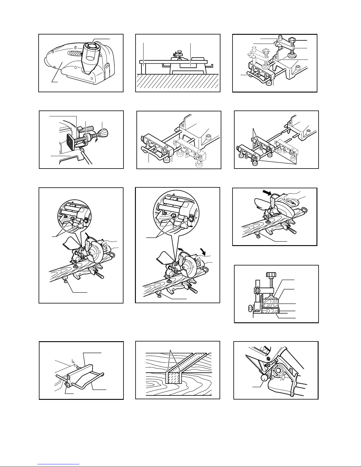
Fig.5
When lowering the handle, the blade guard A rises
automatically. The blade guard B rises as it contacts a
workpiece. The guards are spring loaded so it returns to
its original position when the cut is completed and the
handle is raised. NEVER DEFEAT OR REMOVE THE
BLADE GUARDS OR THE SPRING WHICH
ATTACHES TO THE GUARD.
In the interest of your personal safety, always maintain
each blade guard in good condition. Any irregular
operation of the blade guards should be corrected
immediately. Check to assure spring loaded return
action of guards. NEVER USE THE TOOL IF THE
BLADE GUARDS OR SPRING ARE DAMAGED,
FAULTY OR REMOVED. DOING SO IS HIGHLY
DANGEROUS AND CAN CAUSE SERIOUS
PERSONAL INJURY.
If the see-through blade guard becomes dirty, or
sawdust adheres to it in such a way that the blade is no
longer easily visible, unplug the saw and clean the guard
carefully with a damp cloth. Do not use solvents or any
petroleum-based cleaners on the plastic guard.
If the blade guard is especially dirty and vision through
the guard is impaired, use the supplied socket wrench to
loosen the hex bolt holding the center cover. Loosen the
hex bolt by turning it counterclockwise and raise the
blade guard and center cover. With the blade guard so
positioned, cleaning can be more completely and
efficiently accomplished. When cleaning is complete,
reverse procedure above and secure bolt. Do not
remove spring holding blade guard. If guard becomes
discolored through age or UV light exposure, contact a
Makita service center for a new guard. DO NOT
DEFEAT OR REMOVE GUARD.
Fig.6
Positioning kerf board
Fig.7
Fig.8
This tool is provided with the kerf boards in the turn base
to minimize tearing on the exit side of a cut. The kerf
boards are factory adjusted so that the saw blade does
not contact the kerf boards. Before use, adjust the kerf
boards as follows:
First, unplug the tool. Loosen all the screws (2 each on
left and right) securing the kerf boards. Re-tighten them
only to the extent that the kerf boards can still be easily
moved by hand. Lower the handle fully and push in the
stopper pin to lock the handle in the lowered position.
Loosen two clamp screws which secure the slide poles.
Pull the carriage toward you fully. Adjust the kerf boards
so that the kerf boards just contact the sides of the blade
teeth. Tighten the front screws (do not tighten firmly).
Push the carriage toward the guide fence fully and
adjust the kerf boards so that the kerf boards just contact
the sides of blade teeth. Tighten the rear screws (do not
tighten firmly).
After adjusting the kerf boards, release the stopper pin
and raise the handle. Then tighten all the screws
securely.
CAUTION:
• Before and after changing the bevel angle, always
adjust the kerf boards as described above.
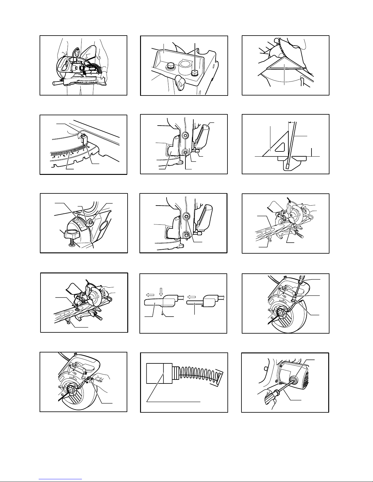
Maintaining maximum cutting capacity
Fig.9
Fig.10
This tool is factory adjusted to provide the maximum
cutting capacity for a 190 mm saw blade.
When installing a new blade, always check the lower
limit position of the blade and if necessary, adjust it as
follows:
First, unplug the tool. Push the carriage toward the guide
fence fully and lower the handle completely. Use the
socket wrench to turn the adjusting bolt until the
periphery of the blade extends slightly below the top
surface of the turn base at the point where the front face
of the guide fence meets the top surface of the turn
base.
With the tool unplugged, rotate the blade by hand while
holding the handle all the way down to be sure that the
blade does not contact any part of the lower base.
Re-adjust slightly, if necessary.
CAUTION:
• After installing a new blade, always be sure that
the blade does not contact any part of the lower
base when the handle is lowered completely.
Always do this with the tool unplugged.
Stopper arm
Fig.11
The lower limit position of the blade can be easily
adjusted with the stopper arm. To adjust it, move the
stopper arm in the direction of the arrow as shown in the
figure. Adjust the adjusting screw so that the blade stops
at the desired position when lowering the handle fully.
Adjusting the miter angle
Fig.12
Loosen the grip by turning counterclockwise. Turn the
turn base while pressing down the lock lever. When you
have moved the grip to the position where the pointer
points to the desired angle on the miter scale, securely
tighten the grip clockwise.
CAUTION:
• When turning the turn base, be sure to raise the
handle fully.
• After changing the miter angle, always secure the
turn base by tightening the grip firmly.