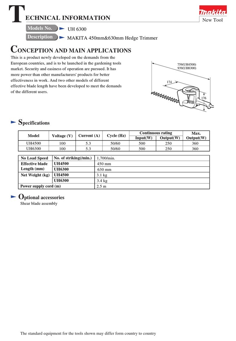
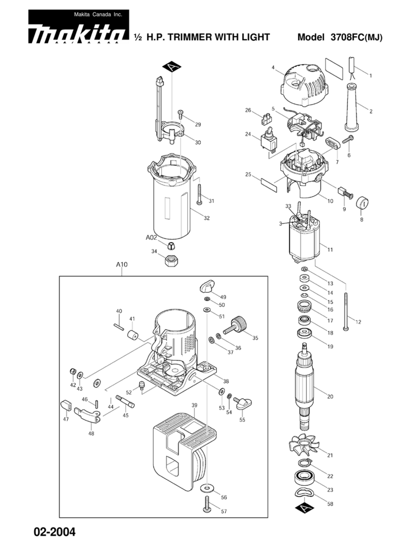
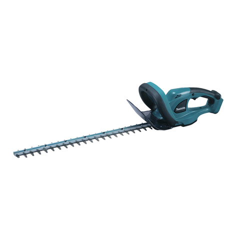
Makita EH561 User manual

MODEL EH561/EH760
SERVICE
MANUAL

1
.
SPECIFICATIONS
a
.
Designation
of
Parts
.....................................................
3
b
.
Specifications
...........................................................
4
2
.
PREPARATIONS
a
.
Disassembly
&
ReassemblyProcedure
......................................
5
b
.
Cautions
..............................................................
6
3
.
DISASSEMBLY
81
ASSEMBLY PROCEDURES
...............................
7
.
9
a
.
Removal
of
Engine and Machine Body
..................................
10
.
11
b
.
Disassembly
&
Assembly of Machine Body
..............................
12
.
13
c
.
Disassembly
&
Assembly
of
Engine
....................................
14
.
18
d
.
Disassembly
&
Assembly
of
Carburetor
.................................
19
.
24
4
.
CHECKUP AND ADJUSTMENT
a
.
Daily Checkupand Adjustment
............................................
25
b
.
Checkup and Adjustment for Every 30
-
50
Hours
.
(Every 10Days)
...............
26
c
.
Checkup and Adjustment for Every
100
-
200 Hours
.
(Monthly)
..................
26
5
.
STANDARD OF ADJUSTMENT
a
.
Tightening Torque of Components
.........................................
27
b
.
StandardAdjustment Table
...............................................
28
c
.
Lubrication Procedure
...................................................
28
d
.
Bladesharpening
.......................................................
28
e
.
BladeAdjustment
.......................................................
29
6
.
TROUBLESHOOTING
.................................................
30
-
31
2

1
SPECIFICATIONS
a. Designation
of
Parts
Fiirl
lank
rap
\
I
o
switrtl
(ON
orr)

b.
Specifications
Dimensions
(L
x
Wx
H)
Mass (with blade cover) kg
mm
I
Model
1,041
x
280
x
258 840
x
246
x
225
5.8 5.8
EH760
Volume (fueltank) cm3
Engine displacement cm3
Cutting length mm
Maximumengineperformance
kw
EH561
600
21.7
735
560
0.74
Clutchengagement speed l/min
Carburetor type type
3,600
WALBRO WYL
I
Maximumblade speed m/s
1
Ignition system type
Spark plug type
Electrodegap mm
I
1.88
Solid ignition system
NGK-BMR7A
0.6
-
0.7
1
Idlingspeed l/min
I
Mixture ratio (fuel: MAKITA 2-strokeoil)
Gear ratio
2,600
50:
1
14
:
58
1) The data takes equally into account idlingand racingspeed operating modes.

2.
PREPARATIONS
a. Disassembly and Reassembly Procedures
The disassembly and reassembly procedures mentioned below are given as a general rule. These
procedurescan be added
to
or omitted accordingto your operating conditions.
II.
PREPARATIONS Cleaning
Drainageof fuel
Disposition
of
tools
I
Ill.
DISASSEMBLY
1.
Machinebody
2
Engine
CHECKUP Cleaning of parts
Checking
of
parts
(Referto
IV.
CHECKUPAND ADJUSTMENT)
(Referto
V.
STANDARDOF ADJUSTMENT)
(Referto
X.
SETTING
OF
BRUSHBLADE)
1
IV.
REASSEMBLY
1.
Engine
2
Machinebody
(Referto
VIII.
TABLE
OF
TIGHTENINGTORQUE)
I
c
I.
STARTINGTEST
1.
Starting procedure
2
Checkupand adjustment of carburetor
Checkupand adjustment
(Referto
IX.
TROUBLESHOOTING)
NOTE: The numbers are the same as those inthis manual.
5

b.
Cautions
1)
Preparations
(1
)
Workbench
(2)
Disassemblyand reassembly kitsand gauges
(3)
Washing bowl
(4)
Rinseoil (lightoil, gasoline, etc.)
(5)
Oil (mobileoil), grease
(6)
Adhesive, sealant
(7)
File, sandpaper
(8)
Shopcloth
2)
Cautions in Disassembly
(1)
Use standardtoolscorrectly.
(2)
Handle disassembled parts with care and be sure to cleanthem.
Inparticular, remove dust or dirt adhering to the mountingsurfaces of packings.
Bearings inrod areeasy to separate.
If
there is no abnormality on rod, no specialmaintenance is
neededwithout removingcontaminated grease.
(3)
Keepdisassembled parts in order to avoid
loss
or error in reassembly.
(4)
If
it is hardto loosen bolts or screws, use an impact driver.
3)
Cautions in Reassembly
(1)
Pay attentionto the combination of parts (in particular, mountingdirection: front and rear, right and
(2)
Replace packings and gasketswith new ones.
(3)
Tighten boltsand screws twice ina diagonal manner.
(4)
Apply two-cycleengine oil (or Mobile oil) to rotary and slidingparts.
(5)
During reassembly,be carefulto keep parts free of dust and dirt.
(6)
For rotating parts, turn them by handto check for movementor noise.
(7)
After reassembly,turnthe rotating parts by hand and confirmthat there is noabnormality (loosen-
(8)
Neverfail to apply genuine grease into case.
left, upper and lower).
ing, etc.)
6

3.
DISASSEMBLY
&
ASSEMBLY PROCEDURES
-
-\
__
/
7

8
I

9

a. Removal'of Engineand Machine
Body
For
EH561
1.
StarVStop leadwire
Remove lead wire connecting rear-handle stop
switch with engine.
2.
Throttlewire
Remove cable holder fixed to rear handle by
loosening screw (M4x
10).
Removethrottlewire from throttle lever parts.
Cable
holder
3.
Engine
Removeengine by loosening
two
bolts (M6 x
15,
PW,
SW)
with fixing case and engine and one bolt (M6 x 40,
W,
SW)
with combine rear handlewith case and engine.
4. Rear handle
Loosen bolt (M6 x
50,
W,
SW)
on case side and
remove rear handle.
5.
Front handle
Loosen bolt (M6 x
35,
SW)
with fixing case and front handle and removefront handle.
10

For
EH760
*
Remove lead wire connecting rear-handle
stop
switch with engine.
1.
StarVStop
lead
wire
2.
Throttlewire
(For
STD)
Removethrottlewire form throttle lever.
(For
CE)
Removethrottlewire from carburetor.
3.
Left handle
Loosening
two
bolts
(M5
x
30)
with handleholder.
4.
Handle holder
Loosen
two
bolts
(M6
x
35,
W,
SW)
with engine.
5.
Engine
Removeengine
by
looseningthree bolts
(M6
x
15,
PW,
SW)
with fixing case and engine.
6.
Right handle
Loosening
two
screws with Bladeand remove right handle.
11

b. Disassembly
4%
Assembly
of
Machine
Body
Crank
qear
Drum
.
\
Upper
case
-
Lower
ca5
Pinion
qear
/
1.
Drum
Lock blade by tightening
3
blade slide screws to
the full. Then remove drum by using drum hole.
If
drum can not be loosened, apply wood chip
under blade nearer at engine and remove drum
by using drum hole.
<Caution>
The screws are right-handed. Turn to the left in
loosening.
Be careful not to misscollar under drum.
2.
Lower case
Remove
3
blade-fixingU-nutsfirst. Then loosen
7
bolts
(5
M5
x
16
and
2
M5
x
20)
and remove lower case.
It is advisableto remove lower case, tapping itwith plastic hammer.
If
it is hardto remove case, pry case with flat-headedscrewdriver payingattention not to damage case or parts
insidecase.
After mounting,temporality tighten
3
blade-fixingUnuts.
(Applyoilto sliding parts inproper amount.)
<Caution:,
This work must be done at a place as low as possible, as there is possibility that needles separate
if
rod is
detached together with case.
Becareful not to damage case contact surfaces.
Apply greaseto rod and gear in properamount.
12

3.
Rod slide plate, Pinion gear, Felt
Loosen
2
screws
(M3
x
5)
and
remove
rod slide
plate
fixed under lower
case.
Then remove piniongear from upper case.
If
it
is hardto remove, tap pinionwith plastic hammer.
Then removefelt.
4.
Rod
Remove rod on lower-bladeside.
<Caution>
Before removing rod, apply a small amount of grease to needles and turn rod several times
so
that they will
not separate.
Keep in memory rod mountingdirection.
Apply grease to crank and lower-blade rod shift and mount rod.
5.
Lower/Upperblade
Loosen
3
blade-slide screws and remove lower blade.
<Caution>
Becareful not to miss blade slide washer.
Then remove upper blade.
6.
Crank gear, Crank
Remove crank gear andcrank from upper case.
If
it is hardto remove, tap case with plastic hammer.
Then loosen screws
(M5
x
10)
fixingcrank gear and crank and remove crank.
<Caution>
Apply greaseto upper case in proper amount.
Apply greaseto crank gear and crank in properquantity and mount them in upper.
7.
Retainer plate, Grease nipple
Loosenflange nut and
2
screws
(M5
x
16)
and remove retainer plate. Then removegrease nipple.

c.
Disassembly
&
Assembly
of
Engine
14

w
-J
m
Q
u
/
/
0
V
-I
0
Z
0
t--
a
i
,/
a:
0
t-
W
3
m
a
cl
u
a
15

1.
Fueltube
Pullfueltube about
20
-
30
mmout side fueltank
for easy assembly.
Assemblefueltube as shown inthe figure.
Return fuel tube to within the tank following
assembly.
(with no bends that might prevent smooth fuel
flow)
2.
Cylinder cover
Keep the muffler gasket and insulator gasket in
the correct positionwhen assemblingthecylinder
cover.
Keepthe cover spacer and washer in the correct
position when assembling the cylinder cover to
the cylinder.
3.
Buffleplate
Assemble buffle plate to blower housing as
shown inthe figure.
Insulator
16

4.
Clutch
Keepthe washer in the correct positionwhen assemblingthe clutch.
5.
Ignitioncoil
Use thickness gauge
to
assure that the air gap will be
0.3
-
0.4
mm betweenthe ignition coil and flywheel
magnet portionwhen installingthe ignitioncoil.
6.
Flywheel
Install the socket head bolt onto the crankshaft
and tighten them securely. Remove the flywheel
with a pulling
tool
as shown inthe figure.
Duringassembly, be sure first that you have the
crankshaft key slot properly aligned with before
installing. Then check the key slot and flywheel
alignment indication.
7.
Crankcase
When assembling the crankcase, cut
off
the
crankcase gasket sticking out from the cylinder
installingsurface.
(Seefigureat right)
8.
Cylinder
cutter
blade
When assemblingthe cylinder, coat boththe cylinder inner surfaceand the pistonitself with 2-cycleengineoil.
17

9.
Piston
When equipping the piston in the crankshaft
ass’y, the triangular mark
(
A
)
on the top of the
positionshould beonthecrankshaft keyslotside.
10.
Piston ring
When installingthe piston ringon the position, alignthe knock pinon the pistonwith the split on the piston ring.
Unlessthey are linedupthe cylinder cannot be assembled.
18

d.
Disassembly
&
Assembly
of
Carburetor
1)
Functionof
Parts
19

(1) Throttle Valve
(2)
Tamper Resistant Plug:
(3) Low-SpeedNeedle:
(4) InletScreen:
(5) NeedleValve:
(6) Fuel Inlet:
(7)
Metering Lever Spring:
(8)
Metering Lever:
(9)
Metering Diaphragm:
(10) MeteringChamber:
(11) Fuel Pump Diaphragm:
(12) FuelOutlet:
(13) Engine Pulse:
(14) MainJet:
(15) Nozzle:
(16) IdleAdjust Screw:
(1
7)
Primer Pump:
(18)
CombinationValve:
(19) Main Check Valve:
(20) Outlet Valve:
(21) InletValve:
Controls engine output.
Preventsentry of air and foreign matter.
Regulatesfuel at idlingor slow rpm.
Filtersfuel intake
to
carburetor.
Controlsfuel supply
to
meteringchamberfrom fuel pump.
Forfuel intake.
Works together with metering diaphragm to ensure constant pressure
in meteringchamber.
Conveys operation of meteringdiaphragmto needlevalve.
Works up or down depending on difference of pressure inside engine
and atmospheric pressure
so
as to open or close the needle valve
through the metering lever and meteringspring.
Suppliesfuel via nozzle by fuel tank.
Undulates,in keepingwith engine pulse. This action serves to send fuel
to the diaphragmchamber.
Allows excessfuel to returnto the tank during primer pump operation.
Takes the negative or positive pressure building up in the crankcase
under piston operation and makes the fuel pump diaphragm work
accordingly.
Regulatesfuel at high speed.
Outlet for fuel sent into the cylinder.
Controls idling rpm.
Bringsfuel up from the fuel tank intothe meteringchamber.
Acts as a check valve betweenprimer pump intakeand charge.
Prevents air in the nozzle from entering the metering chamber when
the primer pump is being worked.
Works just the opposite
of
the inlet valve.
Valve opens when diaphragm is subjected to negative pressure, and
closes under positivepressure, corresponding to the pump action.
20
Other manuals for EH561
1
This manual suits for next models
1
Table of contents
Other Makita Trimmer manuals

Makita
Makita EN400MP User guide

Makita
Makita DUH551 User manual

Makita
Makita UR100D User manual

Makita
Makita DUR141 User manual

Makita
Makita RT001G User manual

Makita
Makita 3707 User manual
Makita
Makita 3711 User manual

Makita
Makita UR006G User manual

Makita
Makita 3708F User manual

Makita
Makita EN4951SH User manual

Makita
Makita UH5580 User manual

Makita
Makita UH4570 User manual

Makita
Makita DUR193 User manual

Makita
Makita M3702 User manual

Makita
Makita EBH252U User guide

Makita
Makita UH007GD201 User manual

Makita
Makita rt0700c User manual

Makita
Makita DUH501 User manual

Makita
Makita 4050, 4850, 5550, 6350 Manual

Makita
Makita DUN461W User manual