Makita HTB7600 User manual

- 1 -
Istruzioni d’impiego (Istruzioni Originali)
Instruction Manual (Original Instructions)
Attenzione:
Osservare attentamente le norme di sicurezza. Errori nell’uso della macchina possono essere causa di incidenti.
Conservare accuratamente le istruzioni d’impiego!
Important:
Read this instruction manual carefully before putting the machine into operation and strictly observe
the safety regulations!
Keep this Instruction Manual!
HTB7600

- 2 -
HTB7600 Lama con denti su un lato HTB7600 Lama con denti su due lati
Le macchine e gli attrezzi sono soggetti ad un continuo sviluppo: ci riserviamo di variare in qualsiasi momento, senza nessun preavviso, i dati, i
pesi, nonchè la costruzione stessa e la dotazione. Non potranno essere vantati diritti su dati ed illustrazioni contenuti nel presente manuale.
The machines and tools are subject to a continuous development. We therefore reserve ourselves the right to vary at any time and without notice weights,
specifications, equipment as well as the construction itself.No claims can be set up to data and drawings contained in this manual.
Peso completo di lame - Overall weight including blades
5,9 kg 6 Kg
Motore - Engine 2 tempi BLUE BIRD - 2 stroke BLUE BIRD
Cilindrata - Displacement
Potenza max. - Max power (6700RPM)
Carburatore - Carburetor A membrane - Diaphragm
Accensione - Ignition system Elettronica - Electronic type
Avviamento - Starting system A strappo con autorecupero - Recoli starter
Tipo frizione - Clutch type Centrifuga automatica - Automatic centrifugal type
Innesto frizione - Friction clutch 3500 rpm
Carburante - Fuel Miscela benzina-olio 50:1 (2%) - Mixture petrol and oil 50:1 (2%)
Capacità serbatoio - Tank capacity 0,5 litri - 0,5 liters
Taglio - Cut
Cespugli e siepi con diametro max. rami 10 mm - Bushes and hedges with 10 mm max branches diameter
Barra tipo - Bar type A doppia lama mobile - Movable double blade
Lunghezza barra - Bar lenght 690 mm
Dimensioni - dimension (LxWxH) 1150 x 270 x 220 mm
Livello di potenza acustica (Lwa) in accordo con 2000/14/EC
Level of sound power (Lwa) as 2000/14/EC
Livello di potenza acustica garantita (Ld) in accordo con
direttiva 2000/14/CE
Level of garanteed sound power (Ld) as directive 2000/14/EC
Livello di vibrazioni in accordo con EN 774
Vibration level as EN 774
MODELLO - MODEL
HTB7600
Denti su un lato
Single side-blade
HTB7600
Denti su due lati
Double side-blade
MAIN PARTS
1 - Starter
2 - Fuel tank
3 - Front handle
4 - Blade
5 - Frame with antivibrating springs
6 - Gear box
7 - Safety trigger
8 - Throttle lever
9 - Rear handle
10- Grip for the handle rotation
11- Stop button
PARTI PRINCIPALI
1 - Impugnatura avviamento
2 - Serbatoio
3 - Impugnatura frontale
4 - Barra
5 - Telaio con antivibranti
6 - Scatola ingranaggi
7 - Grilletto di sicurezza
8 - Leva comando gas
9 - Impugnatura posteriore
10- Grilletto per rotazione impugnatura
11-Interruttore di Stop
3
4
1
2
7
9
8
10 6
5
Tagliasiepi modelli
HTB7600 Single-side blade HTB7600 Double-side blade
Hedgetrimmers model
30,0 c.c. 30,0 c.c.
0,90 Kw 0,90 Kw
101 dB (A)
Incertezza di misura: / Uncertainty of measurement: 2dB (A)
107 dB (A)
4,6 m/s2
Incertezza di misura: / Uncertainty of measurement: 10%
11

- 3 -
* Uso previsto: il tagliasiepi che avete acquistato deve
essere usato esclusivamente per tagliare cespugli
e siepi.
* Leggete attentamente ed accertatevi di comprende-
re tutte le istruzioni ed i consigli esposti in questo
manuale prima d’iniziare ad operare. Dovete conser-
vare per sempre questo manuale e far riferimento ad
esso per ogni problema.
* Deve essere utilizzato solo da persone adulte e ben
istruite sul suo funzionamento da un responsabile
qualificato o dal vostro rivenditore.
* Siete voi operatori i responsabili nei confronti di terzi
e di cose nel raggio d’azione della macchina.
* Non devono esserci nè persone, nè animali o oggetti
danneggiabili entro il raggio di lavoro di 5 metri.
* Lavorate sempre e solo in buone condizioni fisiche,
riposati, senza aver fatto uso di alcool, droghe o far-
maci.
* Lavorate solo in condizioni di buona visibilità e di
luce naturale.
* Usate sempre indumenti di lavoro idonei, e adeguati
strumenti di protezione: tute di lavoro aderenti, scar-
pe pesanti, guanti, casco protettivo etc.
* Indossate sempre occhiali di protezione o visiera,
cuffie antirumore o tappi auricolari.
* Non utilizzate mai organi di taglio differenti da quelli
forniti dalla casa costruttrice, usate solo elementi
originali.
* Non utilizzate mai organi di taglio e utensili rotti o
usurati, deformati, con ammaccature, cricche, incri-
nature.
* Non avviate o tenete in moto il tagliasiepi in ambienti
chiusi.
* Miscelate e maneggiate il combustibile all’aperto,
con motore spento e lontani da ogni fonte di calore,
scintille o fiamme. Durante tali operazioni non fuma-
te.
* Tutti gli interventi di manutenzione, riparazione,
sostituzione di componenti devono essere effettua-
ti sempre a motore spento e con organi di taglio
fermi.
* Tutti i sistemi di sicurezza della macchina, non-
chè l’equipaggiamento di protezione, devono essere
mantenuti operativi durante tutto il periodo di utilizzo
del tagliasiepi.
* Fate attenzione agli effetti delle vibrazioni.
Interrompete spesso il lavoro con brevi pause di
riposo.
* Fate attenzione che lo sminuzzamento di foglie ed
arbusti generano emmissione di aerosol che possono
causare allergie.
*
Appropriate use: the hedgetrimmer purchased by you
must be exclusively used to cut bushes and hedges.
* Read and understand this manual before operating
the unit. Follow all warnings and safety instructions.
Save this manual for future reference.
*
It must only be used by adult persons, properly
instructed by your seller or qualified responsible.
* Operators are responsible against things or third
parties in the action range of the machine.
* Make sure in the work range of 5 meters there are no
persons, animals or objects that could be damaged
or injured.
* While working, make sure you are always in good
physical conditions, rested, not under the effect of
alcohol, drugs or medicines.
* Work must be done just in conditions of good visibility
and natural light.
* Be equipped with proper work cloths and adequate
protection means: tight overalls, strong shoes, glo-
ves, protective helmet etc.
* Protective goggles or face-shield, noise-preventive
cowlings or ear plugs are absolutely necessary.
* Never use cutters which are different from those
ones supplied by the building company; use just ori-
ginal elements.
* Never use broken or worn out cutters, deformed or
presenting dents or cracks.
* Don’t start or run the unit in close rooms.
* Fuel must be mixed and handled in the open, with
stopped engine, away from any source of heat,
flames or sparks. Smoke is forbidden during this
operation.
* Any service, repair, components replacing operation
must be effected with stopped engine and cutters.
* All safety devices of the hedgetrimmer so as the pro-
tection equipment have to be kept operative during
the whole functioning period of the unit.
* Make attention to vibration effects. Work must be
often interrupted, with short rest intervals.
* Caution! Leaves and bushes mincing generate aero-
sol emission which may cause allergya.
SAFETY DIRECTIONS: ATTENTION.
Before starting:
AVVERTENZE PER LA SICUREZZA ATTENZIONE:
Prima di iniziare:

- 4 -
MOREOVER MAKE SURE...
Moreover make sure to be well equipped with
proper cloths and protection means before
starting to work.
In particular:
Clothes: use tight overalls (avoid wearing
large shirts or unbuttoned clothes). Avoid jew-
elry, rings, various objects like ties, scarves
or similar that could be kept by the branches
of the hedges or by the moving parts of the
machine.
Comb your hair so that its length is over the
shoulders.
Wear closed work shoes or high boots with
anti-slip sole allowing you a perfect stability
on the ground (avoid being barefoot, wearing
slippers or open low shoes).
Put on the protection helmet whenever there
is the risk of contact with objects that fall
down during the cleaning of the brushes or
when the brushwoods are at man’s height.
For an efficacious protection of your face
and eyes, the visor and/or the anti-misting
goggles are absolutely necessary: wear them
always!
Protect your hearing too with noise absorb-
ing earphones or auricular plugs. Always use
work gloves resistant to small pushes or cuts
which could be caused above all by the use of
blades, knives or sharp parts.
ASSEMBLY
Before starting to work make sure the follow-
ing parts are well assembled:
a) Place the front handle on the bars, then fix
it by the relative screws/nuts (Fig.1)
b) Make sure clutch drum freely turns when
you accelerate and stays blocked when you
dont accelerate, otherwise adjust the brake
by acting on the relative nuts. (Fig.2-3)
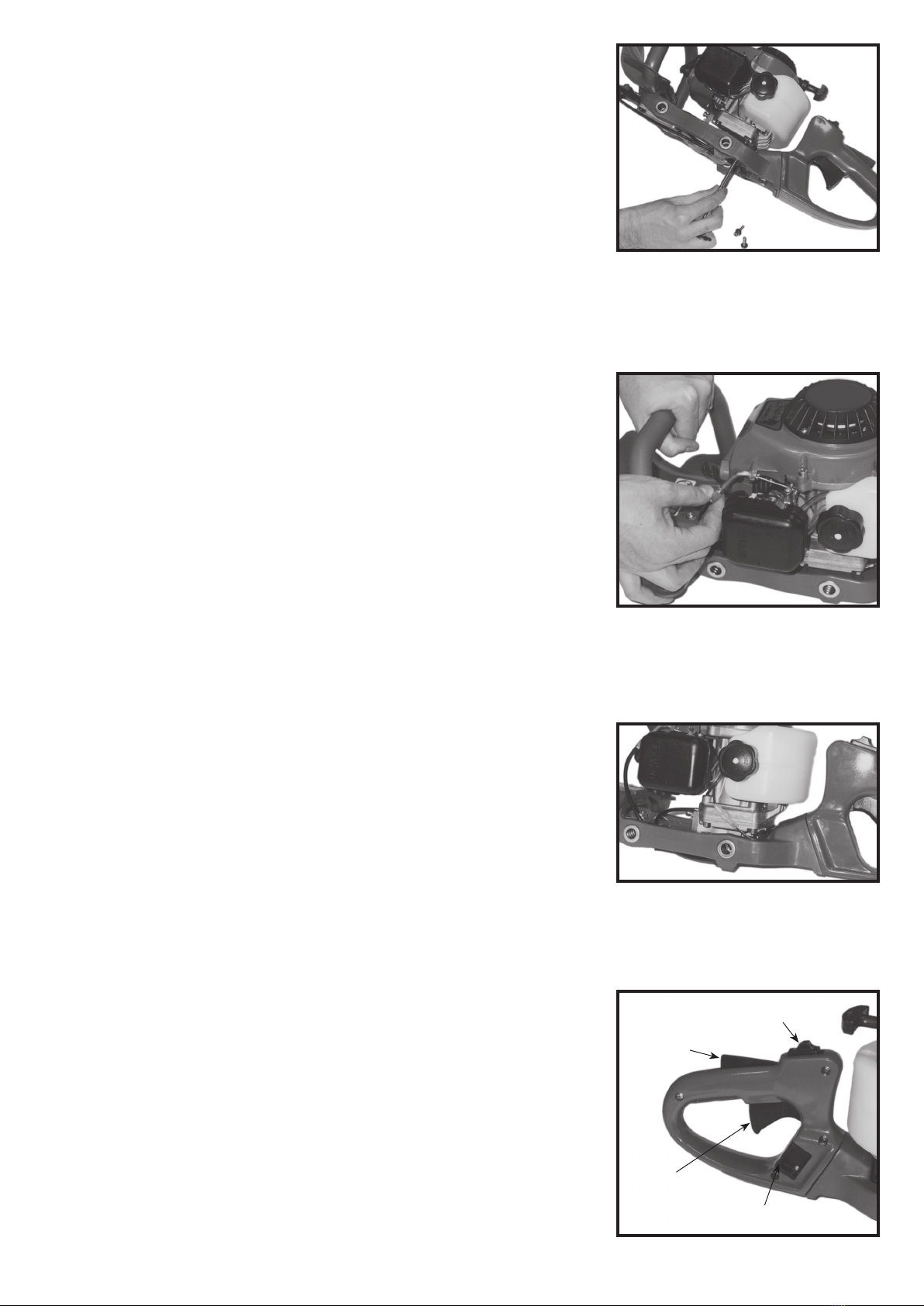
c) Then connect the blades group to the
engine and block by the four screws (Fig.4-
5)
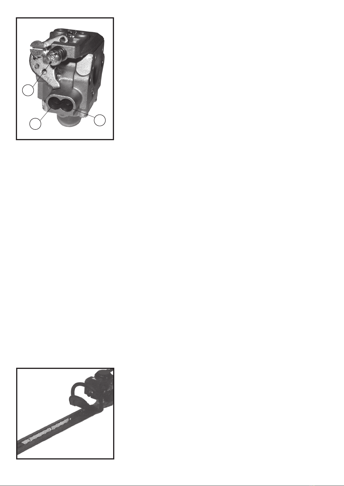
Connection of gas control cable for hed-
getrimmer (fig. 6) The ends of the gas control
cable must be connected to the carburetor by
screwing in the thread bolt.
Now insert the end of the cable in the revolv-
ing pawl of the butterfly valve control.
Adjust the bolt so that you eliminate the pos-
sible clearances between cable and protec-
tive covering in order to obtain a correct and
progressive acceleration.
This bolt is a safety feature and it is used to
keep the machine from an unintentional accel-
eration due to possible holds.
Now connect the eyelet timble of the mass
cable to one of the four clamping screws
which fasten the clutch drum to the engine
and connect the female coupling of the mass
cable to the tap coupling coming out from the
coil (fig. 7).
ASSICURATEVI INOLTRE....
Assicuratevi inoltre di essere bene attrezzati
con idoneo vestiario ed adeguati strumenti di
protezione prima d’iniziare ad operare.
In particolare:
Indumenti: usate tute di lavoro aderenti
(evitate di indossare camicioni o indumenti
slacciati). Evitate gioielli, anelli, oggetti vari
come cravatte, o simili che potrebbero essere
trattenuti dai rami delle siepi o dalle parti in
movimento della macchina.
Acconciatevi i capelli in modo tale che la loro
lunghezza sia sopra la spalla.
Calzate scarpe da lavoro chiuse o stivali alti
dotati di suola antisdrucciolo, che vi consen-
tano una perfetta stabilità sul terreno (evitate
di essere scalzi, d’indossare ciabatte o scarpe
aperte basse).
Mettetevi il casco protettivo ogni qualvolta
esista il rischio di contatto con oggetti che
cadono durante i lavori di pulitura di ramaglie
o in presenza di sterpaglie ad altezza d’uomo.
Sono inoltre indispensabili, per una efficace
protezione del viso e degli occhi, la visie-
ra e/o gli occhiali antiappannanti; portateli
sempre!
Proteggetevi anche l’udito mediante l’uso di
cuffie antirumore o tappi auricolari.
Usate sempre guanti da lavoro resistenti ai
piccoli urti o tagli soprattutto causabili dal
maneggio di lame, coltelli, o parti taglienti.
ASSEMBLAGGIO
Prima d’iniziare a lavorare, assicuratevi che
tutte le parti seguenti siano montate corret-
tamente;
a) Posizionate l’impugnatura frontale sulle
barre: fissatela poi con le relative viti/dadi
(Fig. 1).
b) Assicuratevi che la campana frizione giri
liberamente quando si stà accelerando,
e sia bloccata quando non si sta accele-
rando, in caso contrario regolare il freno
agendo sui relativi dadi (Fig. 2-3).
c) Collegate il gruppo lame al motore e bloc-
cate con le quattro viti (Fig. 4) e bloccate
con le 4 viti (Fig. 5).
Collegamento cavo comando gas: (Fig 6)
L’estremità del cavo comando gas deve essere
collegata al carburatore avvitando il regi-
stro filettato. A questo punto dovete inserire
l’estremità del cavo nel nottolino girevole
comando valvola a farfalla. Regolate ora il
registro in modo da annullare gli eventuali
giochi tra cavo e guaina al fine di avere una
corretta e progressiva accelerazione. Questo
registro è una sicurezza, e impedisce l’ac-
celerazione involontaria o accidentale della
macchina a seguito di eventuali appigli.
Collegate ora il capocorda ad occhiello del
cavo-massa ad una delle quattro viti fissaggio
supporto campana frizione/motore e innestate
il fastom femmina, del cavo massa, al fastom
maschio proveniente dalla bobina. (Fig 7)
Fig. 4
Fig. 3
Fig. 2
Fig. 1

- 5 -
GRILLETTO DI SICUREZZA
SAFETY TRIGGER
CUTTING BLADES
Never use cutting blades supplied by non
Makita authorized dealers/distributors. Tools
which are used must always be in perfect
conditions, i.e. without dents, cracks, defor-
mations, with broken or worn out teeth which
could favour the breaking of the tool. If turned
at very high speed the pieces could become
very dangerous splinters with possible and
serious consequences for persons or things.
Makita will not accept any liability for acci-
dents or damage caused by the use of any non
approved accessories.
ACTIVE SAFETY in the machine
Before starting the machine you should know
that it is equipped with a series of “safeties”:
- Proper protection guards to avoid the con-
tact with all the fiery parts of the machine.
- Nylon or rubber plug cover, so that all elec-
trical parts of the machine having a high
voltage are protected against accidental
contact.
- Anticut system consisting in a blade cover
which avoids the incidental contact with the
blade and particularly with the lower parts of
the body.
- Very large guards and protection barriers.
- Gas control lever with double safety.
- Stop control which allows the easy turning-
off of the engine by a light finger pressure
without having to detach the hand from the
handle (Fig.8).
- Blades brake allowing to block the cutting
blades in a split second as soon as you stop
to accelerate.
CORRECT USE OF THE
ACCELERATOR LEVER (Fig. 8)
For a correct functioning of the lever you
should first know its functions which will
allow you to start the machine and control its
working speed.
a)Acceleration with machine on:
- Grasp the lever pressing the safety trigger.
- Press on the accelerating lever in accor-
dance with the speed you want to use.
b) STOP (turning off):
- Release the lever and the trigger.
- Put the button in position STOP.
To start the machine again it is absolutely
necessary to put the STOP button in the posi-
tion STARTER; the hedgetrimmer can’t start
otherwise, being at mass.
USE OF THE ADJUSTABLE
HANDLE
This hedgetrimmer type mounts a new handle,
adjustable on 5 positions with a 180° rotation
which always allows an optimal cutting posi-
tion (fig. 9).
LAME DI TAGLIO
Non utilizzate lame di taglio differenti da quel-
le fornite da Makita o da un suo rivenditore
autorizzato. Utilizzate sempre lame in perfette
condizioni, prive cioè di ammaccature, incri-
nature, deformazioni, con denti rotti o usurati
che potrebbero favorire la rottura dell’organo,
causando gravi conseguenze all’operatore.
In caso contrario, la casa costruttrice non si
assume nessuna responsabilità per incidenti
o danni causati dall’uso di accessori non
autorizzati.
LA SICUREZZA ATTIVA
della macchina
Prima di avviare la macchina, sappiate che
essa è dotata di una serie di “sicurezze” per
la vostra incolumità:
- ripari di protezione adeguati per impedire
il contatto con tutte le parti roventi della
macchina
- Copricandela in nylon o gomma in modo
che siate protetti da contatti accidentali con
tutte le parti elettriche ad alto voltaggio della
macchina
- Sistema antitaglio composto da un copri-
lama che evita il contatto accidentale con
la lama, in particolare con le parti inferiori
del corpo
- Ripari e barriere di protezione di ampie
dimensioni
- Manopola comando gas con doppia sicu-
rezza
- Comando di stop che con una leggera
pressione delle dita consente di spegnere
facilmente il motore senza essere costretti a
staccare la mano dall’impugnatura (Fig. 8).
- Freno lame che permette di bloccare le lame
di taglio in una frazione di secondo quando
si è smesso di accelerare.
CORRETTO UTILIZZO
DELLA MANOPOLA (Fig. 8)
Per un corretto utilizzo della manopola dovete
innanzitutto conoscerne le funzioni. In questo
modo potrete avviare la macchina corretta-
mente e controllarne la velocità di lavoro.
a) Accelerazione a macchina accesa:
- Impugnate la manopola premendo il grilletto
di sicurezza
- Premete sulla leva acceleratore a seconda
della velocità che volete utilizare.
b) STOP (spegnimento motore):
- Lasciare la presa della leva ed il grilletto
- Portare il pulsante in posizione di STOP.
Per riavviare la macchina è indispensabile
portare il pulsante di STOP nella posizione
STARTER, altrimenti il tagliasiepi non può
partire essendo a massa.
Fig. 8
Fig. 5
Fig. 6
Fig. 7
PULSANTE STOP
STOP BUTTON
LEVA ACC.
ACCELERATOR LEVER
GRILLETTO PER ROTAZIONE IMP.
GRIP FOR THE HANDLE ROTATION

- 6 -
In order to turn the handle pull the grip placed
on the right side of the handle it self (fig. 8)
and at, the same time turn and block it in the
derired position loosening the grip. At this
point you are in measure to start operating
again in an optimal way.
NOTICE
1) Do not swivel the rear handle while you are
operating the engine throttle lever.
2) When swivelling the rear handle, do not
operate the throttle until handle swivel
operation is completed and the handle is
securely locked.
STARTING PREPARATION
Before starting the hedgetrimmer make sure
it is carefully put on a flat and clean surface
without obstacles. Put it in horizontal position
so that the cutting blade do not touch either
the ground or any other object. Make sure all
screws are perfectly tightened. Make sure you
have correctly mounted the guard-handle,the
whole blades group and the engine.
Clean the space to be cut before every work:
take away all objects like stones, wires or
strings that could get caught in the cutting
accessory.
It is not allowed to start the machine inside
closed rooms or buildings: exhaust fumes
breathing can cause poisoning. (Fig.10)
FUEL
The hedgetrimmer works with a standard fuel
mixture made up of 50 parts of petrol and 1
of oil (2%).
The quality of the oil is fundamental. If
you use oil at NMMA TC-W (synthetic oil)
specifications formulated expressly for heav-
ily stressed two stroke engines, mix it to the
percentages indicated on the packaging. This
type of oil reduces the formation of ash and
carbon deposits in the spark-plug, in the cyl-
inder, in the piston and in the muffler, as well
as the emission of exhaust gas.
- The chemical composition of the fuel is
also important; certain components, in fact,
exert aggressive action on the carburetor
diaphragm, gas rings, and manifolds, etc.
For this reason, only qualified brand of petrol
must be used.
Once you have prepared the mixture we sug-
gest you to use it within 3-4 weeks.
Mix the petrol with the oil before
adding it to the tank, and perform
this operation in an open area with
good ventilation far from sparks and
flames and sources of non-electric
light, without smoking, and with the
engine off.
UTILIZZO DELL’IMPUGNATURA
REGOLABILE
Questo tipo di tagliasiepi monta una nuova
impugnatura regolabile su 5 posizioni con una
rotazione di 180° per garantire sempre una
posizione di taglio ottimale (Fig. 9) per poter
ruotare l’impugnatura tirare il grilletto posto
sul lato destro dell’impugnatura stessa (Fig. 8)
e nello stesso tempo ruotarla e bloccarla nella
posizione voluta rilasciando il grilletto.
A questo punto sarete in grado di riprendere il
vostro lavoro in modo ottimale.
AVVERTENZA
1) Non cambiare la posizione dell’impugna-
tura posteriore mentre si aziona la levetta
dell’acceleratore.
2) Durante il cambio di posizione dell’impu-
gnatura posteriore, non azionare l’accele-
ratore finché non si sarà terminata l’opera-
zione e l’impugnatura non sarà saldamente
bloccata in posizione.
PREPARAZIONE AVVIAMENTO
Prima di avviare il tagliasiepi, assicuratevi
che esso sia appoggiato con cura su un fondo
piano, pulito, privo di ostacoli. Ponetelo in
posizione orizzontale ed in modo tale che le
lame non tocchino nè il suolo nè alcun altro
oggetto.
Assicuratevi che tutte le viti siano corretta-
mente serrate.
Assicuratevi di aver montato correttamen-
te l’impugnatura-riparo, il gruppo lame e il
motore.
Pulite la zona di taglio prima di ogni lavoro:
togliete oggetti vari, fili di metallo o spaghi che
potrebbero impigliarsi nelle lame.
Non avviate la macchina all’interno di ambienti
chiusi o edifici: respirare i fumi di scarico può
causare pericolo di intossicazione (Fig. 10).
IL CARBURANTE
-I tagliasiepi funzionano con miscela stan-
dard composta da 50 parti di benzina e 1 di
olio (2%). La qualità dell’olio è fondamentale.
Se usate olio a specifiche NMMA TC-W (olio
sintetico) appositamente studiato per motori
a due tempi fortemente sollecitati, miscelato
nelle percentuali indicate sulla confezione.
Questo tipo di olio riduce la formazione di
ceneri e incrostazioni, nella candela, sul
pistone, nel cilindro e nella marmitta, non-
ché l’emissione di fumi in uscita. È anche
importante la composizione chimica del car-
burante; infatti certi componenti esercitano
un effetto aggressivo sulle membrane del
carburatore, sugli anelli di tenuta, sui collet-
tori. etc...
Si devono quindi impiegare esclusivamente
benzina ed olio di marca qualificata.
Una volta preparata la miscela si consiglia di
utilizzarla entro 3-4 settimane.
Fig. 9
Fig. 10

- 7 -
- Proceed to the filling of the tank by slowly
unscrewing the cap and pouring in the
mixture, being careful to avoid spilling and
immediately wiping up any spills that occur
from around the engine. Be careful not to
spill any mixture on your clothing.
- Start the engine at least three meters away
from the place where the fuel tank was filled
in order to avoidrisk of fire.
- Never fill the fuel tank when the machines
is hot.
ENGINE STARTING
After having carried out all preparation and
refuelling operations, make sure the handle
push button is not on STOP.
Grasp the hedgetrimmer with your left hand
(Fig. 11) and slowly pull the starting cord with
your right hand till the pawls hook on the
handwheel. Following the hereunder specified
instructions regarding the carburetor, firmly
pull the starting cord till the machine starts.
Never pull at stroke end in order not to dam-
age the hooking mechanism.
Your machine is equipped with carry out the
following operations:
1)With cold engine press the priming bulb “1”
(Fig. 12) under the carburetor for 5-6 times
till the mixture comes out the small down-
pipe (completely filling up all the chambers
of the carburetor).
2)Put the air lever (Fig. 14)in position CLOSE,
pull the starting cord from 1-2 times till
you hear the first chugs. Even if you do not
hear them, take back the lever to position
OPEN.
3) Pull again the starting cord till the engine
starts. If the engine does not start after the
fourth pull, repeat the operation as from
point 1.
If after several attempts the engine still doesn’t
start, it means the combustion chamber is
flooded. In this case unscrew and dry the
spark plug and pull the starting cord for some
times without the spark plug in order to clean-
ventilate the combustion chamber.
Miscelate la benzina con l’olio
prima di immetterla nel serbatoio.
Eseguite questa operazione in un
luogo aperto, arieggiato, lontano
da fonti di luce non elettrica, senza
fumare, lontano da scintille, ed a
motore spento.
-Potete ora riempire il serbatoio della macchi-
na: svitare il tappo del serbatoio lentamente
e versate la miscela facendo attenzione di
non rovesciarla fuori, altrimenti asciugate
scrupolosamente il motore. Evitate che i
vostri indumenti si bagnino di miscela.
-Eseguire l’avviamento almeno tre metri lon-
tano dal luogo nel quale avete effettuato il
rifornimento al fine di evitare eventuali peri-
coli d’incendio.
-Non riepire il serbatoio a macchina
calda.
AVVIAMENTO DEL MOTORE
Dopo aver eseguito attententamente tutte
le operazioni di preparazione e rifornimento,
assicurarsi che il pulsante sull’impugnatura
non sia in posizione di STOP.
Impugnate il tagliasiepi con la mano sinistra
(Fig. 11) e con la destra tirate lentamente
la funicella fino all’aggancio dei crichetti sul
volano. Seguendo le istruzioni inerenti al
carburatore, qui sotto specificate, tirate con
decisione la funicella avviamento fino all’ac-
censione della macchina. Non tirare mai a
fine corsa per non danneggiare il meccanismo
di aggancio.
Operate eseguendo le operazioni come qui di
seguito specificato:
1) a motore freddo premete 5-6 volte il bulbo
di adescamento “1“ (Fig. 12) fino alla
fuoriuscita di miscela dall’apposito tubetto
di scarico (in modo da riempire completa-
mente tutte le camere del carburatore)
2) ponete la leva sulla cuffia aria (Fig. 14) in
posizione CLOSE, tirate la funicella avvia-
mento da 1 a 2 volte massimo. Anche se
non si dovessero sentire gli scoppiettii,
riportate la leva sulla cuffia in posizione
OPEN
3) tirate nuovamente la funicella avviamento
fino all’accensione del motore. Se il motore
non parte dopo il quarto strappo ripetere le
operazioni come da punto 1.
Se, malgrado i ripetuti tentativi di avviamento
il motore non parte significa che la camera
di combustione è ingolfata. In questo caso
svitate e asciugate la candela di accensione
e tirate la funicella di avviamento alcune volte
senza candela in modo da pulire-ventilare la
camera di combustione.
Fig. 11
Fig. 12
1

- 8 -
IMPORTANT: when the engine is hot it is
not necessary to carry out the above said
operations. Simply pull the starting cord till
starting.
CUTTING DANGERS
When operating, firmly grasp the hedgetrim-
mer with both hands, never by one sole hand,
keep one hand on the throttle lever which
drives the work controls and the other hand
on the front handle. Never remove hands from
lever and handle as long as blades keep mov-
ing (Fig. 15).
CORRECT USE
The hedgetrimmer is only used to cut grass,
shrubs and bushes with diameter of branches
not over 10 mm.
Pay attention to the use of this machine; when
it is running and proper cautions such as
explained in this manual have not been taken,
serious injuries may be subsequent to.
Always follow the controls sequence such as
indicated. Caution is highly required during
operation!
a) Start the engine such as previously
explained.
b) When the engine is on, let it run at the mini-
mum speed for 2-3 minutes.
c) Accelerate a few times idling but never to
the maximum in order to check if everything
works properly.
d) With cutting blade in stop position, well
visible and always under your control, go
to your work place keeping it under the line
of your waist and far from your body and
make sure there are no persons in a range
of 5 meters (Fig. 16).
Now you can start working: place yourself in a
stable and safe position on your feet.
The mowing of the grass has to be carried
out slowly and you must move laterally step
by step, making hedgetrimmer oscillate from
right to left. In the double-side blade version,
with alternate motion left-right, right-left. If
you unintentionally hit some obstacles of big
dimensions or if the cutting blade gets caught,
block instantly for overload. If grass, vegetable
filaments, barks roll up around it, reduce
the speed to the minimum to disconnect
the clutch. Make sure that the blade, which
proceeds through inertia, has completely
stopped.. Now SWITCH OFF THE ENGINE. Put
the hedgetrimmer on the ground. Check if the
cutting blade has some damages like cracks
or teeth breaks etc. In this case replace it. If
on the contrary the tool is covered with rolled
up material, remove it completely with your
hands protected by working gloves and with
the help of some tool.
All safety devices of the machine and also the
protection equipment must be kept functional
IMPORTANTE: a motore caldo non occorre
fare le operazioni di cui sopra, ma tirate sem-
plicemente la funicella avviamento fino alla
sua partenza.
PERICOLI NEL TAGLIO
Quando utilizzate il tagliasiepi, impugnatelo
sempre saldamente con entrambe le mani.
Mai utilizzare il tagliasiepi con una mano
sola!
Tenete una mano sulla manopola comando
gas che aziona i comandi di lavoro e l’altra
sull’impugnatura anteriore frontale (Fig. 15).
N.B. mai togliere le mani da manopola e impu-
gnatura finchè le lame sono in movimento
CORRETTO UTILIZZO
Il tagliasiepi serve esclusivamente per tagliare
cespugli e siepi con diametro dei rami non
superiore a 10 mm.
Fate attenzione nell’utilizzare questo attrezzo:
quando è in moto, e non avete le opportune
avvertenze come spiegato in questo manuale,
può arrecarvi delle ferite anche gravi.
Seguite sempre la sequenza dei comandi
come indicato. Agite sempre con molta pru-
denza!
a) avviate il motore come precedentemente
spiegato.
b) A motore avviato, lasciatelo funzionare per
2-3 minuti al minimo dei giri.
c) Accelerate alcune volte a vuoto, ma mai al
massimo , per verificare che tutto funzioni
regolarmente.
d) A lame ferme, ben visibili e sempre sotto
il vostro controllo, raggiungete il posto di
lavoro, tenendole sotto il livello della vita,
rivolte verso il basso, lontane dal vostro
corpo ed assicuratevi che non ci siano
persone nel raggio di 5 metri (Fig. 16).
Ora siete pronti per iniziare il lavoro: ponetevi
in una posizione di equilibrio ben stabili e
sicuri sui piedi.
La tosatura della siepe va eseguita lenta-
mente, spostandovi lateralmente passo dopo
passo facendo oscillare il tagliasiepi da destra
a sinistra. Mentre nella versione con denti su
ambedue i lati, con moto alternato sinistra-
destra, destra-sinistra.
Se urtate casualmente qualche ostacolo di
grossa dimensione, oppure se l’utensile di
taglio s’impiglia, o si blocca improvvisamente
per sovraccarico, o se erbe, fili metallici fila-
menti, cortecce, si avvolgono attorno ad esso,
riducete la velocità al minimo per disinnestare
la frizione e assicuratevi che la lama si sia
arrestata.
Fig. 14
Fig. 15
Fig. 16

- 9 -
during all the period of use of the hedgetrim-
mer.
The hedgetrimmer transmits to the operator
some vibrations caused by the functioning of
the monocylindric stroke engine and of the
other moving parts. They can make the opera-
tor overtire himself and it is therefore advised
to alternate working and resting moments.
The machine is equipped with antivibration
systems made of rubber and designed to get
round these inconveniences. Always check
the conditions of these anti-vibration systems
and in case let them be replaced by a special-
ized assistance centre.
Every repair or servicing operation must be
carried out only with engine off (except for the
carburetor setting).
After having worked for some hours at full
rate, it is advised not to put off the engine but
to let it turn at the minimum for some minutes
in order to cool it due to the draught caused
by the hand wheel.
RUNNING-IN
For the first 10 running hours with moderate
rpm., it is advised not to keep the engine at
the max. rpm as all the moving components
still have to adapt to each other. Only after
this period the engine will reach its max.
efficiency.
After the first 2 hours of use check that all
screws and nuts are well fastened, in case
tighten them.
CARBURETOR SETTING
The carburettor is equipped with minimum
and maximum screws, adjustable by a spe-
cific screwdriver (fig. 17).
We therefore advise you to let the carbu-
rettor setting be carried out by a qualified
person or by our service centre.
The carburettor can have some setting varia-
tions during its normal use, particularly when
the work levels are changed, after many work
hours, or due to variations of temperature and
pressure of the environment.
If the carburettor needs a new setting, you
should follow these steps:
Before starting the engine:
- fasten clockwise the minimum screw
marked with the letter “L” (Fig.18-1) and
the maximum screw marked with the letter
“H” (Fig.18-2) until they arrive to the base,
without forcing.
- From this position unscrew the “L” screw
for 1 turns and half and the “H” screw for
2 turns.
Set the minimum (idle):
- Start the engine and without accelerating
find the point of maximum rate of the engine
by screwing or unscrewing the screw “L” by
1/8 turn each time.
- Once you have found the point of maximum
ORA SPEGNETE IL MOTORE
Appoggiate a terra il tagliasiepi: controllate se
l’utensile di taglio ha subito avarie, come ad
esempio, incrinature, rottura dei denti, ecc.,
nel qual caso sostituitelo. Se invece l’utensile
è ricoperto da materiale attorcigliato, con le
mani protette da guanti da lavoro e con l’aiuto
di qualche attrezzo, provvedete a liberarlo
completamente.
Tutti i sistemi di sicurezza della macchi-
na, nonchè l’equipaggiamento di protezione,
devono essere mantenuti operativi durante
tutto il periodo di utilizzo del tagliasiepi.
Il tagliasiepi trasmette all’operatore delle
vibrazioni prodotte dal funzionamento del
motore a scoppio monocilindrico, e per l’uti-
lizzo stesso che se ne fa. Esse possono cau-
sare un sovraffaticamento dell’operatore, è
opportuno intervallare il periodo di lavoro con
qualche pausa.
Per ovviare a questo inconveniente, la mac-
china è dotata di alcuni sistemi antivibranti in
gomma appositamente studiati.
Controllate sempre che questi sistemi anti-
vibranti siano in ottime condizioni, altrimenti
fateli sostituire da un centro specializzato.
N.B. Eseguite ogni eventuale riparazione o
manutenzione esclusivamente a motore spen-
to (eccetto che per la regolazione del carbu-
ratore).
Dopo aver lavorato per alcune ore a pieno
regime, si raccomanda di non spegnerlo,
ma di farlo girare ancora per qualche minuto
al minimo, in modo da raffreddarlo grazie
all’azione della corrente d’aria generata dal
volano.
RODAGGIO
Per le prime 10 ore di funzionamento operate
con numero di giri moderato, in ogni caso
si consiglia di non mantenere il motore al
massimo dei giri, poichè tutti i componenti in
moto devono ancora adattarsi l’uno all’altro.
Solo dopo tale periodo il motore raggiungerà
la massima potenza.
Dopo le prime 2 ore di utilizzo controllate il
fissaggio di tutte le viti e dadi: provvedete
eventualmente al loro serraggio.
REGOLAZIONE CARBURATORE
Il carburatore è equipaggiato con viti di rego-
lazione del minimo e del massimo regolabili
mediante un cacciavite specifico (fig.17).
Vi consigliamo di affidare la taratura del
carburatore ad una persona qualificata o
ad un nostro centro assistenza.
Il carburatore, durante il suo normale utilizzo
può subire delle variazioni di taratura, in par-
ticolare quando si cambia altitudine di lavoro,
dopo molte ore di uso, per variazione di tem-
peratura e pressione dell’ambiente.
Se il carburatore necessita di una nuova rego-
lazione, dovete: Fig. 17

- 10 -
rate, unscrew the same “L” screw of 1/4 turn
(enriching the fuel mix).
- Operate on the screw (fig. 18-3) to adjust the
throttle till the engine reaches about 2800
rpm. This setting allows the rotation at the
minimum scarcely under the coupling of the
clutch on the drum.
Make sure the cutting blade does not ro-
tate when the engine is at the minimum.
Set the maximum:
- With the engine on, accelerate completely
and operate on the maximum screw marked
by the letter “H” until you find the maximum
rate by screwing or unscrewing the screw
by 1/8 turn each time.
- Once you have found the point of maximum
rate, unscrew the same “H” screw of 1/4
turn (enriching the fuel mix). By fastening
this screw the carburetion decreases, while
it increases by unscrewing it.
A correct setting may be carried out only
with a warm engine.
TRANSPORT
After having finished the work, clean the
machine and the cutting blades of possible
rests or weeds and protect blades with the
relative cover in equipment so as to avoid
hurting yourself or other persons during the
transport (Fig.19). Be careful not to damage
the tank with pushes or cuts. While putting
the machine away, avoid pushing or letting it
fall on the ground.
IDLENESS PERIOD
If you do not use the hedgetrimmer for a long
time, take the following precautions:
a)Remove the fuel from the tank.
b)Remove the spark plug, put some drops of
fuel oil into the cylinder, pull the starting
cord 2-3 times in order to evenly distribute
it and then replace the spark plug.
c)Protect with a thin oil layer the engine and
all metal parts not varnished against cor-
rosion.
d)Store the machine in a dry place, protected
from dust and away from children.
e)It is all the same advised to start the engine
for some minutes every 60 days of idle-
ness.
PERIODIC MAINTENANCE
Air filter: it is placed inside the black cover
on the carburetor and used to keep the dust
of the air sucked up for the combustion. To
disassemble press the two side vanes on filter
cap. At every use carefully clean the filter and
the cover with petrol and a brush and dry
them (Fig. 20).
A clogged filter causes a decrease in engine
power, an increase in fuel consumption and
makes start difficult.
Spark plug: clean carefully the spark plug
Prima dell’avviamento del motore:
- avvitare lentamente in senso orario la vite
di minimo contrassegnata con la lettera “L”
(fig. 18 punto 1) e quella di massimo con-
trassegnata con la lettera “H” (fig. 18 punto
2) finchè si appoggiano alla base senza mai
forzare
- da questa posizione svitare di 1 giro e 1/2 la
vite “L” e di 2 giri la vite “H”
Regolazione del minimo:
- avviare il motore e senza accelerare, trovate
il punto dove il motore è al massimo regime
agendo sulla vite “L”, avvitando o svitando di
circa 1/8 di giro per volta
- una volta trovato il punto di massimo regi-
me, svitare di 1/4 di giro la stessa vite “L”
(ingrassare)
- agire sulla vite regolazione farfalla (Fig.18
punto 3) fino a portare il motore a circa 2800
giri/min.
Questa regolazione permette la rotazione al
minimo, appena al di sotto dell’innesto della
frizione sulla campana.
Assicuratevi che l’organo di taglio sia
perfettamente fermo quando il motore è
al minimo.
Regolazione del massimo:
- con il motore acceso e completamente
accelerato, agite sulla vite di massimo “H”
fino a trovare il punto di massimo regime,
avvitandola o svitandola di circa 1/8 di giro
per volta.
- una volta trovato il punto di massimo regi-
me, svitare di 1/4 di giro la stessa vite “H”
(ingrassare). Tenete presente che avvitando
tale vite dimagrisce la carburazione, mentre
svitandola arricchisce.
Per poter eseguire correttamente tali rego-
lazioni, il motore deve essere caldo.
TRASPORTO
A lavoro ultimato, ripulite la macchina e l’or-
gano di taglio da eventuali residui o erbacce,
proteggete le lame con l’apposita cuffia in
dotazione per evitare di ferirsi o ferire persone
durante il trasporto. (Fig. 19) Ponete atten-
zione a non danneggiare il serbatoio con urti
o tagli. Nel riporre il tagliasiepi, evitate urti o
cadute che potrebbero danneggiarlo.
PERIODO D’INUTILIZZO
Se non utilizzate il tagliasiepi per un lungo
periodo, adottate le seguenti precauzioni:
a) togliete la miscela dal serbatoio
b) togliete la candela, immettete nel cilindro
alcune gocce di olio per miscela, e tirate
la funicella avviamento 2-3 volte per distri-
buirlo uniformemente e quindi rimettere la
candela.
c) proteggete il motore e tutte le parti metallo
non verniciate dalla corrosione con un sot-
tile velo d’olio.
d) conservatelo in un luogo asciutto, riparato
dalla polvere e inaccessibile a bambini.
Fig. 19
Fig. 18
12
3

- 11 -
after every 25 running hours removing pos-
sible incrostations and in case check the
distance between the electrodes which must
be of 0.5 mm. (Fig. 21). Replace electrodes if
they are heavily corroded or burnt. We advise
using CHAMPION spark plugs.
A dirty spark plug makes the combustion
of the fuel mixture irregular and can also
cause the non-starting of the machine. This
soiling is caused by a wrong carburation, an
incorrect oil-petrol ratio in the fuel mixture,
a clogged air filter or work conditions with
reduced load.
Screws and nuts: check and tighten screws
and lock nuts every 25 running hours.
Muffler: after every 50 running hours disas-
semble the muffler from the cylinder and
remove the incrostations of the exhaust port
being careful not to let slags come into the
cylinder.
Clutch: every 50 running hours clean clutch
and drum with brush and petrol then dry
them. The centrifugal clutch starts sticking
to the drum at about 3000 rpm. An efficient
sticking of the jaws happens over 5000 rpm.
It is advised to work keeping the accelerator
at maximum. A prolonged use at lower rates
causes the sliding of the clutch and a quick
wear of the jaws.
Carburetor: carburation must be checked
every 50 running hours, controlling the mini-
mum and the maximum.
Crank mechanism box: must be lubricated
every 25 hours. Remove the screw which acts
as a cap and is placed on the side of the crank
mechanism box, insert pressure through the
proper syringe, fill it then tighten the screw
again. It is advised to use grease suitable for
high temperatures between 120° and 170°C.
POSSIBLE ANOMALIES
If you notice vibrations or unusual noises,
immediately stop the engine and try to find out
where they come from.
In case of difficult starting, for instance in
pulling the starting cord, pay attention to:
a) Faulty or blocked bearings.
b) Seized piston and cylinder.
c) Interference, contact between driving shaft
and casing.
d)Break of the starting spring or clogginess
of the cord.
In case of not starting or of an explosion, it
could be caused by:
a)Electric plant (the coil does not supply cur-
rent, dirty spark plug, broken electrode
or excessive distance between the elec-
trodes).
b)The cable of the mass button is discon-
nected or broken.
c) The joint and the spark plug are discon-
nected or earthened.
If there is a loss in power or an immediate stop
e) è consigliabile comunque ogni 60 giorni
d’inutilizzo avviare il motore per alcuni
minuti.
MANUTENZIONI PERIODICHE
Filtro aria: è situato all’interno della cuffia
color nero sul carburatore ed ha il compito di
trattenere il pulviscolo dell’aria aspirata per
la combustione. Per eseguire lo smontaggio
premete le due alette laterali del coperchio fil-
tro. Pulitelo con cura ad ogni utilizzo, assieme
alla cuffia usando benzina ed un pennello, poi
asciugatelo (Fig. 20).
Il filtro intasato provoca un calo di potenza del
motore, un aumento del consumo di carburan-
te e rende l’avviamento difficoltoso.
Candela: almeno ogni 25 ore pulire accura-
tamente la candela asportando le eventuali
incrostazioni, controllare eventualmente la
distanza degli elettrodi che deve essere di 0,5
mm (Fig. 21). Se gli elettrodi sono fortemente
corrosi o bruciati, sostituitela. Consigliamo di
utilizzare candele del tipo CHAMPION.
Una candela imbrattata rende irregolare la
combustione della miscela fino al mancato
avviamento della macchina. Tale imbratta-
mento è dovuto ad un’errata carburazione, o
ad un non corretto rapporto olio-benzina della
miscela, al filtro dell’aria intasato, a condizioni
di esercizio a carico ridotto.
Viti e dadi: almeno ogni 25 ore controllate e
serrate le viti e i dadi di fissaggio.
Marmitta: almeno ogni 50 ore smontate
la marmitta del cilindro quindi togliete le
incrostazioni dallo scarico facendo particola-
re attenzione a non far entrare le scorie nel
cilindro.
Frizione: almeno ogni 50 ore pulite con un
pennello e benzina la frizione e la campana,
poi asciugate il tutto. La frizione centrifuga
comincia ad aderire alla campana attorno
a 3000 giri/min. Una efficente adesione dei
ceppi avviene oltre i 5000 giri/min, è con-
sigliabile lavorare tenendo l’acceleratore al
massimo. L’utilizzo prolungato a regimi infe-
riori provoca lo slittamento della frizione ed
una rapida usura dei ceppi.
Carburatore: ogni 50 ore fate verificare la
carburazione, controllando il minimo ed il
massimo.
Scatola manovellismo: ogni 25 ore ingrassa-
te il gruppo di manovellismo. Per fare questo
svitate la vite che funge da tappo posta sotto
la scatola ingranaggi e riempitela di grasso
con l’apposita siringa a pressione, poi riavvi-
tate (Fig. 22). Si consiglia di utilizzare grasso
adatto per impieghi ad alte temperature com-
prese tra i 120° e 170°C.
EVENTUALI ANOMALIE
Se si notano delle vibrazioni o rumori insoliti,
arrestate immediatamente il motore e cercate
Fig. 20
Fig. 21

- 12 -
di accertarne la provenienza.
La avviamento difficoltoso, ad esempio nel
tirare la funicella avviamento, fate attenzione a:
a) cuscinetti difettosi, bloccati
b) pistone cilindro grippati
c) interferenza, contatto fra albero motore e
carter
d) rottura della molla avviamento o inceppa-
mento della funicella
La mancata accensione o scoppio può
essere causata da:
a) impianto elettrico (bobina che non fornisce
corrente, candela imbrattata, con elettrodo
rotto o la distanza degli elettrodi è eccessiva)
b) il cavo del pulsante massa è staccato o
rotto
c) la pipa candela è staccata o a massa.
In caso di perdita di potenza o di arresto
improvviso del motore, fare attenzione a:
a) se si è esaurito il carburante
b) se la miscela non raggiunge il carburatore
(se non si vede passare miscela attraverso
il tubo benzina)
c) controllare se il filtro miscela nel serbatoio
è intasato
d) se il tubo benzina è ostruito schiacciato o
staccato
e) se il carburatore è fuori regolazione oppure
presenta un guasto al suo interno (es.
membrane rotte) nel qual caso la miscela
non raggiunge il cilindro
f) che non vi sia presenza d’acqua nella
miscela, nel qual caso è necessario pulire
tutto l’impianto di alimentazione
g) se lo sfiato del tappo serbatoio è otturato
h) se il getto del massimo del carburatore è
ostruito
i) se il filtro d’aria è sporco o intasato
l) se l’anticipo dell’accensione è corretto
m) se nel condotto di scarico del cilindro o nel
silenziatore della marmitta ci sono delle
incrostazioni.
In caso di taglio scadente o difficoltoso,
fare attenzione:
a) sovraccarico nel taglio (es. rami troppo
grossi rispetto alla potenza del motore, o
la lama che è frenata o bloccata da rama-
glie)
b) lama poco affilata o usurata
c) ceppi o campana frizione usurati.
of the engine, check:
a)If there is fuel.
b)If the fuel mixture does not reach the car-
buretor (fuel is not passing through the fuel
tube).
c) If the mixture filter in the tank is clogged.
d)If the fuel tube is clogged, pressed or dis-
connected.
e)If the carburetor is not set or has a fault
inside (example: broken diaphragms) as in
this case the mixture fuel does not reach
the cylinder.
f) If there is water in the fuel mixture. In this
case clean the whole feeding plant.
g)If the breather pipe of the tank cap is
clogged.
h)If the carburetor maximum jet is clogged.
i) If the air filter is dirty or clogged
l) If the ignition advance is correct.
m)If there are some incrostations in the down-
pipe of the cylinder or in the silencer of the
muffler.
In case of poor or difficult cut pay attention
that:
a)There is no overload in the cut (example: too
thick weeds as to the power of the engine
or the cutting blade has got caught into
brushwoods).
b) The blade is not sharp or it is worn out.
c) The jaw or the clutch drum are worn out.
Fig. 22

- 13 -
DEFINIZIONE SIMBOLI
Avvertenza, pericolo, attenzione
Leggere la documentazione, le istruzioni per
la sicurezza relativa al prodotto, esposte nel
manuale.
Indossare dispositivi di protezione dell’udito e
della vista durante l’uso del prodotto.
Utilizzare sempre con guanti.
Pericolo di intossicazione.
Pericolo di incendio o esplosione.
SYMBOL DEFINITIONS
Warning, Danger, Caution
Read your product literature
Wear eye and hearing protection
when operationg the product
Always wear safety gloves
Asphyxiation danger
Fire or explosion danger

- 14 -
Swich off motor Interruttore di Stop
Fuel and oil mixture Miscela
Choke lever Leva aria
CE - Marking Marchio CE
Turning handle Impugnatura rotante

- 15 -
Dichiarazione di Conformità CE
Makita Corporation in qualità di costruttore responsabile dichiara che i seguenti prodotti Makita:
Tipologia di prodotto Tagliasiepi
Modello HTB7600
Peso netto 6 Kg
Sono costruiti in serie e conformi alle seguenti Direttive Europee:
2004/108/CE
2000/14/CE
98/37/CE fino al 28 Dicembre 2009 e alla 2006/42/CE a partire dal 29 Dicembre 2009
Sono inoltre costruiti in conformità alle seguenti normative o norme armonizzate:
EN 774, EN 12100-1, EN 12100-2
In conformità con la Direttiva 2000/14/CE (La procedura di verifica di conformità è in accordo con l’Allegato V) il:
Livello di Potenza Sonora misurato è: 101 dB
Livello di Potenza Sonora garantito è: 107 dB
Data: 02-11-2009
Mr Tomoyasu Kato - Director
Makita Corporation, 3-11-8 Sumiyoshi-Cho, Anjo, Aichi, 446-8502, Japan
La documentazione tecnica è conservata dal nostro rappresentante autorizzato in Europa che è:
Makita International Europe Ltd,
Michigan, Drive, Tongwell,
Milton Keynes, MK15 8JD, England
EC Declaration of Conformity
We Makita Corporation as the responsible manufacturer declare that the following Makita Machine(s):
Designation of Machine Hedge Trimmer
Model No / Type HTB7600
Net Weight 6 Kg
Are of series production and conforms to the following European Directives:
2004/108/EC
2000/14/EC
98/37/EC until December 28th 2009 and then with 2006/42/EC from 29th December 2009
And are manufactured in accordance to the following standards or standardised documents:
EN 774, EN 12100-1, EN 12100-2
In accordance with Directive 2000/14/EC (The conformity assessment procedure was in accordance with Annex V) the:
Measured Sound Power Level is: 101 dB
Guaranteed Sound Power Level is: 107 dB
Date: 02-11-2009
Mr Tomoyasu Kato - Director
Makita Corporation, 3-11-8 Sumiyoshi-Cho, Anjo, Aichi, 446-8502, Japan
The Technical Documentation is kept by our authorised Representative in Europe who is:
Makita International Europe Ltd,
Michigan, Drive, Tongwell,
Milton Keynes, MK15 8JD, England

- 16 -
Makita Corporation
Anjo, Aichi, Japan
Specications subject to change without notice
Variazioni di costruzione senza preavviso
Other manuals for HTB7600
1
Table of contents
Other Makita Trimmer manuals

Makita
Makita DUH483 User manual

Makita
Makita BUH481 User manual

Makita
Makita DUR365U User manual

Makita
Makita EH7500S User manual

Makita
Makita DUR142L User manual

Makita
Makita UH200D User manual

Makita
Makita UH4261 User manual

Makita
Makita 3709 User manual

Makita
Makita 3705 User manual

Makita
Makita DUH501 User manual

Makita
Makita UR002GD201 User manual

Makita
Makita EH561 User manual

Makita
Makita RBC220 User manual

Makita
Makita UH200D User manual

Makita
Makita DUR361U User manual

Makita
Makita EN401MP User guide

Makita
Makita EM2510LH User manual

Makita
Makita UR100D User manual

Makita
Makita BCM3310 User manual

Makita
Makita DUR189Z User manual