Makita UH200D User manual

1
GB Cordless Hedge Trimmer INSTRUCTION MANUAL
SI Brezžične škarje za živo mejo NAVODILO ZA UPORABO
AL Prerës shkurresh me bateri MANUALI I PËRDORIMIT
BG Безжичен храсторез за жив плет
РЪКОВОДСТВО ЗА ЕКСПЛОАТАЦИЯ
HR Bežični trimer za živicu PRIRUČNIK S UPUTAMA
MK Безжичен тример за жива ограда
У
ПАТСТВО ЗА УПОТРЕБА
RO
Maşinăde tuns gardul viu fărăcablu
MANUAL DE INSTRUCŢIUNI
RS Бежични тример за живу ограду
У
ПУТСТВО ЗА УПОТРЕБУ
RUS Аккумуляторный Кусторез
РУКОВОДСТВО ПО ЭКСПЛУАТАЦИИ
UA
Акумуляторна пила для підрізання живоплоту
ІНСТРУКЦІЯ ЗЕКСПЛУАТАЦІЇ
UH200D

2
1
2
1 013678
1
2
2 013014
1
3 013026
4 010878 5 010879
12
3
6 010880
1
7 010881 8 010966 9 010967
10 010968
12
34
11 013022
1
12 013024

3
1
13 013023
1
14 010890
12
3
4
15 010891
1
16 010892
1
17 010893
1
2
18 010894
1
19 010908
1
20 010909
1
21 010910
1
2
22 010911 23 010912
1
2
24 010913

4
1
25 013025
1
2
3
26 013015 27 013016
1
2
28 010896
1
2
3
4
29 010898
1
2
3
30 010899
31 010900
12
32 010901 33 010902
1
2
34 010903
1
35 010887
12
3
4
36 010888

5
1
2
3
37 010889
12
38 010872
1
23
39 013018
1
23
40 013017 41 013019 42 013020
43 013021

6
ENGLISH (Original instructions)
Explanation of general view
1-1. Battery cartridge
1-2. Buttons
2-1. Lock-off button
2-2. Switch trigger
3-1. Indication lamp
6-1. Trimming direction
6-2. Tilt the blades
6-3. Hedge surface to be trimmed
7-1. String
11-1. Clamping nuts
11-2. Chip receiver
11-3. Screws on the shear blades
11-4. Blade cover to be always installed
before installing the chip receiver
12-1. Brush
13-1. Machine oil
14-1. Blade cover
15-1. Undercover
15-2. Locking lever
15-3. Press
15-4. Turn
16-1. Undercover
17-1. Screws
18-1. Crank
18-2. Shear blades
19-1. Blade cover
20-1. Bent part of the base plate of
shear blades
21-1. Screws
22-1. Locking lever
22-2. Undercover
24-1. Groove in the undercover
24-2. Locking lever
25-1. Hook hole
26-1. Shear blades
26-2. Base frame
26-3. Blade cover
28-1. Blade cover
28-2. Shear blades
29-1. Recessed part of crank
29-2. Pins
29-3. Crank
29-4. Apply grease
30-1. Base plate
30-2. Hole in the base plate of shear
blades
30-3. Oval holes that are overlapped
32-1. Undercover
32-2. Locking lever
34-1. Groove in the undercover
34-2. Locking lever
35-1. Blade cover
36-1. Undercover
36-2. Locking lever
36-3. Press
36-4. Turn
37-1. Undercover
37-2. Shear blade
37-3. Crank
38-1. Groove
38-2. Base frame
39-1. Change lever
39-2. Protrusion on base frame
39-3. Base frame
40-1. Change lever
40-2. Protrusion on base frame
40-3. Base frame
SPECIFICATIONS
Model UH200D
Blade length 200 mm
Strokes per minute (min-1) 1,250
Overall length 460 mm
Net weight 1.2 kg
Rated voltage D.C. 10.8 V
Battery cartridge BL1013
Battery charger DC10WA
• Due to our continuing program of research and development, the specifications herein are subject to change without notice.
• Specifications and battery cartridge may differ from country to country.
• Weight, with battery cartridge, according to EPTA-Procedure 01/2003
END010-4
Symbols
The following show the symbols used for the equipment.
Be sure that you understand their meaning before use.
・Take particular care and attention.
・Read instruction manual.
・Danger; be aware of thrown objects.
・Keep bystanders away.
・Cutting means continues to run after
the motor is switched off.
・Do not expose to moisture.
・Only for EU countries
Do not dispose of electric equipment or
battery pack together with household
waste material!
In observance of the European
Directives, on Waste Electric and
Electronic Equipment and Batteries and
Accumulators and Waste Batteries and
Accumulators and their implementation
in accordance with national laws,
electric equipment and batteries and
battery pack(s) that have reached the
end of their life must be collected
separately and returned to an
environmentally compatible recycling
facility.
Cd
Ni-MH
Li-ion

7
ENE014-1
Intended use
The tool is intended for trimming hedges.
ENG905-1
Noise
The typical A-weighted noise level determined
according to EN60745:
Sound pressure level (LpA) : 73.7 dB (A)
Uncertainty (K) : 2.5 dB (A)
The noise level under working may exceed 80 dB (A).
Wear ear protection
ENG900-1
Vibration
The vibration total value (tri-axial vector sum)
determined according to EN60745:
Vibration emission (ah) : 2.5 m/s2or less
Uncertainty (K) : 1.5 m/s2
ENG901-1
• The declared vibration emission value has been
measured in accordance with the standard test
method and may be used for comparing one tool
with another.
• The declared vibration emission value may also be
used in a preliminary assessment of exposure.
WARNING:
• The vibration emission during actual use of the
power tool can differ from the declared emission
value depending on the ways in which the tool is
used.
• Be sure to identify safety measures to protect the
operator that are based on an estimation of
exposure in the actual conditions of use (taking
account of all parts of the operating cycle such as
the times when the tool is switched off and when it
is running idle in addition to the trigger time).
Grass shearing operation with optional grass shear
blades
ENG905-1
Noise
The typical A-weighted noise level determined
according to IEC60335:
Sound pressure level (LpA) : 75.9 dB (A)
Uncertainty (K) : 2.5 dB (A)
The noise level under working may exceed 80 dB (A).
Wear ear protection
ENG900-1
Vibration
The vibration total value (tri-axial vector sum)
determined according to IEC60335:
Vibration emission (ah) : 2.5 m/s2or less
Uncertainty (K) : 1.5 m/s2
ENG901-1
• The declared vibration emission value has been
measured in accordance with the standard test
method and may be used for comparing one tool
with another.
• The declared vibration emission value may also be
used in a preliminary assessment of exposure.
WARNING:
• The vibration emission during actual use of the
power tool can differ from the declared emission
value depending on the ways in which the tool is
used.
• Be sure to identify safety measures to protect the
operator that are based on an estimation of
exposure in the actual conditions of use (taking
account of all parts of the operating cycle such as
the times when the tool is switched off and when it
is running idle in addition to the trigger time).
ENH021-8
For European countries only
EC Declaration of Conformity
Makita declares that the following Machine(s):
Designation of Machine:
Cordless Hedge Trimmer
Model No./ Type: UH200D
Specifications: see "SPECIFICATIONS" table.
Conforms to the following European Directives:
2000/14/EC, 2006/42/EC
They are manufactured in accordance with the following
standard or standardized documents:
EN60745
The technical file in accordance with 2006/42/EC is
available from:
Makita, Jan-Baptist Vinkstraat 2, 3070, Belgium
The conformity assessment procedure required by
Directive 2000/14/EC was in Accordance with annex V.
Measured Sound Power Level: 81.8 dB (A)
Guaranteed Sound Power Level: 84 dB (A)
30.9.2015
000331
Yasushi Fukaya
Director
Makita, Jan-Baptist Vinkstraat 2, 3070, Belgium

8
ENH003-15
For European countries only
EC Declaration of Conformity
Makita declares that the following Machine(s):
Designation of Machine:
Cordless Grass Shear
Model No./ Type: UH200D
Conforms to the following European Directives:
2006/42/EC
They are manufactured in accordance with the following
standard or standardized documents:
EN60335, EN60745
The technical file in accordance with 2006/42/EC is
available from:
Makita, Jan-Baptist Vinkstraat 2, 3070, Belgium
30.9.2015
000331
Yasushi Fukaya
Director
Makita, Jan-Baptist Vinkstraat 2, 3070, Belgium
GEA010-1
General Power Tool Safety
Warnings
WARNING Read all safety warnings and all
instructions.
Failure to follow the warnings and instructions
may result in electric shock, fire and/or serious injury.
Save all warnings and instructions for
future reference.
GEB062-5
CORDLESS HEDGE TRIMMER
SAFETY WARNINGS
1. Keep all parts of the body away from the
cutter blade. Do not remove cut material or
hold material to be cut when blades are
moving. Make sure the switch is off when
clearing jammed material. A moment of
inattention while operating the hedge trimmer
may result in serious personal injury.
2. Carry the hedge trimmer by the handle with
the cutter blade stopped. When transporting
or storing the hedge trimmer always fit the
cutting device cover. Proper handling of the
hedge trimmer will reduce possible personal
injury from the cutter blades.
3.
Hold the power tool by insulated gripping surfaces
only, because the cutter blade may contact hidden
wiring.
Cutter blades contacting a "live" wire may
make exposed metal parts of the power tool "live" and
could give the operator an electric shock.
4. Do not use the hedge trimmer in the rain or in wet
or very damp conditions. The electric motor is not
waterproof.
5.
First-time users should have an experienced hedge
trimmer user show them how to use the trimmer.
6. The hedge trimmer must not be used by children
or young persons under 18 years of age. Young
persons over 16 years of age may be exempted
from this restriction if they are undergoing training
under the supervision of an expert.
7. Use the hedge trimmer only if you are in good
physical condition. If you are tired, your attention
will be reduced. Be especially careful at the end
of a working day. Perform all work calmly and
carefully. The user is responsible for all damages
to third parties.
8. Never use the trimmer when under the influence
of alcohol, drugs or medication.
9. Work gloves of stout leather are part of the basic
equipment of the hedge trimmer and must always
be worn when working with it. Also wear sturdy
shoes with anti-skid soles.
10. Before starting work check to make sure that the
trimmer is in good and safe working order. Ensure
guards are fitted properly. The hedge trimmer
must not be used unless fully assembled.
11. Make sure you have a secure footing before
starting operation.
12. Hold the tool firmly when using the tool.
13. Do not operate the tool at no-load unnecessarily.
14. Immediately switch off the motor and remove the
battery cartridge if the cutter should come into
contact with a fence or other hard object. Check
the cutter for damage, and if damaged repair
immediately.
15.
Before checking the cutter, taking care of faults, or
removing material caught in the cutter, always switch
off the trimmer and remove the battery cartridge.
16. Switch off the trimmer and remove the battery
cartridge before doing any maintenance work.
17. When moving the hedge trimmer to another
location, including during work, always remove
the battery cartridge and put the blade cover on
the cutter blades. Never carry or transport the
trimmer with the cutter running. Never grasp the
cutter with your hands.
18. Clean the hedge trimmer and especially the cutter
after use, and before putting the trimmer into
storage for extended periods. Lightly oil the cutter
and put on the cover. The cover supplied with the
unit can be hung on the wall, providing a safe and
practical way to store the hedge trimmer.
19. Store the hedge trimmer with the cover on, in a
dry room. Keep it out of reach of children. Never
store the trimmer outdoors.
SAVE THESE INSTRUCTIONS.

9
WARNING:
DO NOT let comfort or familiarity with product
(gained from repeated use) replace strict adherence
to safety rules for the subject product. MISUSE or
failure to follow the safety rules stated in this
instruction manual may cause serious personal
injury.
GEB070-4
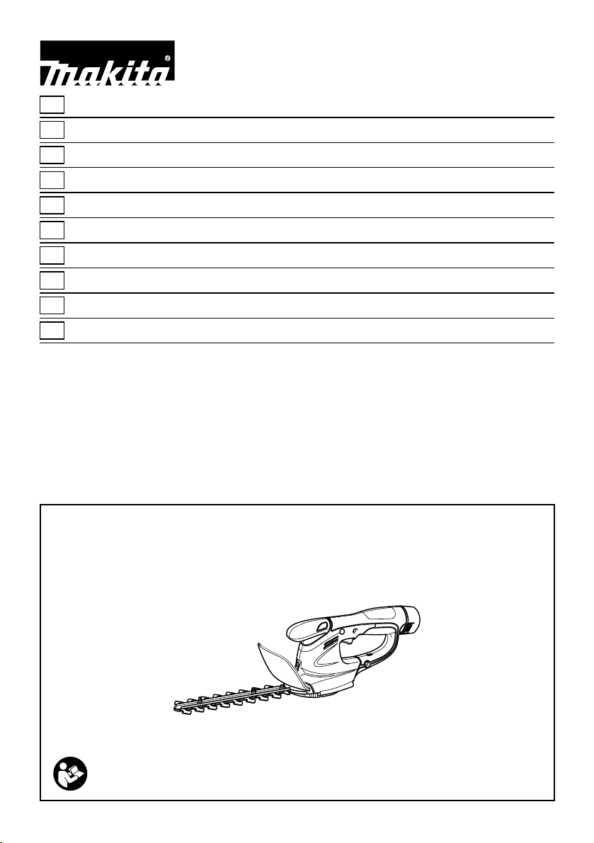
CORDLESS GRASS SHEAR
SAFETY WARNINGS
WARNING! IMPORTANT READ CAREFULLY all
safety warnings and all instructions BEFORE USE.
Failure to follow the warnings and instructions may
result in electric shock, fire and/or serious injury.
Save all warnings and
instructions for future reference.
General instructions
1. To ensure correct operation, user has to read this
instruction manual to make himself familiar with
the handling of the equipment. Users insufficiently
informed will risk danger to themselves as well as
others due to improper handling.
2. Never allow children, persons with reduced
physical, sensory or mental capabilities or lack of
experience and knowledge or people unfamiliar
with these instructions to use the machine, local
regulations may restrict the age of the operator.
3. Use the equipment with the utmost care and
attention.
4. Operate the equipment only if you are in good
physical condition. Perform all work calmly and
carefully. Use common sense and keep in mind
that the operator or user is responsible for
accidents or hazards occurring to other people or
their property.
5. Never operate the machine while people,
especially children, or pets are nearby.
6. Never use the equipment after consumption of
alcohol or drugs, or if feeling tired or ill.
7. The motor is to be switched off immediately in
case that the equipment shows any problem or
abnormal sign.
8. Switch off and remove the battery cartridge when
resting and when leaving the equipment
unattended, and place it in a safe location to
prevent danger to others or damage to the
equipment.
9. Don't force the equipment. It will do the job better
and with less likelihood of a risk of injury at the
rate for which it was designed.
10. Don't overreach. Keep proper footing and
balance at all times.
11.
Avoid using the machine in bad weather conditions
especially when there is a risk of lightning,
Personal protective equipment
1. Dress Properly. The clothing worn should be
functional and appropriate, i.e. it should be tight-
fitting but not cause hindrance. Do not wear either
jewelry or clothing which could become entangled.
Wear protective hair covering to contain long hair.
2. Wear eye protection and stout shoes at all times
while operating the machine.
3. Always wear substantial footwear and long
trousers while operating the machine,
Electrical and battery safety
1. Avoid dangerous environment. Don't use the
equipment in damp or wet locations or expose it
to rain. Water entering an equipment will increase
the risk of electric shock.
2. Recharge only with the charger specified by the
manufacturer. A charger that is suitable for one
type of battery pack may create a risk of fire when
used with another battery pack.
3. Use power tools only with specifically designated
battery packs. Use of any other battery packs
may create a risk of injury and fire.
4. When battery pack is not in use, keep it away
from other metal objects, like paper clips, coins,
keys, nails, screws or other small metal objects,
that can make a connection from one terminal to
another. Shorting the battery terminals together
may cause burns or a fire.
5. Under abusive conditions, liquid may be ejected
from the battery; avoid contact. If contact
accidentally occurs, flush with water. If liquid
contacts eyes, additionally seek medical help.
Liquid ejected from the battery may cause
irritation or burns.
6. Do not dispose of the battery(ies) in a fire. The
cell may explode. Check with local codes for
possible special disposal instructions.
7. Do not open or mutilate the battery(ies).
Released electrolyte is corrosive and may cause
damage to the eyes or skin. It may be toxic if
swallowed.
Starting up the equipment
1. Make sure that there are no children or other
people nearby, also pay attention to any animals
in the working vicinity. Otherwise stop using the
equipment.
2. Before use always check that the equipment is
safe for operation. Check the security of the
cutting tool and the guard and the switch
trigger/lever for easy and proper action. Check for
clean and dry handles and test the function of the
start/stop.
3. Check damaged parts before further use of the
equipment. A guard or other part that is damaged
should be carefully checked to determine that it
will operate properly and perform its intended

10
function. Check for alignment of moving parts,
binding of moving parts, breakage of parts,
mounting, and any other condition that may affect
its operation. A guard or other part that is
damaged should be properly repaired or replaced
by our authorized service center unless indicated
elsewhere in this manual.
4. Switch on the motor only when the hands and
feet are away from the cutting tool.
5. Before starting make sure that the cutting tool has
no contact with any objects.
Method of operation
1. Only use the equipment in good light and visibility.
During the winter season beware of slippery or
wet areas, ice and snow (risk of slipping). Always
ensure a safe footing on slopes and be sure to
walk and never run.
2. Take care against injury to feet and hands from
the cutting tool.
3. Never stand on a ladder and run the equipment.
4. Never climb up into trees to perform cutting
operation with the equipment.
5. Never work on unstable surfaces.
6. Remove sand, stones, nails etc. found within the
working range. Foreign particles may damage the
cutting tool and can cause dangerous kick-backs.
7. Should the cutting tool hit stones or other hard
objects, immediately switch off the motor and
inspect the cutting tool.
8. Inspect the cutting tool at short regular intervals
for damage (detection of hairline cracks by
means of tapping-noise test).
9. Before commencing cutting, the cutting tool must
have reached full working speed.
10. The cutting tool has to be equipped with the
appropriate guard. Never run the equipment with
damaged guards or without guards in place!
11. All protective installations and guards supplied
with the equipment must be used during
operation.
12. Always remove the battery cartridge from the
equipment:
−whenever leaving the equipment unattended;
−before clearing a blockage;
−before checking, cleaning or working on the
equipment;
−after striking a foreign object;
−whenever the equipment starts vibrating
abnormally.
13. Always ensure that the ventilation openings are
kept clear of debris.
14. Cutting means continues to run after the motor is
switched off.
Cutting Tools
1. Employ only the correct cutting tool for the job in
hand.
Maintenance instructions
1. The condition of the equipment, in particular of
the cutting tool of the protective devices must be
checked before commencing work.
2.
Turn off the motor and remove the battery cartridge
before carrying out maintenance, replacing cutting
tools or cleaning the equipment or cutting tool.
3. Check loose fasteners and damaged parts such
as cracks in the cutting attachment.
4. Follow instructions for lubricating and changing
accessories.
5. When not in use, store the equipment indoors in
dry and high or locked-up place - out of the reach
of children. Clean and maintain before storage.
6. Use only the manufacturer's recommended
replacement parts and accessories.
7. Inspect and maintain the equipment regularly,
especially before/after use. Have the equipment
repaired only by our authorized service center.
8. Keep handles dry, clean and free from oil and
grease.
KEEP FOR FUTURE
REFERENCE
WARNING:
DO NOT let comfort or familiarity with product
(gained from repeated use) replace strict adherence
to safety rules for the subject product. MISUSE or
failure to follow the safety rules stated in this
instruction manual may cause serious personal
injury.
ENC009-3
IMPORTANT SAFETY
INSTRUCTIONS
FOR BATTERY CARTRIDGE
1. Before using battery cartridge, read all
instructions and cautionary markings on (1)
battery charger, (2) battery, and (3) product
using battery.
2. Do not disassemble battery cartridge.
3. If operating time has become excessively
shorter, stop operating immediately. It may
result in a risk of overheating, possible burns
and even an explosion.
4. If electrolyte gets into your eyes, rinse them
out with clear water and seek medical
attention right away. It may result in loss of
your eyesight.
5. Do not short the battery cartridge:
(1) Do not touch the terminals with any
conductive material.
(2) Avoid storing battery cartridge in a
container with other metal objects such
as nails, coins, etc.

11
(3) Do not expose battery cartridge to water
or rain.
A battery short can cause a large current flow,
overheating, possible burns and even a
breakdown.
6. Do not store the tool and battery cartridge in
locations where the temperature may reach or
exceed 50 ゚C (122 ゚F).
7. Do not incinerate the battery cartridge even if
it is severely damaged or is completely worn
out. The battery cartridge can explode in a fire.
8. Be careful not to drop or strike battery.
9. Do not use a damaged battery.
10. Follow your local regulations relating to
disposal of battery.
SAVE THESE INSTRUCTIONS.
CAUTION: Only use genuine Makita batteries.
Use of non-genuine Makita batteries, or batteries that
have been altered, may result in the battery bursting
causing fires, personal injury and damage. It will also
void the Makita warranty for the Makita tool and charger.
Tips for maintaining maximum battery life
1. Charge the battery cartridge before
completely discharged.
Always stop tool operation and charge the
battery cartridge when you notice less tool
power.
2. Never recharge a fully charged battery
cartridge.
Overcharging shortens the battery service life.
3. Charge the battery cartridge with room
temperature at 10 ゚C - 40 ゚C (50 ゚F - 104 ゚F).
Let a hot battery cartridge cool down before
charging it.
FUNCTIONAL DESCRIPTION
CAUTION:
• Always be sure that the tool is switched off and the
battery cartridge is removed before adjusting or
checking function on the tool.
Installing or removing battery cartridge
Fig.1
CAUTION:
• Always switch off the tool before installing or
removing of the battery cartridge.
• Hold the tool and the battery cartridge firmly
when installing or removing battery cartridge.
Failure to hold the tool and the battery cartridge
firmly may cause them to slip off your hands and
result in damage to the tool and battery cartridge
and a personal injury.
To remove the battery cartridge, withdraw it from the
tool while pressing the buttons on both sides of the
cartridge.
To install the battery cartridge, hold it so that the battery
cartridge front shape fits to that of the battery
installment opening and slip it into place. Insert it all the
way until it locks in place with a little click.
CAUTION:
• Always insert the battery cartridge all the way until
it locks in place. If not, it may accidentally fall out
of the tool, causing injury to you or someone
around you.
• Do not install the battery cartridge forcibly. If the
cartridge does not slide in easily, it is not being
inserted correctly.
Battery protection system
The tool is equipped with a battery protection system.
This system automatically cuts off power to the motor to
extend battery life.
The tool will automatically stop during operation if the
tool and/or battery are placed under one of the following
conditions:
• Overloaded:
The tool is operated in a manner that causes
it to draw an abnormally high current.
In this situation, release the switch trigger on
the tool and stop the application that caused
the tool to become overloaded. Then pull the
switch trigger again to restart.
• Low battery voltage:
The remaining battery capacity is too low
and the tool will not operate. If you pull the
switch trigger, the motor runs again but stops
soon. In this situation, remove and recharge
the battery.

12
Switch action
Fig.2
CAUTION:
• Before inserting the battery cartridge into the tool,
always check to see that the switch trigger
actuates properly and returns to the "OFF"
position when released.
To prevent the switch trigger from being accidentally
pulled, a lock-off button is provided.
To start the tool, depress the lock-off button and pull the
switch trigger. Release the switch trigger to stop. The lock-
off button can be pressed from either right or left side.
Indication lamp
Fig.3
Running the tool allows the indication lamp to show the
battery cartridge capacity status.
When the tool is also overloaded and has stopped
during operation, the lamp lights up in red.
Refer to the following table for the status and action to
be taken for the indication lamp.
Note 1: The time at which the indication lamp lights up varies by the temperature
around the work area and the battery cartridge conditions.
Indication lamp
The lamp blinks in red.
The lamp lights up in red.
(Note 1)
The lamp lights up in red.
(Note 1)
Status
This indicates the appropriate
time to replace the battery
cartridge when the battery
power becomes low.
This function works when the
battery power is almost used
up. At this time, tool stops
immediately.
Autostop due to overload.
Action to be taken
Recharge the battery cartridge
as soon as possible.
Recharge the battery cartridge.
Turn off the tool.
010970
OPERATION
Refer to the Safety Warnings before operation.
CAUTION:
• Be careful not to accidentally contact a metal
fence or other hard objects while trimming. The
blade will break and may cause serious injury.
• Also, be careful for the shear blade not to contact
the ground.
• Overreaching with a hedge trimmer, particularly
from a ladder, is extremely dangerous. Do not
work from anything wobbly or infirm.
Fig.4
Do not attempt to cut branches thicker than 10 mm
diameter with this trimmer. These should first be cut with
shears down to the hedge trimming level.
CAUTION:
• Do not cut off dead trees or similar hard objects.
Failure to do so may damage the tool.
• Do not trim the grass or weeds while using hedge
shear blade. The shear blade may entangle the
grass or weeds.
Fig.5
Hold the trimmer with one hand, depress the lock-off
button and pull the switch trigger and then move it in
front of your body.
Fig.6
As a basic operation, tilt the blades towards the
trimming direction and move it calmly and slowly at the
speed rate of 3 - 4 seconds per meter.
Fig.7
To cut a hedge top evenly, it helps to tie a string at the
desired hedge height and to trim along it, using it as a
reference line.
Fig.8
Attaching the chip receiver (accessory) on the tool when
trimming the hedge straight can avoid cut off leaves'
being thrown away.
Fig.9
To cut a hedge side evenly, it helps to cut from the
bottom upwards.
Fig.10
Trim boxwood or rhododendron from the base toward
the top for a nice appearance and good job.

13
Installing or removing chip receiver
(accessory)
CAUTION:
• Always be sure that the tool is switched off and the
battery cartridge is removed before installing or
removing chip receiver.
NOTE:
• When replacing the chip receiver, always wear
gloves so that hands and face does not directly
contact the blade. Failure to do so may cause
personal injury.
• When replacing the chip receiver, always be
careful not to contact the shear blades.
• The chip receiver receives cut-off leaves and
alleviates collecting thrown-away leaves. This can
be installed on either side of the tool.
Fig.11
Place the chip receiver on the shear blades so that its
slits overlap with the screws on the shear blades and
secure it using two clamping nuts.
To remove the chip receiver, loosen and remove the two
clamping nuts and then take it out.
MAINTENANCE
CAUTION:
• Always be sure that the tool is switched off and the
battery cartridge is removed before attempting to
perform inspection or maintenance.
Cleaning the tool
Clean out the tool by wiping off dust with a dry or soap-
dipped rag.
CAUTION:
• Never use gasoline, benzine, thinner, alcohol or
the like. Discoloration, deformation or cracks may
result.
Shear blade maintenance
Fig.12
Smear the blade before and once per hour during
operation using machine oil or similars.
Fig.13
After operation, remove dust from both sides of the
blade with wired brush, wipe it off with a rag and then
apply enough low-viscosity oil, such as machine oil etc.
and spray-type lubricating oil.
CAUTION:
• Do not wash the blades in water. Failure to do so
may cause rust or damage on the tool.
Removing or installing hedge shear blades
CAUTION:
• Before removing or installing shear blades, always
be sure that the tool is switched off and the battery
cartridge is removed.
• When replacing the shear blades, always wear
gloves without removing blade cover so that hands
and face do not directly contact the blade. Failure
to do so may cause personal injury.
NOTE:
• Do not wipe off grease from the gear and crank.
Failure to do so may cause damage to the tool.
• For specific way of removing and installing shear
blades refer to the reverse of a package for
accessory shear blades.
Removing the hedge shear blades
Fig.14
CAUTION:
• Install the blade cover before removing or
installing the shear blades.
Reverse the tool.
Fig.15
To remove the shear blades, press the locking lever and
with the locking lever pressed turn the undercover
counterclockwise until the symbol on the undercover
is aligned with the symbol on the locking lever.
Fig.16
Take out the undercover from the tool.
Fig.17
Loosen two screws with a coin and similars and remove
the shear blades.
NOTE:
• Do not remove the screws. Without removing the
screws loosened, shear blades can be removed.
Fig.18
Remove the crank from the shear blades.
NOTE:
• The crank may remain in the tool.

14
Installing the hedge shear blades
12
3
010904
Prepare the crank, the undercover and new shear
blades.
12
010905
Adjust the three detent pin position so that these three pins
are aligned with the basic alignment line on the tool housing.
1
2
3
4
015809
Fit the crank with its recessed part facing downward
onto the detent pins. At this time, apply a small amount
of grease to the periphery of the crank using grease that
the shear blades as optional accessory are provided
with or that remains inside gear housing.
1
2
3
010907
Overlap the oval hole in the upper blade with that in the
lower one. Move the shear blades so that the hole in the
base plate of shear blades are positioned in the center
of these overlapped oval holes.
Fig.19
Take out the blade cover from the old shear blades and
fit it onto the new ones for easy handling during the
replacement of blades.
Fig.20
Turn the shear blades upside down and install it so that
pin on the tool fit in the hole in the shear blades. Fit the
bent part of the base plate of the shear blades to the
groove in the tool housing. Then make sure that the
base plate of the shear blades is set in place.
Fig.21
Tighten two screws with a coin or similars firmly.
Fig.22
Place the undercover so that the symbol on the
undercover is aligned with the symbol on the
locking lever.
Fig.23
Press the undercover down and with the undercover
pressed down turn the undercover clockwise until the
symbol on the label is aligned with the symbol on
the locking lever (the undercover is completely locked.).
Fig.24
At this time, make sure that the locking lever fits in the
groove in the undercover.
CAUTION:
• Never use the tool without installing the
undercover on it.
Remove the blade cover and then turn on the tool to
check it for proper movement.
NOTE:
• When the shear blades does not operate properly,
there is a poor fit between the blades and crank.
Redo from the beginning.
Storage
Fig.25
The hook hole in the tool bottom is convenient for
hanging the tool from a nail or screw on the wall.
1. Recessed part of crank
2. Crank
3. Apply grease
4. Pins
1. Crank
2. Undercover
3. Shear blades
1. Basic alignment line on the tool housing
2. Pins
1. Oval holes that are overlapped
2. Hole in the base plate of shear blades
3. Base plate

15
Put the blade cover on the shear blades so that the
blades are not exposed. Store the tool out of the reach
of children carefully.
Store the tool in the place not exposed to water and rain.
To maintain product SAFETY and RELIABILITY, repairs,
carbon brush inspection and replacement, any other
maintenance or adjustment should be performed by
Makita Authorized Service Centers, always using Makita
replacement parts.
OPTIONAL ACCESSORIES
CAUTION:
• These accessories or attachments are
recommended for use with your Makita tool
specified in this manual. The use of any other
accessories or attachments might present a risk of
injury to persons. Only use accessory or
attachment for its stated purpose.
If you need any assistance for more details regarding
these accessories, ask your local Makita Service Center.
• Hedge shear blade cover
• Hedge shear blade assembly
• Chip receiver for hedge trimming
• Makita genuine battery and charger
For cordless grass shear use
This tool can be used as a grass shear by using the
grass shear blade (optional accessory) and 2-way
change set.
To use this tool as a grass shear, replacing the hedge
shear blades with the grass shear blades is required.
For removing the hedge trimmer blades, refer to the
aforementioned section titled "Removing the hedge
shear blades".
For installing the grass shear blade, refer to the section
below titled "Installing or removing grass shear blades".
• Grass shear blade assembly (for Grass Shear)
• 2-way change set consisting of the following three
accessories
• Grass shear blade cover (for Grass Shear)
• Storage case (for blade bottom section)
• Base frame (for Grass Shear)
1
234
011042
• Long handle attachment (for Grass Shear)
NOTE:
• Some items in the list may be included in the tool
package as standard accessories. They may differ
from country to country.
ASSEMBLY
CAUTION:
• Always be sure that the tool is switched off and the
battery cartridge is removed before carrying out
any work on the tool.
Installing or removing blade cover
CAUTION:
• Be careful not to contact the shear blade when
installing or removing the blade cover. Contacting
the shear blade may cause personal injuries.
Fig.26
Fig.27
Slide the blade cover from the tool's side until the shear
blade completely hides itself and then push in it lightly
towards the tool from the front.
To remove the blade cover, take the above installation
procedure in reverse.
1. Grass shear blade
2. Grass shear blade cover
3. Storage case
4. Base frame

16
Installing or removing grass shear blades
CAUTION:
• Always be sure that the tool is switched off and the
battery cartridge is removed before installing or
removing shear blades. Failure to switch off and
remove the battery cartridge from the tool may
result in serious injury from accidental start-up.
• When replacing the shear blade, always wear
gloves without removing blade cover so that hands
and face does not directly contact the blade.
Failure to do so may cause personal injury.
NOTE:
• Do not wipe off grease from the gear and crank.
Failure to do so may cause damage to the tool.
• For specific way of removing and installing shear
blades refer to the reverse of a package for
accessory shear blades.
12 3
010895
To install the grass shear blade, prepare the crank,
undercover and new grass shear blade.
Fig.28
Take out the blade cover from the old shear blades and
fit it onto the new ones for easy handling during the
replacement of blades.
12
010897
Adjust the three detent pin position so that these pins
are lined up at right angle in relation to the basic
alignment line on the tool housing.
Fig.29
Fit the crank with its recessed part facing upwards onto
the detent pins. At this time, apply a small amount of
grease to the periphery of the crank using grease that
the shear blades as optional accessory are provided
with or that remains inside gear housing.
Fig.30
Overlap the oval hole in the upper blade with that in the
lower one. Move the shear blades so that the hole in the
base plate of shear blades are positioned in the center
of these overlapped oval holes.
Fig.31
Turn the shear blades upside down and install it so that
the detent pins on the tool fit in the hole in the shear
blades. Make sure that the shear blades are set in place
securely as far as they reach the base plate.
Fig.32
Place the undercover so that the symbol on the
undercover is aligned with the symbol on the
locking lever.
Fig.33
Press the undercover down and with the undercover
pressed down turn the undercover clockwise until the
symbol on the label is aligned with the symbol
on the locking lever (the undercover is completely
locked.).
Fig.34
At this time, make sure that the locking lever fits in the
groove in the undercover.
Remove the blade cover and then turn on the tool to
check it for proper movement.
NOTE:
• When the shear blades does not operate properly,
there is a poor fit between the blades and crank.
Redo from the beginning.
Fig.35
Remove the base frame and place the tool upside down.
CAUTION:
• Before placing the tool upside down, be sure to
remove the base frame (only for the tool changed
to the grass shear mode).
Fig.36
To remove the shear blade, press the locking lever and
with the locking lever pressed turn the undercover
counterclockwise until the symbol on the undercover
is aligned with the symbol on the locking lever.
Fig.37
Take out the undercover, shear blade and crank in order
from the tool.
1. Crank
2. Undercover
3. Shear blades
1. Basic alignment line on the tool housing
2. Pins

17
1
011043
NOTE:
• In the 2-way usage, the removed hedge shear
blade need to be sheared in the blade storage
case and then stored for future use.
Installing or removing base frame
CAUTION:
• Before installing or removing base frame, be sure
to install the blade cover.
• When installing or removing base frame, take care
that your fingers are not be pinched between the
tool and base frame.
Fig.38
To remove the base frame, upset the tool and take it out
of the groove grabbing its bottom.
Fig.39
To install the base frame, fit the protrusion of base
frame near the change lever into the hole for the
sheared grass height setting. With the base frame so
fitted, pull the lower part of base frame and fit the other
part of the base frame in the groove in the tool.
Adjusting the shearing height
Fig.40
Changing the position of holding the change lever
allows three-stepped setting for sheared grass height
(10 mm, 15 mm, 25 mm).
To change setting, tilt the change lever for the base
frame position and with the change lever tilted move it
up or down along the tool surface until the protrusion on
base frame fits in one of the holes in the tool and
release it.
OPERATION
WARNING:
• Keep hands away from blades.
CAUTION:
• Smear the blade before and once per hour during
operation using machine oil or similars.
• Avoid operating the tool under the scorching
sunlight as much as practicable. When operating
the tool, be careful of your physical conditions.
• Hold the tool with one hand. Do not hold the front
bulge of the tool as a grip.
Fig.41
Turn the tool on after adjusting the shearing height and
hold it so that the foot of the tool rest on the ground.
Then gently move the tool forward into the area to be
cut.
Fig.42
When trimming around curb, fence or trees, move the
tool along them. Be careful for the blade not to contact
them.
Fig.43
When trimming sprouts or foliage of a small tree,
remove the base frame from the tool and cut little by
little.
Shear big branches to your desired height beforehand
using branch scissors before using this tool.
CAUTION:
• When trimming twigs and foliage, do not attempt
to trim too much at a time. Proceed gently. Also do
not attempt to cut thick branches.
• Do not let the shear blades contact the grounds
during operation. The blades will be dulled,
causing poor performance.
• Do not trim wet grass or foliage of small trees.
1. Storage case

18
SLOVENŠČINA (izvirna navodila)
Razlaga splošnega pogleda
1-1. Baterijski vložek
1-2. Gumbi
2-1. Sprostilni gumb
2-2. Sprožilno stikalo
3-1. Kontrolna lučka
6-1. Smer rezanja s škarjami
6-2. Nagnite rezila
6-3. Površina žive meje, ki jo boste
rezali
7-1. Vrvica
11-1. Vpenjalni matici
11-2. Prestreznik odrezanega materiala
11-3. Vijaki na rezilih škarij
11-4. Pokrov rezila, ki ga je treba vedno
namestiti preden namestite
prestreznik odrezanega materiala
12-1. Ščetka
13-1. Strojno olje
14-1. Pokrov rezila
15-1. Spodnji pokrov
15-2. Zaklepna ročica
15-3. Pritisnite
15-4. Obrnite
16-1. Spodnji pokrov
17-1. Vijaki
18-1. Ročična
18-2. Rezila škarij
19-1. Pokrov rezila
20-1. Zaviti del osnovne plošče rezila
škarij
21-1. Vijaki
22-1. Zaklepna ročica
22-2. Spodnji pokrov
24-1. Utor v spodnjem pokrovu
24-2. Zaklepna ročica
25-1. Luknja za obešanje
26-1. Rezila škarij
26-2. Okvir podstavka
26-3. Pokrov rezila
28-1. Pokrov rezila
28-2. Rezila škarij
29-1. Ugreznjen del ročice
29-2. Zatiči
29-3. Ročična
29-4. Nanesite mast
30-1. Osnovna plošča
30-2. Luknja v osnovni plošči rezila
škarij
30-3. Ovalne, prekrivajoče se luknje
32-1. Spodnji pokrov
32-2. Zaklepna ročica
34-1. Utor v spodnjem pokrovu
34-2. Zaklepna ročica
35-1. Pokrov rezila
36-1. Spodnji pokrov
36-2. Zaklepna ročica
36-3. Pritisnite
36-4. Obrnite
37-1. Spodnji pokrov
37-2. Rezilo škarij
37-3. Ročična
38-1. Utor
38-2. Okvir podstavka
39-1. Preklopnik
39-2. Izboklina na okvirju podstavka
39-3. Okvir podstavka
40-1. Preklopnik
40-2. Izboklina na okvirju podstavka
40-3. Okvir podstavka
TEHNIČNI PODATKI
Model UH200D
Dolžina rezila 200 mm
Rezi na minuto (min-1) 1.250
Skupna dolžina 460 mm
Neto teža 1,2 kg
Nazivna napetost D.C. 10,8 V
Baterijski vložek BL1013
Polnilnik akumulatorjev DC10WA
• Zaradi našega nenehnega programa raziskav in razvoja si pridržujemo pravico do spremembe tehničnih podatkov brez obvestila.
• Tehnični podatki in baterijski vložki se lahko razlikujejo od države do države.
• Teža z baterijskim vložkom je v skladu z EPTA-postopkom 01/2003
END010-4
Simboli
Naslednji simboli se uporabljajo v povezavi s strojem.
Pred uporabo proizvoda se obvezno seznanite z
njihovim pomenom.
・Potrebna je posebna pozornost in
previdnost.
・Preberite navodila za uporabo.
・Nevarnost; pazite se letečih predmetov.
・Prisotne osebe se ne smejo približevati.
・Ko motor ugasnete, se rezila še vedno
premikajo.
・Ne izpostavljajte vlagi.
・Le za države EU
Električnega orodja ali akumulatorja ne
odlagajte skupaj z gospodinjskimi odpadki!
V skladu z Evropsko direktivo o odpadni
električni in elektronski opremi in o
baterijah in akumulatorjih ter odpadnih
baterijah in akumulatorjih in z njunim
izvajanjem v skladu z državno
zakonodajo se morajo električna oprema,
baterije in akumulatorji, ki so prišli do
konca svojega življenjskega cikla, zbirati
ločeno in se vrniti v okoljsko združljivo
ustanovo za recikliranje.
Cd
Ni-MH
Li-ion

19
ENE014-1
Namenska uporaba
Orodje je namenjeno za rezanje žive meje.
ENG905-1
Hrup
Tipični, z A ocenjeni vrednosti hrupa glede na EN60745:
Raven zvočnega tlaka (LpA): 73,7 dB (A)
Odstopanje (K): 2,5 dB (A)
Nivo hrupa med delom lahko preseže 80 dB (A).
Uporabljajte zaščito za sluh
ENG900-1
Vibracije
Skupne vrednosti vibracij (vektorska vsota treh osi) po
EN60745:
Oddajanje tresljajev (ah): 2,5 m/s2ali manj
Odstopanje (K): 1,5 m/s2
ENG901-1
• Navedena vrednost oddajanja vibracij je bila
izmerjena v skladu s standardnimi metodami
testiranja in se lahko uporablja za primerjavo
orodij.
• Navedena vrednost oddajanja vibracij se lahko
uporablja tudi pri predhodni oceni izpostavljenosti.
OPOZORILO:
• Oddajanje vibracij med dejansko uporabo
električnega orodja se lahko razlikuje od navedene
vrednosti oddajanja, odvisno od načina uporabe
orodja.
• Upravljavec mora za lastno zaščito poznati
varnostne ukrepe, ki temeljijo na oceni
izpostavljenosti v dejanskih pogojih uporabe
(upoštevajočceloten delovni proces v trenutkih, ko
je orodje izključeno in ko deluje v prostem teku z
dodatkom časa sprožitve).
Striženje trave z izbirnimi rezili škarij za travo
ENG905-1
Hrup
Tipični, z A ocenjeni vrednosti hrupa glede na
IEC60335:
Raven zvočnega tlaka (LpA): 75,9 dB (A)
Odstopanje (K): 2,5 dB (A)
Nivo hrupa med delom lahko preseže 80 dB (A).
Uporabljajte zaščito za sluh
ENG900-1
Vibracije
Skupne vrednosti vibracij (vektorska vsota treh osi) po
IEC60335:
Oddajanje tresljajev (ah): 2,5 m/s2ali manj
Odstopanje (K): 1,5 m/s2
ENG901-1
• Navedena vrednost oddajanja vibracij je bila
izmerjena v skladu s standardnimi metodami
testiranja in se lahko uporablja za primerjavo
orodij.
• Navedena vrednost oddajanja vibracij se lahko
uporablja tudi pri predhodni oceni izpostavljenosti.
OPOZORILO:
• Oddajanje vibracij med dejansko uporabo
električnega orodja se lahko razlikuje od navedene
vrednosti oddajanja, odvisno od načina uporabe
orodja.
• Upravljavec mora za lastno zaščito poznati
varnostne ukrepe, ki temeljijo na oceni
izpostavljenosti v dejanskih pogojih uporabe
(upoštevajočceloten delovni proces v trenutkih, ko
je orodje izključeno in ko deluje v prostem teku z
dodatkom časa sprožitve).
ENH021-8
Samo za evropske države
ES Izjava o skladnosti
Družba Makita izjavlja, da je/so naslednji stroj/-i:
Oznaka stroja:
Brezžične škarje za živo mejo
Št. modela / tip: UH200D
Tehnični podatki: glejte tabelo "TEHNIČNI
PODATKI".
Je skladen z naslednjimi evropskimi direktivami:
2000/14/ES, 2006/42/ES
Izdelan v skladu z naslednjim standardom ali
standardiziranimi dokumenti:
EN60745
Tehnična dokumentacija v skladu z direktivo
2006/42/ES je na voljo na:
Makita, Jan-Baptist Vinkstraat 2, 3070, Belgija
Postopek za ugotavljanje skladnosti, ki ga predpisuje
direktiva 2000/14/ES, je v skladu s prilogo V.
Izmerjena stopnja jakosti zvoka: 81,8 dB (A)
Zajamčena stopnja jakosti zvoka: 84 dB (A)
30.9.2015
000331
Yasushi Fukaya
Direktor
Makita, Jan-Baptist Vinkstraat 2, 3070, Belgija

20
ENH003-15
Samo za evropske države
ES Izjava o skladnosti
Družba Makita izjavlja, da je/so naslednji stroj/-i:
Oznaka stroja:
Brezžične škarje za travo
Št. modela / tip: UH200D
Je skladen z naslednjimi evropskimi direktivami:
2006/42/ES
Izdelan v skladu z naslednjim standardom ali
standardiziranimi dokumenti:
EN60335, EN60745
Tehnična dokumentacija v skladu z direktivo
2006/42/ES je na voljo na:
Makita, Jan-Baptist Vinkstraat 2, 3070, Belgija
30.9.2015
000331
Yasushi Fukaya
Direktor
Makita, Jan-Baptist Vinkstraat 2, 3070, Belgija
GEA010-1
Splošna varnostna opozorila za
električno orodje
OPOZORILO Preberite vsa varnostna opozorila
in navodila. Neupoštevanje opozoril in navodil lahko
vodi do električnega udara, požara, in/ali hudih telesnih
poškodb.
Shranite vsa opozorila in navodila za
kasnejšo uporabo.
GEB062-5
VARNOSTNA OPOZORILA ZA
BREZŽIČNE ŠKARJE ZA ŽIVO
MEJO
1. Ne približujte delov telesa rezilu. Ne
odstranjujte odrezanega materiala in ne držite
materiala, ki ga boste rezali, kadar se rezila
premikajo. Kadar čistite zataknjen material, se
prepričajte, ali je stikalo izklopljeno. Trenutek
nepazljivosti pri delu s škarjami za živo mejo
lahko privede do hudih telesnih poškodb.
2. Škarje za živo mejo nosite tako, da jih držite
za ročaj, rezila pa morajo biti ustavljena.
Kadar transportirate ali shranjujete škarje za
živo mejo, vedno namestite pokrov rezalne
naprave. Ustrezno rokovanje s škarjami za živo
mejo bo zmanjšalo morebitne telesne poškodbe
zaradi rezil.
3. Držite električno orodje na izoliranih držalnih
površinah, saj lahko rezilo prereže skrito
električno napeljavo. Če prerežete vodnike pod
napetostjo, dobijo napetost vsi neizolirani kovinski
deli električnega orodja, zaradi česar lahko
uporabnik utrpi električni udar.
4. Škarij za živo mejo ne uporabljajte v dežju ali v
zelo vlažnih pogojih. Električni motor ni
vodotesen.
5. Uporabnikom, ki prvičuporabljajo škarje za živo
mejo, naj pokaže izkušen uporabnik, kako jih naj
uporabljajo.
6. Škarij za živo mejo ne smejo uporabljati otroci ali
mlajši od 18 let. Mladoletniki, starejši od 16 let, so
lahko izvzeti iz te omejitve, če se usposabljajo
pod nadzorom strokovnjaka.
7. S škarjami za živo mejo delajte samo, če ste v
dobri fizični kondiciji. Če ste utrujeni, bo vaša
zbranost zmanjšana. Še posebej bodite pozorni
ob koncu delovnega dne. Vsa dela opravljajte
mirno in zbrano. Uporabnik je odgovoren za vse
poškodbe, povzročene tretjim osebam.
8. Nikoli ne uporabljajte škarij pod vplivom alkohola,
drog ali zdravil.
9. Delovne rokavice iz robustnega usnja so del
osnovne opreme škarij za živo mejo in jih je pri
delu treba vedno nositi. Prav tako nosite močne
čevlje z nedrsečim podplatom.
10. Pred začetkom dela, se prepričajte, ali so škarje v
dobrem in varnem stanju za delo. Zagotovite, da
so ščitniki pravilno nameščeni. Škarij za živo
mejo ni dovoljeno uporabljati, če niso v celoti
sestavljene.
11. Pred začetkom uporabe zagotovite trdno stojišče.
12. Med uporabo trdno držite orodje.
13. Ne uporabljajte orodja brez obremenitve po
nepotrebnem.
14. Če škarje pridejo v stik z ograjo ali drugim trdim
predmetom, takoj ugasnite motor in odstranite
akumulatorsko baterijo. Preverite škarje, ali so
poškodovane, in jih v tem primeru takoj popravite.
15. Preden škarje pregledate, odpravite napake ali
odstranite material, ki se ujel v škarje, vedno
izklopite škarje in odstranite akumulatorsko
baterijo.
16. Pred katerimi koli vzdrževalnimi deli izklopite
škarje in odstranite akumulatorsko baterijo.
17. Kadar premikate škarje za živo mejo na drugo
lokacijo, tudi med delom, vedno odstranite
akumulatorsko baterijo in namestite pokrov rezila.
Nikoli ne prenašajte ali prevažajte škarij, kadar
delujejo. Nikoli ne prijemajte škarij z rokami.
18. Po uporabi in preden shranite škarje za živo mejo
za dlje časa jih očistite (še posebej rezilo). Rahlo
naoljite rezilo in namestite pokrov. Pokrov, ki je
priložen enoti, lahko obesite na steno, kar
omogoča varen in praktičen način shranjevanja
škarij za živo mejo.
Other manuals for UH200D
7
Table of contents
Languages:
Other Makita Trimmer manuals

Makita
Makita RBC2500 User guide

Makita
Makita DUH523RT User manual

Makita
Makita DUH483 User manual

Makita
Makita EN4950H User guide

Makita
Makita BUR141 User manual

Makita
Makita DUR365U User manual

Makita
Makita DUR184L User manual

Makita
Makita EH5000W Manual

Makita
Makita UR201C User manual

Makita
Makita DBC260U User guide

Makita
Makita DUH481 User manual

Makita
Makita UM600D User manual

Makita
Makita DUH523 User manual

Makita
Makita DUR182U User manual

Makita
Makita UR016G User manual

Makita
Makita DUR184LRT User manual

Makita
Makita LXHU02Z User manual

Makita
Makita DUR193SF User manual

Makita
Makita DUR184L User manual

Makita
Makita DUR365U User manual