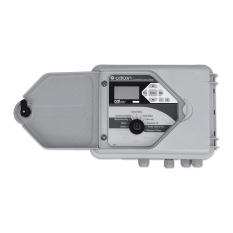
Galcon Galileo User manual


2
(The numbers in brackets are the access number in the controller)
1) Preface .................................................................................................................................................................... 4
1.1) Using the manual .............................................................................................................................. 4
1.2) The System Structure (software view) .............................................................................. 4
1.3) Operating via the computer ...................................................................................................... 6
1.4) Operating via the Controller: .................................................................................................... 6
2) Basic operation ............................................................................................................................................ 7
2.1) Operating via the computer ...................................................................................................... 7
2.2) Operating via the Controller ...................................................................................................... 9
3) Advanced Operation .......................................................................................................................... 10
3.1) Irrigation Valves ............................................................................................................................. 10
3.2) Irrigation Program ......................................................................................................................... 11
3.2.1) Programming the irrigation program: (32) .............................................. 11
3.2.1.2) Valves in the program: (321 #2-6) ........................................... 12
3.2.1.3) Irrigation quantities: (321) .............................................................. 12
3.2.1.4) Fertilizing: (321) .................................................................................... 13
3.2.1.5) Permanent (cyclic) Start Program (322) ............................. 17
3.2.1.6) Next Open Time: (322 #3-5) ........................................................ 18
3.2.2) Current Status of Irrigation Program (12) .............................................. 19
3.2.4) Irrigation Program Set Up (34) ........................................................................ 21
3.2.4.1) Water Flow Rate Protection: (3431) ....................................... 22
3.2.4.2) Pipeline Flow Rate Limit: (343 #6) .......................................... 22
3.2.4.4) Priorities: (342) ..................................................................................... 23
3.2.5) Irrigation Program Data (12) ............................................................................. 24
3.3) Filtering (53) ..................................................................................................................................... 26
3.4) Alarms: (8) .......................................................................................................................................... 30
3.5) Diaries: (2) .......................................................................................................................................... 33
3.6) Logic Conditions: (5612) .......................................................................................................... 35
3.7) Flow rate Limits ............................................................................................................................... 39
3.8) Pause Device (563) ..................................................................................................................... 39
3.9) Virtual Water Meter: (72322*) .............................................................................................. 40
3.10) Burst Protection: (in the controller: 515) .................................................................... 40
3.11) Water Pumps ................................................................................................................................. 40
3.11.1) Single Pump: ............................................................................................................. 40
3.11.2) Pump House: (51422) ........................................................................................ 40
Index

3
3.12) Evaporation (3442) .................................................................................................................. 43
3.13) Auxiliary (General) Outputs: (in the controller: 55) ............................................ 44
3.14) Valve Groups: (51132) ........................................................................................................... 46
4) Set Up (5) ........................................................................................................................................................ 47
4.1) System set up – My Field software: ................................................................................ 47
4.2) Element Definitions: ..................................................................................................................... 55
4.2.1) Irrigation valve (511) .............................................................................................. 57
4.2.2) Pipelines: (512) ......................................................................................................... 63
4.2.3) Water Meter: (513) .................................................................................................. 66
4.2.4) Fertilizer Pump: (521) ......................................................................................... 66
4.2.5) Fertilize Centers: (522) ......................................................................................... 72
4.2.6) Water Pumps: (7351) ............................................................................................ 74
4.2.7) The Plot: (542) ............................................................................................................ 75
4.2.8) RTU Setup: (724) ..................................................................................................... 76
4.2..9) Defining Outputs for System Elements: (7231) ................................ 76
4.2.10) Defining Condition Inputs: (72324) ........................................................... 77
4.2.11) Sensor Definition: (7233) ................................................................................. 77
4.2.12) General Counters: (72325) ............................................................................ 82
4.2.13) Operation Time Counters: (572) ................................................................ 82
4.2.14) Water Mixing Junction: (516) ....................................................................... 82
4.3) Controller Setup (6) ....................................................................................................... 88
5) Flow chart for operator ................................................................................................................ 91
6) The Menus .................................................................................................................................................... 92
Index

4
1.1 Using the manual
This operating manual is designed to provide basic operating instructions as well as
providing definitions for Open Field programming via the software. This manual does not
explain the hardware installation of the Galileo controller. For instructions on hardware
installation please refer to “Galileo Set Up”. This manual also does not deal with the
basic definitions of the Galileo system or the installation of the P.C software. For these
instructions please refer to “Galileo PC Center”.
1.2 The System Structure (software view)
The “Open Field Program” was designed to correlate as far as possible between the
structure of the software and the physical structure of the hydraulic system. The system is
made up of the following objects:
1.2.1 The pipeline
in the software, transfers the operating command from the irrigation valve to the
irrigation head and displays the hydraulic activity in a visual form. The system can
contain between one single pipeline and up to seventy pipelines. The pipeline’s
properties also include the main valve (e.g. the main valve is defined via the
pipelines). The pipeline properties contain additional parameters including which
pipeline (upstream) it is connected to. Using this programming method it is possible
to build a pipeline network with water flow directions. Via the pipelines, the system
prevents the operator from making setup mistakes such as defining a water meter
for one subsystem whilst it is already defined to serve another subsystem. This
setup mistake will result in the definition error “water meter not on route”. The
system can limit the water flow rate to a certain point (pipeline) in the system and
allows adopting separate fertilizing policies simultaneously in different parts of the
system (for example one plot works without fertilization whilst another area works
with fertilization). The pipeline has parameters allowing turning on the system
progressively and thus prevent opening and closing shocks and avoiding pressure
detentions. The pipeline is also for displaying purposes. It can be displayed on the
computer screen along with the water/fertilizer flow rates. It is recommended to use
as few pipelines as possible. During operation, the system controls the irrigation
valves. When the irrigation valve opens (by the program), the valve in turn opens
the pipeline that it is connected to, that pipeline next opens the pipeline that it is
connected to and so forth in ascending order (upstream). Every pipeline that opens
turns on the main valve defined in its properties as well as all other objects connected
to it (for example pumps or filter groups).
1.2.2 The irrigation valves:
The virtual object here is a direct representation of the physical object. It can be
incorporated in an irrigation program.The valve properties consists of 3 parts:
1. Set up. 2. Information 3. Accumulations. Set up includes definition of the output
(connected to the valve’s solenoid), definition of the pipeline that it is connected
to, the plot the valve belongs to and the water meter measuring the water. If you
1. Preface

5
want to set the controller according to volume (as opposed to time) it is essential to
define the water meters. Information includes: valve status, the program in which it is
programmed, flow rate and date of last irrigation. It also shows periodic and last day
accumulations.
1.2.3 The plot:
The plot is an agricultural term that receives virtual meaning in this system. The plot
is created in order to allow the division of large systems into smaller subsystems
that are easier to control. The plot allows definition of valves and even apportioning
pipelines to ease and simplify the controlling of the system. It is possible to work
without any plots, several plots (including one plot that is part of another plot). The
plots provide “zooming” on the P.C system.
1.2.4 The Water Meter:
The water meter, like the valve, is a direct representation of the physical object. Its
properties also consist of 3 parts: 1. Set up. 2. Information 3. Accumulations. As
previously explained, the water meter is incorporated in the valve properties. The
water meter counts the water of the valves defined to use it. One water meter can serve
several valves at the same time. In this case it divides the water between the valves
according to the relative flow rates. (For more details see “definitions and settings”).
1.2.5 Fertilizer pump: The fertilizer pump, like the valve, is a direct representation of
the physical object. Its properties also consist of 3 parts: 1. Set up. 2. Information
3. Accumulations. The fertilizer pump has many parameters (see “definitions and
settings”). The fertilizer pump is incorporated in the irrigation program or in the
fertilizer center and operated accordingly.
1.2.6 Fertilizer center:
The fertilizer center allows working simultaneously with a number of fertilizer pumps
along with one valve or with a group of valves whilst maintaining constant fertilizing
ratios between the fertilizers and in accordance with the water capacity. In addition,
the fertilizer center allows control over the EC and pH of the irrigation water. Each
fertilizer center consists of 10 fertilizer programs that can afterwards be used in the
irrigation program.
1.2.7 Irrigation program:
The irrigation program object is the heart of the system and is the object by which
the operator controls the irrigation system. The irrigation program’s properties are
divided into three main parts:
1.2.7.1 Which: Which valves are operating in the program.
1.2.7.2 Quantity:
Amounts of: working time, water and fertilizer volume, water and
fertilizer work methods.
1. Preface

6
1.2.7.3 When:
The time the irrigation starts, date, number of cycles etc.
• In addition, the irrigation program contains informative data and definitions
(see following sections).
•
See more information about the irrigation program in the operating section.
1.3 Operating via the computer:
The computer program is a graphic program and once defined, it is simple to operate
(in spite of the system sometimes being very complex) and provides good orientation
even to operators that are not totally familiar with hydraulic systems. Whilst operating the
computer the user is provided with a map or diagram of the field showing each object in
accordance with its geographical position. The operator can easily see both which events
are taking place and where they are taking place. By clicking on the object the operator
can see the object’s properties (set up, information, accumulations etc.) In addition, when
one object is incorporated in another object, clicking on the incorporated object number
leads to its properties being displayed and they can even be altered. For example: Clicking
on the valve number of a valve that is incorporated in the irrigation program displays the
valve’s properties. It is important to know that the memory and operating data (including
definitions) are only stored in the controller (not on the P.C). When a new screen opens,
the computer program requests the relevant data from the controller in order to create the
screen. A key appears on all screens that allow programming (data changes).
Click on the key in order to edit data.
This action changes the screen into editing mode whereby it is possible to move
between the cells and alter the required data. At the end of editing click on the
key again. This action causes the screen data to be sent to the controller.
1.4 Operating Via the Controller:
The data in the controller is organized in tables. Each table consists of rows and columns.
The rows represent the various objects and the columns represent the different fields of
the object’s properties. For example in the irrigation program operating table, the rows are
irrigation programs i.e. row number 1 belongs to program number 1, row number 2 belongs
to program number 2 and so forth. The same table’s columns contain the respective
program’s properties. For example: amount of water, start time, operating days etc. The
controller is organized in menu form allowing access to the tables. Each menu is in fact a
list of objects that can in turn be divided into sub menus or contain tables. Moving between
the menus is by the use of the up and down arrows and moving inside the tables is by
the use of the up, down, right and left arrows. To go down a level click <enter>, in order
to go up a level click <exit>. On narrow screened controllers each screen is a single cell
in the table or one part of the menu. On the wide screened controllers several figures are
displayed: an entire menu or several fields of an object (described as a table row in the
data organization section). Tables can also be accessed by entering the table number
(shortcut). The table number is shown in the flow chart and in the menu details appearing
at the end of this manual.
1. Preface

7
2. Basic operation
2.1 Operating via the computer:
The simplest operation is by using the operation table. Click on the “operate” button on
the main screen.
2.1.1 The following Operation Table screen opens:
This table is actually an irrigation program table (each row is an irrigation program
and each column is a field in the irrigation program’s properties).
2.1.1.1 Program Active and Status:
In order to activate a program, set it to active in the first column from the left.
The second left hand column shows (information only) if the program is active
or not. An empty cell means that the program is inactive.
2.1.1.2 The next column shows the program status. It shows activity, alarms and
programming errors.
2.1.1.3 As previously explained the irrigation program is divided into 3 parts:
2.1.1.3.1 Which
The “which” in this table is the valves’ numbers operated by the program.
The cell under each valve in the program contains the individual valve
number. As can be seen, up to 5 valves can be used in each program.
(In fact it is possible to program more valves by using valve groups – see
advanced operations).

8
2.1.1.3.2 Quantity –
Water unit must be checked first and then the quantity is entered.
2.1.1.3.2.1 Select the water unit under the water heading (pressing the cell
shows the different options) the options are:
2.1.1.3.2.1.1 MM.SS - Irrigating by time (minutes minutes.seconds
seconds) i.e. in the water amount the digits before the
decimal point are the number of minutes and the digits after
the decimal point are the number of seconds.
2.1.1.3.2.1.2 M3 (THG) -
irrigating by volume in cubic meters – enter the
desired water quantity.
2.1.1.3.2.1.3 M3/Hectare (THG/acre) -
enter the desired amount of water
per hectare.
The controller multiplies this number by the area
as defined in the valve definition. The result is placed in the
“remain” column and the irrigation is carried out according to
this amount.
2.1.1.3.2.1.4 Evaporation -This option allows automatic operation
according to evaporation rates if using an evaporation meter
or upon entering evaporation rates manually. (See detailed
explanation in advanced operation).
After selecting the water unit enter the required quantity
(according to the selected unit). It is also possible to add
fertigation by clicking the Fert Multi Prog button (see more in
advanced operation).
2.1.1.3.2.2 Timing
The three columns under the heading next open: hour, days, cycles
show when the next irrigation program starts. The “hour” column
shows the hour that the next program starts. The “days” column
shows how many days until the next program starts (0 means that
the next program starts today). The “cycle” column shows how many
times (cycles) the program will run. If all of the parameters are 0
the program will not run at all. These data can be manually altered.
These data are also automatically updated by the permanent program
(see advanced operation). The program can also be run manually
(immediately) by checking the option in the manual operation column.
(For further details please see advanced operation).
Minimal Programming to Start Irrigation
1. Activate the program
2. Enter valves into the program
3. Enter the water unit and water quantity.
4. Enter the activating factor (next opening or manual operation).
2. Basic operation

9
2.1.2 Current status display:
Back in the main screen the currently operating programs are displayed on the right
side. One can see which program is operating, which valve is operating (the first
valve only), irrigation status and time remaining. The first 20 programs are displayed
(see the controller general definitions). A screen showing up to 50 programs and
more data can be opened by clicking on the header current status.
2.2 Operating Via the Controller
2.2.1 The controller is operated by menus. Please refer to the controller flow chart
to be found on the back of the controller and at the end of this manual.
2.2.2 The controller operation is based on the same principle as the operation via
the computer, as described above, with a different interface. All actions that
can be carried out via the computer can also be carried out via the controller.
2.2.3 During controller operation the controller is in a locked mode. I.E all of the
menus that are defined as service menus are locked. The user can only access
the operation menus. A password has to be entered in order to access the service
menus. Enter the “settings” >> “system security” menu and enter the code “0009”.
2.2.4 The open menus (accessed without password) include:
2.2.4.1
Current operation information on the programs currently running (menu 11).
2.2.4.2 Irrigation programs - programming and information (menu 2).
The irrigation programs are divided into several different parts (tables)
in order to make operating easier. In all of these tables each row is a
different program (as explained in the preface). The irrigation program
tables are divided as follows:
2.2.4.3 Valves and quantities: This table allows programming the valves in
the irrigation program, the water units and quantities of water and fertilizer.
2.2.4.4 Timing: This table includes the following operation as described in the
computer operation as well as the permanent (cyclic) program (see
advanced operation).
Minimal Programming to Start Irrigation
1. Access the valve and amount menu (menu 21)
2. Enter the valve numbers
3. Enter the water units and quantities
4. Exit the valve and amount menu
5. Access the timing menus (menu 22)
6. Enter the hour and days for the next opening (tip: enter an hour that
has already passed and 0 days (today) for immediate opening).
7. Manual opening is also possible by accessing menu 62.
2. Basic operation

10
The following different functions and data are explained in accordance with the computer screens.
The direct access numbers for programming via the controller can be found in brackets next to
the relevant headings. In some cases it is necessary to enter a password in order to access
the required data in the controller. In order to program the access password, access menu 74
(system security) and type the code “0009” (do not press Enter). Exit by pressing Return to Start
Menu and enter the aforementioned direct access number.
3.1 Irrigation Valves
The properties of this object includes: Set up, information and accumulation. Click on the
valve icon in order to open the following valve property screen:
3.1.1 Set Up (Valve’s Constant): the valve set up appears on the lower left hand
side of the screen. The valve set up is described in detail in the set up chapter.
3.1.2 Information (13): the upper left hand side shows which program is currently
using the valve (see the irrigation program) (up to 3 programs are displayed sorted by
their numbers although it is possible to program the valve in an unlimited number of
programs), in which program the valve is currently irrigating (a valve can only irrigate
3. Advanced Operation

11
concurrently in one program apart from when it is a co-valve – see below). The date
when the valve last irrigated and the actual flow rate are also displayed.
3.1.3 Accumulation: (151) the right hand side of this screen shows daily and
periodical water accumulation and up to 7 different fertilizer pumps (1 local and 6
fertilizer centers). The periodical accumulation also shows the accumulation start
date. All of the data can be edited i.e. can be zeroed or changed to a value other
than zero for monitoring purposes.
The valve settings are described in detail in the installation chapter. The solenoid
can be manually operated on the lower left hand side of the screen, this leads to the
valve being manually opened but if there is no water in the system nothing will occur.
When a valve is opened by a program the attached pipelines also open leading to the
activation of the entire system (as described in the preface). Manually operating the
valve’s solenoid is generally used for testing purposes. Seeing that manual operation
prevents the valve from being automatically operated (opening or closing) a “valve
on manual mode” warning appears.
3.2 Irrigation Program
To open the irrigation program click on the blue number on the operation table or on any
irrigation program number in any part of the controller. The following screen appears:
This screen displays
programming parameters
from the irrigation
program and current
program operational
data.
3.2.1 Programming the irrigation program: (32) In order to program the irrigation
program the following data have to be entered:
3. Advanced Operation

12
3.2.1.1 Active program: (321#1) – the parameter shown next to the program (on
the above screen) defines whether the program is active, inactive or paused.
Upon leaving the factory all of the programs in the controller are inactive. In
order to start a program the program must be made active.
3.2.1.2 Valves in the program: (321 #2-6) – the program allows operating a number
of valves as described in the preface (up to 50) and controlling the quantities
and flow rates flowing through. In order to operate a program it is necessary to
define the valves’ numbers (up to 5, one in each cell) to be operated (at least
one valve must be entered). More than 5 valves can be used by defining valve
groups.
3.2.1.2.1 Valve groups: (5113) Groups are setup in accessories on the PC.
Enter the numbers of up to 10 valves that will be part of the group. There are
up to 10 groups whose numbers are: 1001, 1002,……….1010. After entering
the valve numbers into valve groups the valve group number can be entered
as a valve number in an irrigation program and all of the valves in the group will
open and be controlled as any other valve in the program.
Restrictions apply in
defining valves as part of a group in that all of the valves have to be connected
to the same irrigation pipeline and to the same water meter.
3.2.1.3 Irrigation quantities: (321) as a rule irrigation time can be defined by
time, water quantity (cubic meter) (THG) or by more complicated functions
that automatically calculate irrigation duration. The parameter that defines the
irrigation measurement is the irrigation unit (#9) (see irrigation program screen
above). There are several options for this parameter:
3.2.1.3.1 MM.SS: Irrigation will be carried out by time. The value entered for the
irrigation quantity is in Minute Minute. Seconds Seconds format. For
example 25.32 means that irrigation will be carried out for 25 minutes
and 32 seconds, 262.56 means that irrigation will be carried out for 4
hours, 22 minutes and 56 seconds.
3.2.1.3.2 Cubic Meters: The program runs according to water volume in cubic
meters. The number entered is the volume of water in cubic meters
measured by the water meters defined in the valves. If the water meters
are not defined an undefined water meter alarm will appear. If the
irrigation program uses a number of valves using different water meters
3. Advanced Operation

13
3. Advanced Operation
the program counts the total amount of water passing through all of the
water meters.
3.2.1.3.3 M3/Hectares (THG/acre): The irrigation is carried out by volume. The
program calculates the amount of cubic meters needed to irrigate by mul-
tiplying the entered irrigation quantity value (required amount of cubic
meters per hectare) with the area defined in the irrigating valves (see
valve definition). The resulting calculation appears in the water remaining
field (see the following).
3.2.1.3.4 Evaporation: The program calculates the amount of water according
to evaporation rate data (see following details).
3.2.1.4 Fertilizing: (321) The system allows a range of operations from the simplest
form of one connected fertilizer to fertilizer centers controlling Galcon “fertilizing
machines” such as Fertijet and Fertigal. The system allows advanced control
by EC and pH levels and a further wide range of options.
3.2.1.4.1 Local Fertilizer: (321#12-14) local fertilizing is the simple action of
fertilizer injection by a fertilizer pump serving the program. The local
fertilizer is an integral part of the irrigation program (see above irrigation
program screen). The following values have to be entered to set up the
local fertilizer:
3.2.1.4.1.1 Fertilizer Number: (#12) enter the fertilizer number as defined
amongst the 30 possible fertilizers that the system provides.
3.2.1.4.1.2
Fertilizer Units and Amount: (#13) several options are available:
3.2.1.4.1.2.1 Liter: the fertilizing is carried out by the volume of fertilizer
in liters. This method necessitates the definition of a fertilizer
meter (as part of the fertilizer pump properties – if a fertilizer
meter is not defined a fertilizer meter failure alarm will appear).
The program will inject fertilizer according to the quantity in
the fertilizer amount (see above irrigation program screen).
3.2.1.4.1.2.2 MM.SS:
fertilizing by time. The fertilizer pump will be turned
on for the amount of time; minutes minutes.seconds seconds as
defined in the fertilizer amount. For example: 25.32 – the fertilizer
pump will be turned on for 25 minutes and 32 seconds.
3.2.1.4.1.2.3 Liter/Hectare (gallons/acre): fertilizing by volume
(necessitates defining a fertilizer meter as described in the
liter section). The program calculates the required liters of
fertilizer needed to irrigate by multiplying the entered fertilizer
amount with the area as defined in the irrigating valves.

14
3.2.1.4.1.2.4 Liter/Cubic Meter (gallons/THG): relative fertilizing. The
program turns the fertilizer pump on and off in accordance
with the desired water/fertilizer ratio.
3.2.1.4.1.2.5 Related: relative fertilizing. The program calculates, before
it runs, the water/fertilizer ratio. In the fertilizer amount enter
the total quantity of fertilizer in liters to be injected. During the
fertigation time the program calculates the amount of liters to
be injected into each cubic meter and runs accordingly.
3.2.1.4.2 Water Before Fertilizer and Water After Fertilizer: (321 #17-18)
water before fertilizer is used as a delay in fertilizing in order to stabilize
pressure before fertilizer injection or as a method of determining when the
fertilizing should start in the irrigation program. Water after fertilizer is mostly
used to flush the fertilizer out of the pipelines. The water units before and
after fertilizer are the same as the irrigation units. During all of the above
actions, the fertilizing and the fertilizer calculations are carried out during
fertilizing time (that is the irrigation time between water before and water
after fertilizing. Water before and after fertilizer also applies to the fertilizer
program from fertilizer centers as detailed in the following section.
3.2.1.4.3 Fertilizer Centers: (321 #15-16) these are objects consisting of a
number of fertilizer pumps (up to 6) that can fertilize simultaneously.
The method is first to program the fertilizer program in the center (up
to 10 different fertilizer programs can be programmed), then assign the
fertilizer program to the irrigation program. In the irrigation program –
enter the fertilizer center number first (up to 10 different fertilizer centers
can be defined in the system) and then the fertilizer program number
in the center (see above irrigation program screen). To access fertilizer
Center Programs click on the fertilizer center number. (It can also be
accessed by clicking on the fertilizer center icon and then on the fertilizer
programs). The following screen appears (in the controller: menu 33,
select the fertilizer center number and press Enter):
3. Advanced Operation

15
Explanation of the
screen: Each column
represents a different
fertilizer program. The
first line is for information
purposes and shows the
program status. The following
lines are for set up as follows:
3.2.1.4.3.1 Water Meter Number: (#2) enter the water meter number that
the fertilizer center works with. It is obligatory to define this number.
3.2.1.4.3.2 Fertilizer Unit: (#3) see the description of the unit in the local
fertilizer (operation is identical). The fertilizer unit is uniform in all of
the fertilizer pumps (it is not possible to define different fertilizer units
for different fertilizer pumps).
3.2.1.4.3.3 Amount of Fertilizer and Fertilizer Pump Number:
(#4-9) fertilizer pump number here are for information only (it cannot
be altered in this menu) and is determined by the definitions of the
fertilizer center. The amount in every program is according to the
fertilizer unit as described in the previous paragraph.
3.2.1.4.3.4 Required EC and Ph: (#10-11) see details below.
3.2.1.4.3.5 Water Mixing Program Number: (#10-11) a water mixing
junction program can be attributed to a fertilizer program. (For further
details see Water Mixing in definitions).
3.2.1.4.3.6 In Fertilizing Pump Fault: (#14) actions to be taken in the event
of fertilizer pump fault – continue or stop.
3.2.1.4.3.7
Automatic Adjustment to Fertilizer Pumps by EC or pH:
the
adjustment percentage can be restricted. This value is also part of
the fertilizer pump’s properties. Values entered here have priority.
The advantage of entering the value here is that it applies to all of
the EC fertilizer pumps together. (For further details see fertilizer
pumps and fertilizer center definitions).
3. Advanced Operation

16
3.2.1.4.4 EC and pH Control:
this control maintains the conductivity and acidity
level of the irrigation water. These levels are maintained by fast reacting
fertilizer pumps such as Venturi pumps with mechanical solenoids or electric
pumps that can work on very short cycles (single seconds – for further
details see fertilizer pump definitions).In order to use this control define a
fertilizer center (it is not possible to use this control on local fertilizers). In
the fertilizer center enter the desired EC level and the desired pH level EC
required and pH required (see above fertilizer center screen). The program
starts to fertilize according to the defined fertilizer/water ratio (the fertilizer
unit has to be liter/cubic meter) (gallons/THG) and checks the EC and pH
readings. If the actual levels are higher or lower than the required levels
the controller alters the water/fertilizer ratio in order to achieve the desired
levels. The changes are carried out by percentage. The same adjustment
percentage is carried out on all of the fertilizer pumps that are defined as
EC. A different adjustment percentage is carried out an all of the fertilizer
pumps that are defined as pH. In this fashion the ratio between pumps of the
same type is maintained. The maximum adjustment percentage has to be
defined (see fertilizer definitions). This setting helps safeguard the system
by restricting the allowed adjustments and the system issues an alarm if the
required levels and actual levels are too far apart (see alarms section). There
are several adjustment methods:
3.2.1.4.4.1 PID – see fertilizer center definition.
3.2.1.4.4.2 Distance from target – see fertilizer center definition.
Back to the
explanation of
the program
screen
3. Advanced Operation

17
3.2.1.5 Permanent (cyclic) Start Program: (322) This part of the irrigation
program deals with conditions for starting irrigation. This part is not altered by
the running program (unless the operator alters it) and is carried out by the
program in a cyclic method either by irrigating every number of days or on set
days of the week. In addition a number of daily cycles can be defined (see
irrigation program table below).
3.2.1.5.1 Operation Mode: (322 #7) there are two possibilities:
3.2.1.5.1.1 Time: The irrigation program works independently according to its
opening times irrespective of other programs. I.E. it is possible to
run simultaneously as many programs as wanted (unless priorities
are defined or conflicts occur – see following explanation).
3.2.1.5.1.2 Follow: The irrigation program runs after its preceding program
(order by program number). The program ignores its opening
times and will run as soon as the preceding program finishes. By
forming chains of first programs by time followed by a number of
following programs, an entity known as sequence is created that
runs sequentially (program after program without breaks). When a
program is defined as part of a sequence the opening conditions
are set down by the first program in the series (this also applies to
number of cycles and conditions). During manual operation there a
number of parameters that are explained in the next section.
3.2.1.5.2 Start Time:
(322 #7) the start time for starting the program when working
with interval days (not days of the week). The start time is according to the
24 clock. The hour 24:00 is not defined and therefore must not be used.
3.2.1.5.3 Interval Days: (322 #6) Irrigation every certain number of days.
1 = daily, 2 = every other day, 3 = every third day and so on.
3.2.1.5.4 Days Of The Week: (#10-16) If the interval days = 0 then the Days in
the week becomes active. The following screen appears after clicking on
the Days in the week button.
Enter the desired start time for every day that irrigation will occur.
3. Advanced Operation

18
3. Advanced Operation
Back at the Program Table:
3.2.1.5.5 Cycles: The program can run many cycles for a certain Start Time.Two
parameters are involved:
3.2.1.5.5.1
Cycles per Day: (#17) the number of cycles carried out per opening.
The program will carry out the defined number of cycles even if it takes
several days to accomplish this or up until the end time (explanation
follows). The amount of irrigation is for a single cycle
.
3.2.1.5.5.2 Cycle Interval: (#18) when programming several cycles enter
the cycle time in minutes. For example: if a program is set to run for
40 minutes and the cycle duration is 60 minutes the program will
irrigate for 40 minutes and then “rest” for 20 minutes. If the cycle
interval is less than the program time then the program will run
continuously i.e. as soon as one irrigation cycle finishes the next
irrigation cycle will begin. This will also occur if the cycle interval
is zero. When working with a sequence (as previously explained)
the entire sequence works in cycles and the next start time and
cycle interval are for the entire sequence. In this case if the cycle
interval is zero the sequence will work continuously, i.e. when the
last program finishes the first program will immediately start again.
3.2.1.5.6 End Time: (#19) the end time works in conjunction with the start time
(irrespective of whether the start time is by daily cycle or if the start time is
by days of the week). The system will only irrigate between the start time
and the end time. In the case of a large number of cycles the cycles will be
carried out up until the end time when the remaining part of the cycle will
be cancelled. The program will wait until its next start time (according to
interval days or days of the week). For example: If a number of cycles are
to be carried out between 22:00 and 04:00 the start time is set at 22:00,
the end time at 04:00. If the cycle interval is longer than six hours the
program will only run between 22:00 and 04:00 and the remaining cycles
will be cancelled. End time is not obligatory. If a program has a start time
and doesn’t have an end time it will first finish the remaining cycle and
only then will carry out the next irrigation.
3.2.1.5.6.1 Start Date and End Date: (#20-21) it is not compulsory to enter
these values. If they are used then they both have to be entered.
If defined, then irrigation will only be carried out between the set
dates. If not used, the irrigation is carried out according to the other
conditions irrespective of the date.
3.2.1.6 Next Open Time: (322 #3-5) this group of parameters including next open
time and days to next open and cycles remaining determine when irrigation
will actually start. Days set at 0 = today, days set at 1= tomorrow, days set at 2 =

19
3. Advanced Operation
the day after tomorrow and so forth. These values are used both for information
and programming. These values are updated by the program and can be altered
manually. If the values are entered manually the irrigation will start (once only)
according to these values (even if the permanent program is empty). If the next
opening time is reset to zero and there is a permanent program, then the next
opening time will be according to the permanent program. When the program
starts irrigating these values are reset and are then updated by the permanent
program. If there are several cycles programmed then only the next opening
hour resets and updates according to the current time + cycle interval. The
next open parameters are very important information as they indicate what
the controller is going to do. All of the programs can be scanned quickly (in the
operation table screen) and an overall picture formed.
Back at the upper right corner of the program table:
3.2.2 Current Status of Irrigation Program: (12) The current status of the irrigation
program is displayed on the right hand side of the irrigation program screen.
3.2.2.1 Operational Status: (12 #3) shows the current status of the program. The
possible states are: inactive, definition error, no start time, active, active +
alarm, delay, fault (delay + alarm), waiting, waiting + alarm, irrigating, fertilizing,
irrigating + alarm, fertilizing + alarm.
3.2.2.2 Programming errors: (12 #3) shows the programming error (if exists), there
is also usually a general alarm. There are 29 causes for warnings – for further
details see the alarms section.
3.2.2.3 Waiting Reason: (12 #4) programs usually wait when there is a conflict
with other programs. If a waiting reason exists, the program that entered the
queue later will wait or the lower priority program will wait (see priorities). If both
programs have the same start hour then the program with the higher number
will wait. Possible waiting reasons are:
3.2.2.3.1 Priority: when two programs belong to the same priority group (see
priority groups in program constants) and a program with higher priority
is currently running.
3.2.2.3.2 Sequence: the program is part of a sequence and is waiting for its turn
to run.
3.2.2.3.3 Water Meter:
There are more than five programs using a water meter.
3.2.2.3.4 Fertilizer Pump: The program requests use of a fertilizer pump that is
already being used by another program. In order for two programs to use
the same local fertilizer pump the following conditions have to be met: the
fertilizing is not proportional, their proportions have to be the same and

20
3. Advanced Operation
the program does not use water before and after fertilizer. In this case
both programs will use the same fertilizer pump and the fertilizer will be
divided between the programs and valves in the programs by the valve’s
nominal flow rates (see following section on water and fertilizer division).
Under any other circumstances the program that started first will have
priority over the other program which will in turn wait.
3.2.2.3.5 Fertilizer Center: When two or more programs all request to work
with a different fertilizer center simultaneously and are using the same
pipelines. Different programs can work simultaneously with different
fertilizer centers on the condition that they are situated in different areas
(as far as the controller is concerned this means separate pipelines).
3.2.2.3.6 Irrigation Valve: If two programs using the same valve attempt to run
together the system will suspend one of the programs (according to the
aforementioned waiting rules). In the case of a valve being defined as a
co-valve (in the valve set up) several programs can work with the same
valve (see valve set up).
3.2.2.3.7 Fertilizer Program: When two programs request to work with the same
fertilizer center but not with the same fertilizer program. Two programs or
more can work with the same fertilizer center on the condition that they
all use the same fertilizer program. The fertilizer is divided amongst the
valves according to their nominal capacities. Under any other condition
the program will be suspended.
3.2.2.3.8 Time Range: When a program exceeds its time range (between start
time and end time) whilst waiting.
3.2.2.3.9 Pipeline Flow Rate Limit: When a program requests to start but its
nominal flow rate exceeds the pipeline’s flow rate limit (see pipeline set
up and program constants).
3.2.2.3.
10
Water Mixing: see section on water mixing junction (in set up).
3.2.2.4 Current Irrigation Parameter: these parameters are altered by the program
during irrigation:
3.2.2.4.1 Measuring Unit: (331 #9) water – M3 (THG) – measuring by volume,
time – mm.ss – working on a time base.
3.2.2.4.2 Water Remaining: (312 #11) the amount of water or time that remains
until the end of the irrigation. This is the place to alter water quantities
during irrigation. The irrigation can be terminated by altering the amount of
water remaining to 1, the program will then subsequently finish. Entering
zero here will serve as a code for copying data from the permanent
program. Method of operation: An active program (i.e. a program that
Other manuals for Galileo
1
Table of contents
Other Galcon Controllers manuals

Galcon
Galcon Dc-1 User manual

Galcon
Galcon G.S.I DC Operation manual

Galcon
Galcon 7001D User manual

Galcon
Galcon DC-11SF User manual

Galcon
Galcon 6100 Series User manual

Galcon
Galcon 7101BT User manual

Galcon
Galcon 61 Series User manual

Galcon
Galcon AC 4 User manual

Galcon
Galcon S Series User manual

Galcon
Galcon 11000BT User manual
Popular Controllers manuals by other brands

Dynojet
Dynojet Power Commander III installation instructions

WAREMA
WAREMA KNX secure Series installation instructions

Hunter
Hunter Pro-C Owner's manual and installation instructions

Motoman
Motoman XRC instruction manual

Siemens
Siemens SINUMERIK 840D sl System manual

Ellard
Ellard V3D Maxi Product instructions