SPECIFICATIONS
For Additional Information See TE-703/704 Data Sheet
8189 Century Boulevard • Minneapolis, MN 55317-8002 • USA
800-843-5116 • 952-556-4900 • Fax 952-556-4997
Model TE-703/704
Technical Information
TI.703/704-03
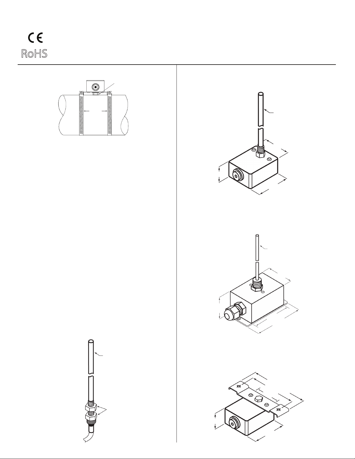
PIPE TEMPERATURE SENSORS
RoHS
Platinum RTD Sensors:
±0.1% @ 32°F (0°C), Alpha: 385 per DIN 43760
Nickel RTD Sensors (#2):
±0.5°C @ 0°C (32°F), 5,000 PPM/K T.C.R.
Nickel RTD Sensors (#4):
±0.5°F @ 70°F (21.1°C), 6,000 PPM/K T.C.R.
Balco RTD Sensors:
±0.5°F @ 70°F (21.1°C), 4,300 PPM/K T.C.R.
Thermistor Sensors:
±0.2°C interchangeability @ 77°F (25°C)
Operating Temperature:
-40°F to 210°F (-40°C to 100°C)
Ambient Temperature:
-40°F to 160°F (-40°C to 70°C)
Probe Material:
1/4" (6.3mm) O.D., 0.020" (0.5mm) wall, 304 Stainless Steel
Flange Material:
Galvanized Steel
Bulkhead Fitting:
Brass with poly compression sleeve
Plastic Enclosure:
Polycarbonate 30% glass filled, rated UL 94V-5-0
Steel NEMA-1 (IP-30):
18 Ga. Galvanized Steel
Steel NEMA-4 (IP-65):
18 Ga. Cold Rolled Steel, Powder coated
Warranty:
Five Years (Lifetime on Moisture Migration)
EMC Conformance:
EN 55022, 55024, 61000-3-3, 61000-4-2, 61000-4-3,
61000-4-4, 61000-4-5, 61000-4-6 & 61000-4-11
U.S. PATENT NO. 6457857, 6555748, 6599012, 7036224
ORDERING INFORMATION: TE-703-
INSTALLATION TEMP SENSOR PROBE
LENGTH
AImmersion style
with adapter
BPolycarb Plastic
Enclosure (IP-54)
CGalvanized Steel
Enclosure
(NEMA-1 / IP-30)
DPainted Steel
Enclosure
(NEMA-4 / IP-65)
A 4" (100 mm)
B6" (150 mm)
C8" (200 mm)
1 100-Ohm Platinum RTD
2 1,000-Ohm Nickel RTD
(5,000 PPM)
3 1,000-Ohm Platinum RTD
4 1,000-Ohm Nickel RTD
(6,000 PPM)
5 1,000-Ohm Balco RTD
7 10,000-Ohm NTC Thermistor
(Type III)
8 10,000-Ohm NTC Thermistor
(Carel)
10 3,000-Ohm NTC Thermistor
12 10,000-Ohm NTC Thermistor
(Type II)
13 5,000-Ohm NTC Thermistor
14 1,035-Ohm Silicon PTC
15 100,000-Ohm NTC Thermistor
16 10,000-Ohm NTC Thermistor
.........(Eliwell)
17 20,000-Ohm NTC Thermistor
18 2,252-Ohm NTC Thermistor
21 1,800-Ohm NTC Thermistor
ORDERING INFORMATION: TE-704-
ASurface Mount
Strap-On
BPolycarb Plastic
Enclosure (IP-54)
CGalvanized Steel
Enclosure
(NEMA-1 / IP-30)
DPainted Steel
Enclosure
(NEMA-4 / IP-65)
Examples:
TE-703-A-10-A-3: Immersion style with 1/2" adapter, 3,000 ohm thermistor & 4" probe.
TE-703-D-10-C-2: NEMA-4 enclosure, 3,000 ohm thermistor, 8" probe & 1/4" NPT brass fitting. Example: TE-704-C-1: NEMA-1 enclosure with 100 ohm Platinum RTD surface mount sensor.
ADAPTER
11/8" NPT
21/4"NPT
31/2" NPT
INSTALLATION TEMP SENSOR
1 100-Ohm Platinum RTD
2 1,000-Ohm Nickel RTD
(5,000 PPM)
3 1,000-Ohm Platinum RTD
4 1,000-Ohm Nickel RTD
(6,000 PPM)
5 1,000-Ohm Balco RTD
7 10,000-Ohm NTC Thermistor
(Type III)
8 10,000-Ohm NTC Thermistor
(Carel)
10 3,000-Ohm NTC Thermistor
12 10,000-Ohm NTC Thermistor
(Type II)
13 5,000-Ohm NTC Thermistor
14 1,035-Ohm Silicon PTC
15 100,000-Ohm NTC Thermistor
16 10,000-Ohm NTC Thermistor
.........(Eliwell)
17 20,000-Ohm NTC Thermistor
18 2,252-Ohm NTC Thermistor
21 1,800-Ohm NTC Thermistor