m&h Inprocess 40.01-TX User manual

m&h Inprocess Messtechnik GmbH xAm Langholz 11 xD-88289 Waldburg
Infrared Probe 40.01
-
TX/RX
www.mh
-
in
p
rocess.com
OPERATING INSTRUCTIONS
(Translation of the original operating instructions)
Page
System Components, Technical Data, Dimensions 1
Probe ON / OFF Angle, Transmitting / Receiving 2
Stylus Change, Battery Replacement, Optical Status Display 3
Aligning Stylus to Spindle Centre 4
Infrared Signal Range / Power Off Delay / Battery Life,
Maintenance, Cleaning Jets 5
Shank Mounting, HSK Shanks 6
SK Shanks, Coromant Capto Shanks
Tool Holder VDI 7
Other Shanks, THERMO-LOCK®Shanks,
Aligning probe in shank with 90° Adapter 8
Styli 9
Spare Parts, Accessories 10
BA4001-TX/RX-3010-WEST Subject to change without notice

1
Infrared Probe 40.01
-
TX/RX
Infrared Receiver
91.40-RX/TX/°C
91.30-RX/TX
Infrared Probe
40.01-TX/RX
System Components
Technical Data Dimensions
Probing Directions:
±
X;
±
Y; -Z
Max. Overtravel: XY
±
12,5°; Z –5mm
Probing Force Z = 7N
with 50mm Stylus: X/Y = 1N
Recommended 254mm/min –
Probing Speed: 2000mm/min
Power Supply: 1x3V Battery
Type CR2 (IEC)
Standby: 12 months
Alternative 1x3,6V Battery
Power Supply: Type ½ AA (IEC)
Material: Stainless steel
Weight without Shank: ca. 390g
Temperature: Operating: 10° - 50°C
Storage: 5° - 70°C
Repeatability: max. 2Sigma
±
1µm
with 50mm stylus at
254mm/min
Sealing: IP68: EN60529
(15 m) tested
Maximum
Probing Frequency: 30 Hz = 30 points / sec
Shock tested: in
±
X;
±
Y; -Z
50G for 7ms (5000 times)
Resonant
Frequency Test: Passed
M4 Stylus
Infrared
receiver unit
High Power
Infrared diodes
Stylus aligned
to spindle center
Customer specified
shank
Battery compartment
Cleaning jets

Infrared Probe 40.01
-
TX/RX
2
O
N
OF
F
0
V
>10VD
C
<1s
<1
,
5s
M-Code
Probe ON / OFF Angle – during ON / OFF
Transmitting / Receiving
= Receiving
= Transmitting
= Receiving
= Transmitting
Infrared Probe
40.01-TX/RX
Adjustable Range
≤1.6m (5.2´)
≤3.3m (10.8’)
≤4.0m (13.1´)
Infrared Receiver
91.40-RX/TX/°C
ON/Off Range
≤4.0m (13.1’)
alternative
Infrared Receiver
91.30-RX/TX
ON/OFF Adjustable Range
≤1.5m (4.9’)
≤2.2m (7.4´)
≤3.0m (9.8´)
ON/OFF Pro
c
edure
Infrared Probe 40.01
-
TX/RX
3
M
≈
2Nm
(
1.47 lbf.ft
)
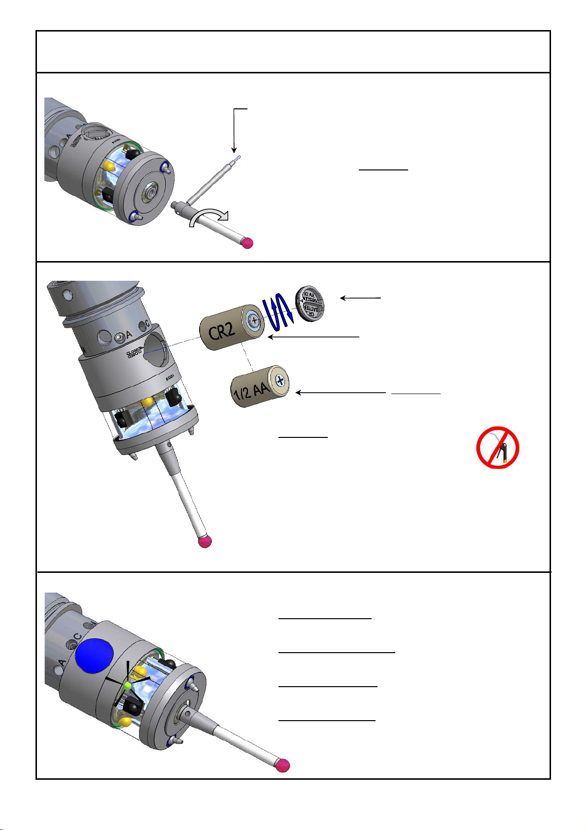
Stylus Change
Attention !
After changing the stylus:
eAlign stylus to spindle centre
eCalibrate probe
Battery Replacement
Attention !
eWipe probe clean and dry
before opening!
Do NOT use compressed
air to clean!
eTurn battery cover with bayonet lock to open and close !
eWhen closing the battery compartment check the
O-Ring for any damage !
eReplace empty battery immediately !
Optical Status Display
LED blinking green:
eProbe transmitting signal
LED blinking green / red:
eLow battery warning
LED blinking orange:
eStylus deflected
LED continuous red:
eWrong battery type
Alternative:
Battery 3,6V
Type ½ AA
Mounting pin
#0885
Battery Type CR2 (3V)
#3869
Battery cover #3920
with O-Ring 13x1 Viton #3549

Infrared Probe 40.01
-
TX/RX
4
Aligning Stylus to
Spindle Centre
1 Set „C“ Screws
- Loosen all "A" screws 2 turns
- Loosen the "C" screws
- Using the long end of the Hex key
tighten both "C" screws lightly
3Tighten „C“ Screws
- Tighten both “C” screws using the
short end of the Hex Key
5Retighten „C“ Screws
- Using the short end of the Hex Key
- Securely retighten both "C" screws
2Adjustment to <20µ
- Set dial gauge in front of the probe (see pict.)
- Turn the probe until the maximum deviation
is shown on the indicator
- Turn the "A" screws
half of the indicator reading
- Loosen the "A" screws that were
used 1 turn
- Repeat procedure
until runout is < 20µ
4Adjustment to <2µ
- Turn the probe until the maximum deviation
is shown on the indicator
- Turn the "A" screws
half of the indicator reading
- Loosen the "A" screws that were
used 1 turn
- Repeat procedure
until runout is < 2µ
6Set „A“ Screws against each other
- Set opposing „A“ screws (0° - 180°)
against each other
- Repeat with the other two opposing
„A“ screws (90 - 270°)
If the runout goes out
of adjustment:
- Turn the probe until the maximum deviation
is shown on the indicator
- Carefully loosen the „A“ screws
on the opposite side until the
runout is < 2µ
- Set the opposing „A” screws
against the newly adjusted
one
Hexagon key
AF2.5mm
#1346
Hexagon key AF2mm
#1097

Infrared Probe 40.01
-
TX/RX
5
±
30°
Infrared Signal Range / Power Off Delay / Battery Life
Infrared signal range:
There are 3 infrared range settings which can be selected: 1.6m – 3.3m – 4.0m.
A reduced range can be useful to ensure that nearby infrared systems are not interfered with.
A high range setting shortens the battery life.
Power off delay:
If the probe is not triggered within a given time, it is automatically shut off.
3 settings for the delay time are possible: 60s – 120s – 180s.
For removing the shank, see page 6
Attention !
eAfter removing the shank, wipe the probe
clean and dry !
Do NOT use compressed air to clean!
eEnsure the probe is turned off !
eAdjust the desired range !
eRemount the shank.
eAlign the stylus !
eCalibrate the probe !
Maintenance Cleaning Jets
Dirt can accumulate under the metal eyelid Cleaning the workpiece and the stylus tip
To clean : with through-spindle air.
eRemove service cover with eyelid and
conical spring by hand.
eClean probe and parts under flowing water.
eReplace parts and close probe by hand.
eCalibrate probe.
Attention !
eDo NOT use compressed air or high pressure
water to clean!
eDo NOT use any sharp tools!
(These could damage the inner seal)
Optional: Cleaning jets 40.01-Jets
Infrared Signal
Range
(Typical)
Power Off
Delay
Battery Life in Continuous Use
CR2 5%
usage
½ AA 5%
usage
0≤4.0m Infrared OFF 180h 130d 270h 190d
1≤4.0m 180s 180h 130d 270h 190d
2≤3.3m 180s 220h 145d 350h 210d
3≤1.6m 180s 290h 170d 440h 240d
4≤4.0m 120s 180h 130d 270h 190d
5≤3.3m 120s 220h 145d 350h 210d
6≤1.6m 120s 290h 170d 440h 240d
7≤4.0m 60s 180h 130d 270h 190d
8≤3.3m 60s 220h 145d 350h 210d
9≤1.6m 60s 290h 170d 440h 240d
Attention !
Only use through-
spindle air !
Pressure < 7bar
Do NOT use coolant !
Screwdriver
Service cover
#3240
Metall eyelid
#2906
Conical spring
#2931
Inner Seal
Factory Settings

t
Infrared Probe 40.01
-
TX/RX
6
Mounting the Shank
Removing the shank:
eRemove all „A“ and „C“ screws.
eRemove shank.
Assembling the shank:
eEnsure the O-Rings are properly seated!
eCarefully slide the shank onto the probe body. Align
the „C“ threads with the conical bores.
eInsert both clamping screws „C“ and tighten lightly.
eInsert adjustment screws „A“.
eAlign the stylus to spindle center.(see page 4)
eCalibrate the probe.
Probe with shank HSK Available Shanks: L: Order Number:
DIN69893-HSK-E25 69 (2.71”) 40.01-HSK25E
DIN69893-HSK-A32 86 (3.39”) 40.01-HSK32A
DIN69893-HSK-E32 86 (3.39”) 40.01-HSK32E
DIN69893-HSK-A40 86 (3.39”) 40.01-HSK40A
DIN69893-HSK-E40 86 (3.39”) 40.01-HSK40E
DIN69893-HSK-F40 86 (3.39”) 40.01-HSK40F
DIN69893-HSK-A50 86 (3.39”) 40.01-HSK50A
DIN69893-HSK-A50 116,5 (4.59”) 40.01-HSK50A-116,5
DIN69893-HSK-E50 92 (3.62”) 40.01-HSK50E
DIN69893-HSK-E50 116,5 (4.59”) 40.01-HSK50E-116,5
DIN69893-HSK-F50 92 (3.62”) 40.01-HSK50F
DIN69893-HSK-A63 86 (3.39”) 40.01-HSK63A
DIN69893-HSK-A63 116,5 (4.59”) 40.01-HSK63A-116,5
DIN69893-HSK-A63-70 120 (4.72”) 40.01-HSK63A-120
DIN69893-HSK-E63 116,5 (4.59”) 40.01-HSK63E
DIN69893-HSK-F63 121,5 (4.78”) 40.01-HSK63F
DIN69893-HSK-A80 121,5 (4.78”) 40.01-HSK80A
DIN69893-HSK-A100 92 (3.62”) 40.01-HSK100A
DIN69893-HSK-A100 121,5 (4.78”) 40.01-HSK100A-121,5
Kennametal KM63 121,5 (4.78”) 40.01-KM63
Kennametal KM80 121,5 (4.78”) 40.01-KM80
Other shanks upon request
C = Clamping screw AF2.5mm (2x)
#1351 M=2 Nm (1.47 lbf.ft)
A
= Adjustment screw DIN913 M4x8 (AF2mm) (4x)
#1352 M=1.5 Nm (1.1 lbf.ft)
Hexagon Key
A
F2mm #1097 / AF2.5mm #1346
Clamping screw „C“
in conical bore
Adjustment screw „A“ in thread
Shank
Probe
O-Ring 17x1 Viton
#3239
Not included

Infrared Probe 40.01
-
TX/RX
7
Probe with shank SK
Available Shanks: L: Order Number:
DIN69871-SK30 94,5 (3.72”) 40.01-SK30
DIN69871-SK30-Mube 94,5 (3.72”) 40.01-SK30-Mube
DIN69871-SK40 96,5 (3.8”) 40.01-SK40
DIN69871-SK40-70 120 (4.72”) 40.01-SK40-120
DIN69871-SK50 96,5 (3.8”) 40.01-SK50
DIN69871-SK60 116,5 (4.59”) 40.01-SK60
BT30 77 (3.03”) 40.01-BT30
BT30 94,5 (3.72”) 40.01-BT30-94,5
BT30 127 (5”) 40.01-BT30-127
BT30 152 (5.98”) 40.01-BT30-152
BT30 177 (6.97”) 40.01-BT30-177
BT40 96,5 (3.8”) 40.01-BT40
BT40-70 120 (4.72”) 40.01-BT40-120
BT50 111,5 (4.39”) 40.01-BT50
CAT40 96,5 (3.8”) 40.01-AN40
CAT40-70 120 (4.72”) 40.01-AN40-120
CAT50 96,5 (3.8”) 40.01-AN50
Other shanks upon request
Probe with shank Coromant Capto
Available Shanks: L: Order Number:
Coromant Capto C4 86 (3.39”) 40.01-C4
Coromant Capto C5 86 (3.39”) 40.01-C5
Coromant Capto C5 121,5 (4.78”) 40.01-C5-121,5
Coromant Capto C5-90° 102,5 (4”) 40.01-C5-90°
Coromant Capto C6 92 (3.62”)) 40.01-C6
Coromant Capto C6 121,5 (4.78”) 40.01-C6-121,5
Coromant Capto C6-90° 102,5 (4”) 40.01-C6-90°
Coromant Capto C8 92 (3.62”) 40.01-C8
Coromant Capto C8 121,5 (4.78”) 40.01-C8-121,5
Coromant Capto C8-90° 102,5 (4”) 40.01-C8-90°
Other shanks upon request
Probe with tool holder VDI Available Tool holders: L: Order Number:
VDI 16 75,0 (2.95”) 40.01-VDI16
VDI 16-90° 56,0 (2.2”) 40.01-VDI16-90°
VDI 20 75,0 (2.95”) 40.01-VDI20
VDI 20-90° 56,0 (2.2”) 40.01-VDI20-90°
VDI 25 75,0 (2.95”) 40.01-VDI25
VDI 25-90° 56,0 (2.2”) 40.01-VDI25-90°
VDI 30 79,0 (3.11”) 40.01-VDI30
VDI 30-90° 60,0 (2.36”) 40.01-VDI30-90°
VDI 40 98,5 (3.38”) 40.01-VDI40
VDI 40-90° 79,5 (3.13”) 40.01-VDI40-90°
VDI 50 98,5 (3.38”) 40.01-VDI50
VDI 50-90° 79,5 (3.13”) 40.01-VDI50-90°
VDI 60 98,5 (3.38”) 40.01-VDI60
VDI 60-90° 79,5 (3.13”) 40.01-VDI60-90°
VDI 80 98,5 (3.38”) 40.01-VDI80
VDI 80-90° 79,5 (3.13”) 40.01-VDI80-90°
Other tool holders upon request
Not
included
Not
included
Not included
91.00-SWV
not
included
Infrared Probe 40.01
-
TX/RX
8
up
down
±5° down
up
Probe with other shanks
Available Shanks: L: Order Number:
D20-D8-L25-B 65 (2.56”) 40.01-D8-L25
D20-D32-L100-B 62 (2.44”) 40.01-D32-L100
NIKKEN-NC5-46 115,5 (4.55”) 40.01-NC5-46
NIKKEN-NC5-63 115,5 (4.55”) 40.01-NC5-63
D20-Erowa-ITS 91 (3.58”) 40.01-ITS
Probe with shank THERMO-LOCK®(patented)
Available Shanks: L: Order Number:
DIN69893 HSK-E32 86 (3.39”) 40.01-HSK32E-TI
DIN69893 HSK-E40 86 (3.39”) 40.01-HSK40E-TI
DIN69893 HSK-E50 92 (3.62”) 40.01-HSK50E-TI
DIN69893 HSK-A63 92 (3.62”) 40.01-HSK63A-TI
Patented THERMO-LOCK®Technology prevents thermal
expansion of the HSK and heat transfer from the spindle to the
probe. This ensures that the probe delivers stable, precise results
even by large temperature differences between the spindle and
the HSK.
Aligning probe in shank with 90°Adapter
Procedure:
eLoosen adjustment screws „A“ (4x) then tighten lightly.
eLoosen clamping screws „C“ (2x) then tighten lightly.
eAdjust the angular position of the probe using cylinder screw AF4mm to (±5°).
eTighten the clamping screws „C“ (2x).
eAlternately tighten the adjustment screws „A“ (4x).
eCalibrate probe.
Hexagon key AF4mm
#3489
Not included
Not
included
Air Nozzle with rotary joint
for tool holder VDI
91.00-SWV
90° Adapter for
Tool Holder VDI
D2
0
-VDI
-
90
°

Infrared Probe 40.01
-
TX/RX
9
M4-Styli, Shaft-Ø7
All styli with ceramic shaft
Order Number:
91.00-T103/6-KE-M4
(Ruby ball)
91.00-T83/6-KE-M4
(Ruby ball)
91.00-T53/6-KE-M4
(Ruby ball)
91.00-T103/6-KE-M4-Si
(Silicon nitride ball)
91.00-T53/6-KE-M4-Si
(Silicon nitride ball)
91.00-TV30-KE-M4
(Stylus extension)
M4-Styli, Shaft-Ø5
All styli with ruby ball
Order Number:
91.00-TK-ST-M4
(5-way Stylus centre)
91.00-T20/2-HM-M4
(Tungsten carbide shaft)
91.00-T20/3-HM-M4
(Tungsten carbide shaft)
91.00-T20/4-HM-M4
(Tungsten carbide shaft)
91.00-T20/5-ST-M4
(Steel shaft)
91.00-T20/6-ST-M4
(Steel shaft)
91.00-T20/7-ST-M4
(Steel shaft)
91.00-T20/8-ST-M4
(Steel shaft)
M3-Styli, Shaft-Ø4
All styli with ruby ball and tungsten carbide
shaft
Order Number:
91.00-TA-M4/M3
(Stylus
Adapter)
21.00-T20/1-HM-M3
21.00-T20/2-HM-M3
21.00-T20/3-HM-M3
21.00-T20/4-HM-M3
21.00-T20/5-HM-M3
21.00-T20/6-HM-M3
21.00-T30/2-HM-M3
21.00-T30/3-HM-M3
21.00-T30/4-HM-M3
21.00-T30/5-HM-M3
21.00-T30/6-HM-M3
Other styli available upon request.

10
Infrared Probe 40.01
-
TX/RX
Spare Parts, Accessories
Probe Parts
Order Number Description
#3869 Battery Type CR2 (3V)
#3920 Battery cover
#3549 O-Ring 13x1 Viton
for battery cover
#1351 Clamping screw AF2.5mm
#1352 Adjustment screw DIN913 M4x8 (AF2mm)
#3240 Service cover
#3455 O-Ring 16x1 Viton
for service cover
#2906 Metal eyelid
#2931 Conical spring
#3239 O-Ring 17x1 Viton
for Shank
Tools
Order Number Description
#0885 Mounting pin
#1346 Hexagon key AF2.5mm
#1097 Hexagon key AF2mm
#3489 Hexagon key AF4mm
#3079 Dial gauge

Infrared Probe 40.01
-
TX/RX
11
Spare Parts, Accessories
Accessories
Order Number Description
40.01-TB
Toolbox:
1x Mounting Pin #0885
2x Hexagon key AF2mm #1097
1x Hexagon key AF2.5mm #1346
91.00-SWV Air Nozzle with rotary joint
for VDI shanks
D20-VDI-90° 90°Adapter for Tool Holder VDI
#3611 Storage box
This manual suits for next models
1
Table of contents
Popular Measuring Instrument manuals by other brands


SUTO
SUTO S520 Instruction and operation manual

PCB Piezotronics
PCB Piezotronics IMI SENSORS 646B00 Assembly, installation and operating manual

Haug
Haug Test Line Static Meter I operating instructions

Bartec
Bartec TECH600PRO user guide

3M
3M Stormscope Series 2 instruction manual

B&K
B&K 2250 Light user manual