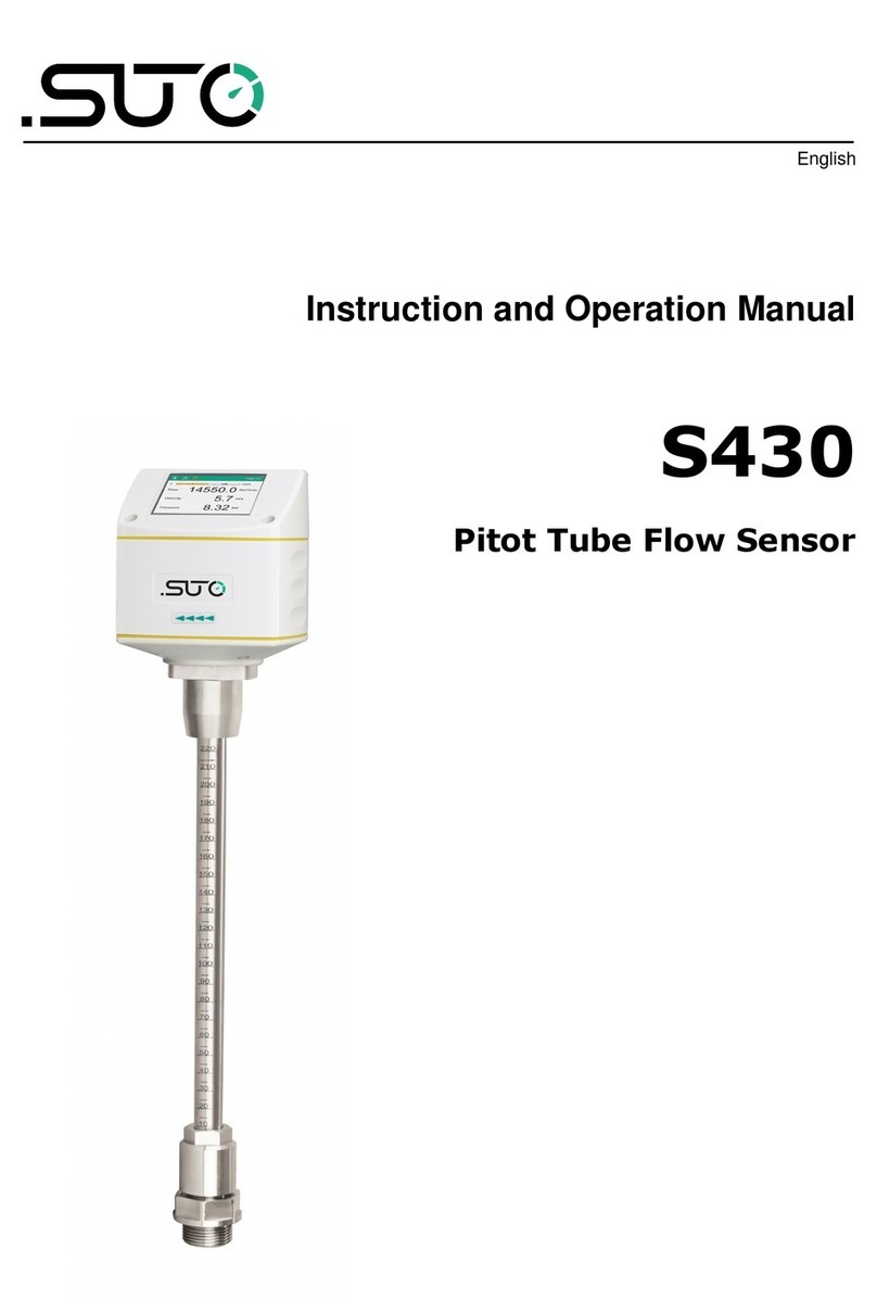
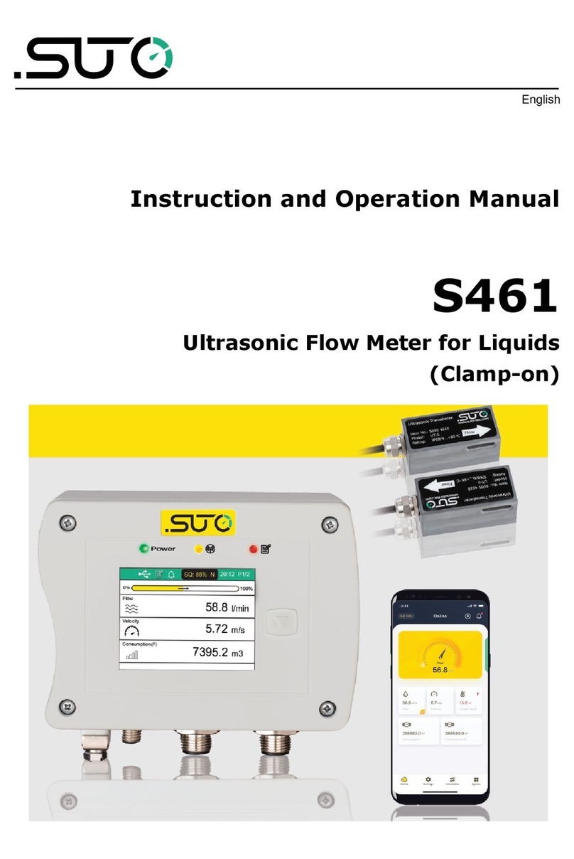
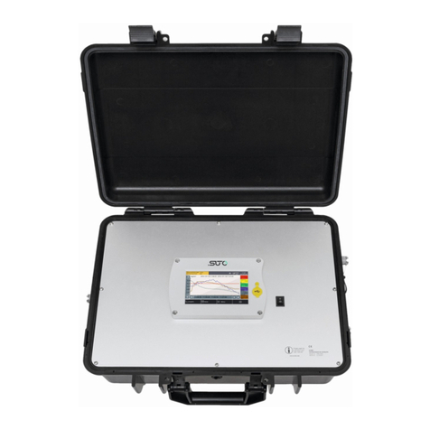
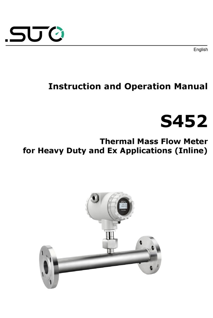
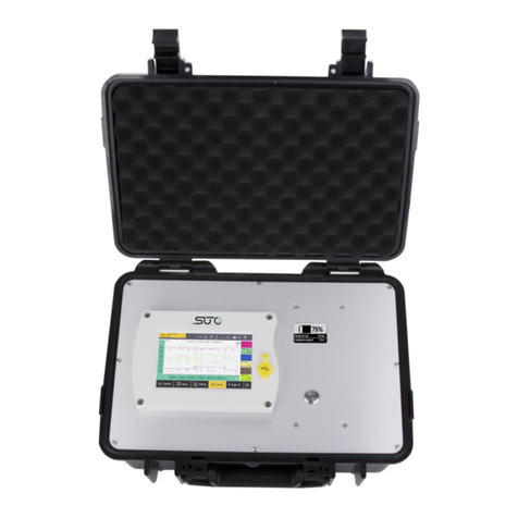
SUTO S520 Manual

English
Instruction and operation manual
S520
Portable Dew Point Meter

Dear Customer,
Thank you for choosing our product.
Please read the operating instructions in full and carefully observe it
before starting up the device. The manufacturer cannot be held liable
for any damage that occurs as a result of non-observance or non-
compliance with this manual.
Should the device be tampered with in any manner other than a
procedure that is described and specified in the manual, the warranty is
cancelled and the manufacturer is e empt from liability.
The device is designed e clusively for the described application.
SUTO offers no guarantee for the suitability for any other purpose.
SUTO is also not liable for consequential damage resulting from the
delivery, capability or use of this device.
2 S520

Table of contents
1 Safety instructions......................................................................5
2 Registered trademarks.................................................................7
3 Application.................................................................................8
4 Features....................................................................................8
5 Technical data.............................................................................9
5.1 General................................................................................9
5.2 Electrical data.....................................................................10
5.3 Accuracy ...........................................................................10
6 Dimensional drawing..................................................................11
7 Installation...............................................................................12
7.1 Installation procedure..........................................................13
7.2 Electrical connection............................................................14
7.3 Replacing the sensor unit......................................................15
8 Operation.................................................................................16
8.1 Buttons and connectors........................................................16
8.2 Symbols on screen..............................................................17
8.3 Home screen ......................................................................18
8.3.1 Home Screen operations.................................................18
8.4 Menu.................................................................................19
8.4.1 Device settings..............................................................22
8.4.2 Sensor Settings.............................................................23
8.4.3 Logger.........................................................................24
8.4.4 Files.............................................................................24
8.4.5 Device info....................................................................25
8.4.6 Service info...................................................................26
8.4.7 Site information.............................................................26
8.4.8 Wireless printer.............................................................27
8.5 Graph................................................................................27
8.6 Print files............................................................................28
8.7 Smart features....................................................................29
8.8 E port logger files to a PC.....................................................30
8.9 Update the device Firmware..................................................30
9 Application software .................................................................32
9.1 S4A...................................................................................32
10 Optional accessories................................................................33
10.1 Wireless printer CS2 (A1372)..............................................33
10.1.1 Paper loading..............................................................33
10.1.2 Basic operations..........................................................34
10.2 Measuring chambers for the S520........................................35
10.2.1 Standard measuring chamber (A699 3500).....................35
10.2.2 By-pass measuring chamber (A699 3501).......................35
S520 3

11 Calibration..............................................................................36
11.1 Dew point calibration..........................................................36
11.2 Pressure calibration ...........................................................36
12 Maintenance...........................................................................36
13 Disposal or waste....................................................................37
4 S520

1 Safety instructions
Please check if this instruction manual matches the
product type.
Please observe all notes and instructions indicated in this
manual. It contains essential information which must be
observed before and during installation, operation, and
maintenance. Therefore this instruction manual must be read carefully
by the technician as well as by the responsible user/qualified personnel.
This instruction manual must be available at the operation site of the
dew point meter at any time. In case of any obscurities or questions,
regarding this manual or the product, please contact the manufacturer.
ARNING!
Compressed air!
Any contact with quickly escaping air or bursting
parts of the compressed air system can lead to
serious injuries or even death!
•Only use pressure tight installation material.
•Avoid that persons get hit escaping air or bursting parts of the
instrument.
•The system must be pressure-less during maintenance work.
ARNING!
Voltage used for supply!
Any contact with energized parts of the product may
lead to an electrical shock, which can lead to serious
injuries or even death!
•Consider all regulations for electrical installations.
•The system must be disconnected from any power supply during
maintenance work.
•Any electrical work on the system is only allowed by authorized
qualified personal.
S520 5

1 Safety instructions
ATTENTION!
Permitted operating parameters!
Observe the permitted operating parameters. Any
operation exceeding this parameters can lead to
malfunctions and may lead to damage on the
instrument or the system.
•Do not e ceed the permitted operating parameters.
•Make sure the product is operated in its permitted limitations.
•Do not e ceed or undercut the permitted storage and operating
temperature and pressure.
General safety instructions
•It is not allowed to use the product in e plosive areas.
•Please observe the national regulations before/during installation
and operation.
Remarks
•It is not allowed to disassemble the product.
•Always use a spanner to mount the product properly.
ATTENTION!
Measurement values can be affected by malfunction!
The product must be installed properly and
frequently maintained. Otherwise, it may lead to
wrong measurement values, which can result in
wrong results.
Storage and transportation
•Make sure that the transportation temperature of the dew point
meter is between -30 ... +70°C.
•For transportation it is recommended to use the packaging that
comes with the sensor.
•Please make sure that the storage temperature of the sensor is
between -20 ... +50°C.
•Avoid direct UV and solar radiation during storage.
•For the storage the humidity must be <80% rH with no
condensation.
6 S520

2 Registered trademarks
SUTO®
Registered trademark of SUTO iTEC
MODBUS®
Registered trademark of the Modbus Organization, Hopkinton, USA
HART®
Registered trademark of the HART Communication Foundation, Austin,
USA
PROFIBUS®
Registered trademark of the PROFIBUS User Organization, Karlsruhe,
Germany
S520 7

3 Application
3 Application
The S520 is a dew point meter that is designed to monitor the dew
point in the industrial application within the permissible operating
parameters. These parameters can be found in the Technical data
chapter on page 9.
The S520 can measure and display the following values for compressed
air or gas:
•Dew point, default unit: °C Td
•Humidity, default unit: °C Td
•Temperature, default unit: °C
•Pressure, default unit: bar (g)
The S520 dew point meter is mainly used in compressed air systems in
industrial environments. It is not developed to be used in e plosive
areas. For the use in e plosive areas please contact the manufacturer.
4 Features
•Measures dew point, temperature, humidity, and pressure
•Two sensor solutions available:
◦Sensor A: Standard sensor unit with a range of
-100 … +20°C Td
◦Sensor B: Economic sensor unit with a range of
-50 … +50°C Td
•Smart dew point prediction
•Integrated pressure sensor
•Modern colour touch screen interface
•Data logger, USB interface, and Bluetooth connection to a portable
printer
•Measuring/parking chamber, designed for fast sensor response
•Application software included
•Integrated camera for more elegant reports
•ISO8573-1 Class indication
8 S520

5 Technical data
5 Technical data
5.1 General
Parameters Standard unit dew point: °C Td
Standard unit temperature: °C
Other units: °F, K
Standard unit humidity: % rH
Standard unit pressure: bar(g), MPa(g)
Principle of measurement Capacitive method, Oscillating crystal
Sensor Sensor A: QCM + Polymer
Sensor B: Polymer
Temperature: Pt100
Pressure: Piezo resistive type (only with
Sensor A1370)
Measuring medium Air, CO2, N2, Argon (CO2 measurements with
the A1371 module are limited to -40 °C Td)
Measuring range Sensor A: -100 … +20°C Td
Sensor B: -50 … +50°C Td
Pressure: 0 … 1.5 MPa (g)
Temperature: -30 … +50°C
Operating temperature Medium: -30 … +50°C
Ambient: 0 … +40°C
Operating pressure -0.1 … 1.6 MPa (g) *
Humidity Medium: 0 … 90% rH
Ambient: 0 … 80% rH
Casing material PC + ABS
Protection class IP65
Dimensions See dimensional drawing on page 11
Display 3.5” color LCD touch screen
Weight 2.7 kg complete set in transport case
Camera 5.0 megapi els (only with smart features
option)
Data Logger Integrated mass storage, 100 Million values
Process connection G1/2” for direct sensor connection,
S520 9

5 Technical data
Measuring chamber with 6 mm hose quick
coupling
* At least 0.3 MPa(g) is needed for the measuring chamber supplied with
the instrument. For low-pressure measuring below 0.3 MPa(g), choose
the optional bypass measuring chamber A699 3501.
5.2 Electrical data
Power supply USB charger: 5 V, 2 A
Connector: USB-C
Battery Operating time on one charge: ~8 h
Charging time until full: ~3 h
5.3 Accuracy
Accuracy Dew point:
± 1 °C Td (0 … 20°C Td)
± 2 °C Td (-60 … 0 / +20 … +50°C Td)
± 3 °C Td (-100 … -60°C Td)
Temperature:
± 0.3 °C
Pressure:
0.5 % FS
Repeatability ± 0.5°C
Stated accuracy at Ambient/process temperature: 23°C ± 3°C
Ambient humidity: 0 … 80% rH, no
condensation
10 S520

Installation
7 Installation
Please make sure that all components listed below are included in your
package.
Qty Description Item No.
1 S520 Handheld meter with data logger
- Measuring chamber with parking function
- USB-OTG memory stick
- 1.5 m TFE hose 6 mm with a quick coupling at
one end
- Certificate of calibration
- USB charger with USB-C cable
- Transport case
P600 0520
1 Sensor unit A or A1370 or
Sensor unit B A1371
1 Parking / Measuring chamber
(included in set P600 0520)
A699 3500
1 1.5 m PTFE hose with a quick coupling at one
end
(included in set P600 0520)
A554 0003
1 USB charger with USB cable
(included in set P600 0520)
A554 0018
1 Transport case
(included in set P600 0520)
A554 0019
1 USB-OTG Memory Stick with the USB-A and USB-
C connectors
(included in set P600 0520)
A554 0124
12 S520

Installation
7.1 Installation procedure
The following steps e plain the procedure of an appropriate installation.
1. Make sure that the teflon hose is dry
and clean.
Attention:
Wet and contaminated hoses can
negatively affect the measurement and
must be replaced with a dry and clean
one.
2. Connect the teflon hose to the
measuring chamber.
3. Connect the quick coupling at the other
end of the teflon hose to the process.
S520 13

Installation
5. Turn the handle on the chamber to the
“Measuring” position.
Note: The parking measuring chamber is
mounted permanently on the sensor head
to keep the sensor dry. To measure, the
handle on the chamber must be turned
into the “Measuring” position.
After finishing the measurement, please
turn it to the “Park” position.
6. Turn on the device.
7. Start to measure using the touch screen. For more information, see
Chapter 8 Operation.
7.2 Electrical connection
Please charge the dew point meter if the battery is low. To do so, use
the charger that is included in the delivery package.
1. Connect the USB cable to the device and the charger.
2. Plug in the charger to your AC supply outlet.
The device starts to indicate the charging progress. Always try to
charge to 100%.
14 S520

Installation
7.3 Replacing the sensor unit
For service or calibration, the sensor units can be e changed easily.
Before e changing the sensor units, please make sure that the new one
has the dew point range that matches your need:
•Sensor A: -100 … +20 °C Td
•Sensor B: -50 … +50 °C Td
To e change the sensor units, follow the below steps:
1. Open the two screws at the back of
the instrument.
2. Pull the sensor unit together with the
measuring chamber out of the main unit.
3. Screw the measuring chamber off the
sensor unit.
4. Screw the measuring chamber onto
the new sensor unit.
5. Insert the new sensor unit together
with the measuring chamber back to the
sensor unit.
6. Tighten the two screws.
S520 15

Installation
ATTENTION!
Do not remove or touch the sinter cap on the sensor
unit. The sinter cap protects the sensor element from
dust and particles. rong handling may effect or
even destroy the sensitive sensor element!
8 Operation
8.1 Buttons and connectors
Logger Menu To access the Logger menu to set up the logging rate
and mode.
Power On/off To turn on or off, keep the button pressed for >3 sec.
Measurement To quickly record a file of the current measurements for
later printing.
16 S520
Logger Menu Power On/off Measurement

8 Operation
8.2 Symbols on screen
Indicates that the sensor unit calibration is e pired
and needs a calibration.
Please contact your supplier or the manufacturer for a
calibration service.
Indicates that the device is currently connected to a
PC or to a USB-OTG memory stick or the OTG function
is enabled.
Indicates the logger state.
•“Logger: Stopped” indicates that the logger is
currently not running.
•“Logger: Started” indicates that the logger is
running and recording the measurement data.
Indicates that a wireless printer is connected to the
device.
Shows the current device time.
Indicates the battery capacity of the device.
It also indicates whether the battery is draining or is
being charged.
S520 17
USB-C connector
For data transfer and device
charging

8 Operation
8.3 Home screen
8.3.1 Home Screen operations
Button Function
To open the device menu.
See 8.4 Menu on page 19 for a detailed
description of the menu.
To enter the graph view.
See 8.5 Graph on page 27 for a detailed
description of the menu.
Shows the measured dew point value in
the selected unit.
The predicted dew point is available only
if the S520 is ordered with smart
features.
To change the unit of the dew point,
press this pane, and a pop-up window
appears for you to change the unit.
18 S520

8 Operation
Shows the Class according to the ISO
8573-1.
Measured indicates the Class of the
actual measured value.
Predicted indicates the Class of the
predicted dew point.
Target indicates the e pected Class that
you set.
To set the Target class, press this pane.
Shows the alternative humidity unit.
To change the unit, press the value, and
a pop-up window appears with a list of
alternative units for you to select.
Shows the measured pressure.
To change the unit, press the value, and
a pop-up window appears with a list of
alternative units for you to select.
Shows the measured temperature.
To change the unit, press the value, and
a pop-up window appears with a list of
alternative units for you to select.
8.4 Menu
The device menu offers different operations, such as connecting a
printer, reading device information, and many more.
Below is the tree structure of the device menu. The following
sections provide detailed description for each menu.
S520 19
Table of contents
Other SUTO Measuring Instrument manuals
Popular Measuring Instrument manuals by other brands

Extech Instruments
Extech Instruments HD450-NIST user guide

BANTE inststruments
BANTE inststruments 210 instruction manual

Azbil
Azbil MagneW Plus+ Series user manual

ThermoWorks
ThermoWorks BlueTherm IR operating instructions

Siemens
Siemens SITRANS L APPLICATION EXAMPLES

Dickey-John
Dickey-John C-2000 manual