INTRODUCTION
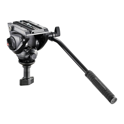
Lightweight head ideal for video cameras up to 4 kg.
KEY FEATURES
• Quick release plate with secondary security and antirotation pin
• Sliding top plate for camera balancing
• Pan and tilt movements with locking knobs
• Spirit level
• Built-in balance spring to help to support the camera weight
SET UP
The head is supplied with pan bar “A” not fitted. To fit the pan bar to the head at point “B”,
release the locking knob “C” push the end of the bar in to the fitting and lock when desired
position required.
ASSEMBLING HEAD ON TRIPOD
Assemble the head on the tripod using 3/8” female thread “E”.
The top plate on Manfrotto tripods are equipped with three set screws “F” which clamp
against the base of the head to ensure effective and secure locking.
REMOVE QUICK RELEASE PLATE FROM HEAD
Open the locking lever “H” as shown in figure 2 and extract the plate “G”
ASSEMBLING CAMCORDER ON PLATE
If your camcorder has a hole for a VHS pin, you will need to move pin “P” (fig. 1) from hole
“G” to hole “X”. Push the pin out from above to move it. If the camcorder doesn’t have
the VHS pin hole, simply remove the pin “P”. Fix the camcorder onto plate “G” (fig. 3) by
screwing home camera screw “M” into the camera’s threaded hole WITHOUT APPLYING
FORCE, using the ring “Q”.
Before fully locking, align the camcorder lens with pin “P” if appropriate, or with the
“LENS” marking on the camera plate “G”.
Please ensure you have securely locked the camcorder on to the release plate before use.
MOUNTING THE CAMERA ON THE HEAD
Open the locking lever “H” as shown in figure 4 and insert the camera plate “G”, then
release the locking lever “H” and push it in the locking position.
Please ensure that plate “G” is fully locked by pushing lever “H” and checking that the
camera is fitted securely to the head.
Hold the camcorder during the follow operation to prevent it from slipping backwards
and forwards.
BALANCING THE CAMERA ON THE HEAD &
The head is supplied with sliding top “S” (fig. 5) for balancing the camera:
- level the head on the tripod using as a reference the spirit level “K” (fig. 1)
- release the lever “L” (fig. 5)
- slide the camcorder backwards and forwards until you find the position in which it
remains still in horizontal position
- lock the lever “L”
The head is supplied with graduated scale “R” and index “Q in order to remember the
balancing position for each camcorder used.
Note: The head is provided with built-in balance spring to help to support the camera
weight. It has a balance power corresponding to a camera load of 1,2 kg (2,5 bs) even if
the head is able to support camera loads up to 4kg (8,8 lbs)
USE
The head features 360° pan and vertical tilt (+75° / -70°) which are controlled using the pan
bar “A”.
The pan movement can be locked using knob “D”.
The tilt movement can be locked using knob “N”.
The lever on the ratchet knobs “C” and “D” can be repositioned as required without
effecting the lock itself. Simply pull the lever outward, rotate as desired and release the
lever and it will automatically locate in the adjusted position.
The head is supplied with spirit level “K” for levelling (fig. 1).
1
1
2
3
4
1 5
1
INTRODUCTION
Rotule très légère conçue pour les caméscopes n’excédant pas 4 kg.
CARACTÉRISTIQUES PRINCIPALES
• Plateau rapide avec levier de sécurité secondaire et ergot VHS
• Plateau supérieur coulissant pour l’équilibrage du caméscope
• Mouvement panoramique et de bascule avec boutons de blocage séparés
• Niveau à bulle
• Ressort de contre-balancement intégré pour un meilleur support du poids de l’équipement
INSTALLATION
La rotule est fournie avec un levier panoramique “A” non monté. Pour fixer le levier
panoramique à la rotule au niveau du point “B”, desserrez le bouton de blocage “C”,
insérez l’extrémité du levier panoramique dans la bague de fixation et bloquez-le dans la
position souhaitée.
FIXATION DE LA ROTULE AU TRÉPIED
Fixez la rotule au trépied en vissant la vis 3/8” du trépied dans le filetage “E” de la rotule.
La base supérieure des trépieds Manfrotto est équipée de trois vis “F” qui, vissées à la
base de la rotule, permettent un verrouillage encore plus sûr et efficace.
RETRAIT DU PLATEAU RAPIDE DE LA ROTULE
Ouvrez le levier de blocage “H” tel qu’illustré à la figure 2 et retirez le plateau “G”.
FIXATION DU CAMÉSCOPE AU PLATEAU
Si la caméra est dotée de l’emplacement pour l’ergot VHS, vous devez alors retirez l’ergot
“P” (fig. 1) de la position “G” en le dévissant et le replacer à la position “X”. Si la caméra
n’est pas dotée de l’emplacement pour l’ergot VHS, retirez simplement l’ergot “P” en le
dévissant.
Fixez le caméscope au plateau rapide “G” (fig. 3) en vissant la vis de fixation “M” dans
l’orifice fileté du caméscope SANS FORCER, en vous aidant pour cela de l’anneau “Q”.
Avant de bloquer ce montage, alignez l’objectif avec l’ergot “P” si c’est possible, ou avec
l’inscription “LENS” du plateau “G” le cas échéant.
Assurez-vous que le caméscope est parfaitement fixé au plateau rapide avant utilisation.
FIXATION DU CAMÉSCOPE À LA ROTULE
Ouvrez le levier de blocage “H” tel qu’illustré à la figure 4 et insérez le plateau rapide “G”.
Relâchez ensuite le levier de blocage “H” et appuyez dessus afin qu’il se place en position
de blocage.
Assurez-vous que le plateau rapide “G” est correctement bloqué en appuyant sur le levier
“H” et vérifiez que le caméscope est parfaitement fixé à la rotule.
IMPORTANT ! Tenez le caméscope pendant cette opération afin de l’empêcher de
glisser vers l’avant ou l’arrière.
FIXATION DU CAMÉSCOPE À LA ROTULE ET
La rotule est livrée avec une base coulissante “S” permettant d’équilibrer le caméscope :
- mettez la rotule à niveau sur le trépied à l’aide du niveau à bulle “K” (fig. 1)
- desserrez le bouton de blocage “L” (fig. 5)
- faites coulisser le caméscope vers l’arrière et vers l’avant jusqu’à ce que vous trouviez
la position dans laquelle il se maintient correctement à l’horizontale
- resserrez le bouton de blocage “L”
La rotule est dotée d’une échelle graduée “R” et d’un repère “Q” vous permettant de
retenir le point d’équilibre de chaque caméscope utilisé.
Remarque : La rotule est également équipée d’un ressort de contre-balancement intégré
pour un soutien encore plus fiable du caméscope.
Pour optimiser l’équilibrage de la camera en position, la rotule est dotée d’un ressort de
contre-balancement ayant une capacité de charge de 1,5 kg (2,5 lbs) bien que la rotule
supporte un poids de 4 kg (8,8 lbs) maximum.
UTILISATION
Le levier panoramique “A” permet un mouvement panoramique de 360° et une bascule
avant/arrière de +75° à –70° de la rotule. Le mouvement panoramique se bloque à l’aide
du bouton “D”, tandis que le mouvement de bascule se bloque à l’aide du bouton “N”.
Par ailleurs, les boutons “C” et “D” sont indexés de façon à pouvoir être positionnés
différemment sans que cela ait d’incidence sur leur fonction de blocage.
Tirez le bouton vers vous, tournez-le dans la position souhaitée puis relâchez-le et il se
mettra automatiquement dans cette nouvelle position.
La rotule est dotée d’un niveau à bulle “K” pour une mise à niveau précise (fig. 1).
1
1
2
3
4
1 5
1
INTRODUZIONE
Testa leggera, ideale per videocamere fino a 4 Kg.
CARATTERISTICHE PRINCIPALI
• Piastra a sgancio rapido con sicurezza secondaria e piolino antirotazione VHS
• Piastra superiore scorrevole per bilanciamento delle videocamera
• Movimenti in panoramica ed inclinazione con manopole di blocco
• Livella a bolla
• Molla precaricata incorporata, per contribuire a supportare il peso della videocamera
PREPARAZIONE
La testa è fornita con la leva di comando “A” non inserita. Per inserire la leva di
comando nella posizione “B” sulla testa, allentare la leva di blocco “C”, inserire
l’estremità della leva nell’apposita sede e bloccarla una volta raggiunta la posizione
desiderata.
MONTAGGIO DELLA TESTA SUL TREPPIEDE
Montare la testa sul treppiede tramite l’attacco femmina “E” da 3/8”.
I dischi di fissaggio dei treppiedi Manfrotto sono dotati di tre grani “F” da serrare contro
la base della testa per assicurarne un bloccaggio efficiente e sicuro.
RIMOZIONE DELLA PIASTRA RAPIDA DALLA TESTA
Allentare la leva di blocco “H” ed estrarre la piastra “G” come mostrato in figura 2.
MONTAGGIO DELLA VIDEOCAMERA SULLA PIASTRA
Se la vostra videocamera dispone dell’apposito alloggiamento per il pin anti-rotazione
“P”, rimuovere il pin “P” (fig. 1) dalla posizione “G” e spostarlo nella posizione “X”. Se
la videocamera non dispone dell’apposito alloggiamento per il pin anti-rotazione “P”,
occorre semplicemente toglierlo.
Fissare la videocamera alla piastra “G” (fig. 3) avvitando a fondo la vite “M” nel
foro filettato alla base della videocamera SENZA APPLICARE FORZA ECCESSIVA,
servendosi dell’anello “Q”.
Prima di arrivare al bloccaggio finale, allineare l’obiettivo della videocamera col piolino
“P” se presente, o con la scritta “LENS” sulla piastra “G”.
Prima dell’uso occorre assicurarsi che la videocamera sia fissata saldamente alla
piastra rapida.
MONTAGGIO DELLA VIDEOCAMERA SULLA TESTA
Aprire la leva di blocco “H” come indicato in figura 4 ed inserire la piastra con la
videocamera “G”, quindi rilasciare la leva “H” accompagnandola in posizione di blocco.
Assicurarsi che la piastra “G” sia ben bloccata premendo la leva di blocco “H” e
controllando che la fotocamera sia saldamente fissata alla testa.
IMPORTANTE: Durante l’operazione seguente reggere la videocamera per
evitarne lo scivolamento in avanti o all’indietro.
BILANCIAMENTO DELLA VIDEOCAMERA SULLA TESTA E
La testa è dotata di piastra superiore “S” scorrevole per il bilanciamento ottimale della
videocamera:
- livellare la testa sul treppiede usando come riferimento la livella bolla “K” (fig. 1)
- sbloccare la leva “L” (fig. 5)
- fare scorrere la videocamera in avanti o all’indietro fino a trovare la posizione nella
quale rimane in equilibrio in posizione orizzontale
- bloccare la leva “L”
La testa è dotata di scala graduata “R” ed indice “Q” come riferimento per la posizione
di bilanciamento di ogni videocamera in uso.
Nota: La testa è dotata di molla precaricata per aiutare a reggere il peso della
videocamera. Questa molla esercita una forza corrispondente ad un videocamera da
1,2 Kg, anche se la testa può accettare videocamere fino a 4 Kg.
USO
La testa dispone di movimento panoramico di 360° e di inclinazione verticale (+75°/-70°)
che vengono controllati dalla leva di comando “A”.
Il movimento panoramico può essere bloccato con la leva “D”.
L’inclinazione può essere bloccata con la leva “N”.
Le leve a ripresa “C” e “D” possono essere riposizionate a piacere, senza influire sul blocco
stesso. È sufficiente tirare verso l’esterno la leva da riposizionare, effettuare la rotazione
voluta e rilasciare la leva, che rientrerà automaticamente in sede nella nuova posizione.
La testa è dotata di livella a bolla “K” per il suo livellamento (fig. 1).
1
1
2
3
4
1 5
1
+2
+1
0
-1
-2
F
G
H
GS
L
R
Q
H
N
C
A
B
K
E
P
X
D
G
MQ
1
2
4 5
3
