manuals.online logo
Brands
  1. Home
  2. •
  3. Brands
  4. •
  5. Manfrotto
  6. •
  7. Camera Accessories
  8. •
  9. Manfrotto 384 User manual

Manfrotto 384 User manual

E
I
INTRODUCCIÓN
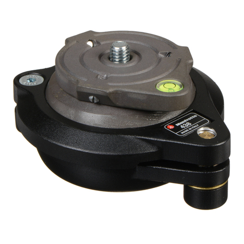
El adaptador de plato ha sido diseñado para permitir a cualquier modelo de rótula de
adaptarse al nuevo Plato de Liberación Rápida Manfrotto.
PREPARACIÓN
Monten la base “W” sobre la rótula utilizando el orificio roscado de 1/4” “A”.
SOLTAR EL PLATO DE LA CÁMARA DEL ADAPTADOR
Para quitar el plato “G” es necesario empujar completamente arriba la palanca de
seguridad “I” y al mismo tiempo deslizar el plato como muestra la fig. 2.
FIJAR EL PLATO A LA CÁMARA Y
El adaptador es suministrado con dos platos con diferentes aparatos antirotación: el
plato “G” con el pivote VHS para una utilización vídeo especifica, el plato “Y” con
bloqueo de deslizamiento para una utilización fotográfica o general.
FIJAR EL PLATO “G”
Si el camcorder no lleva el oreficio para recibir el pivote antirotación "P", desenroscen
y quiten el pivote “P” del plato "G".
Fijen el camcorder sobre el plato "G" enroscando el tornillo "M" en el oreficio roscado
de la cámara.
Por favor, quiden no apretar demasiado el tornillo porqué podrian dañar la base del
camcorder.
FIJAR EL PALTO “Y”
Muevan el bloqueo de deslizamiento”R” del plato “Y” de un lado como en la fig. 4.
Enroscen, no completamente, el tornillo de la cámara “X” en el orificio roscado de la
cámara y luego empujen el zócalo “Q” hacia el cuerpo de la cámara,después fijen la
cámara enroscando completamente el tornillo “X”.
Por favor, quiden no apretar demasiado el tornillo porqué podrian dañar la base del
camcorder.
NOTA
El bloqueo del deslizamiento “R” puede ser montado de cualquier lado del plato
adaptandose al modelo de la cámara.
Para cambiar la colocación, procedan como sigue:
- quiten el anillo grip “U” del plato con un destornillador asi el bloqueo del
deslizamiento “R” puede ser removido
- el bloqueo del deslizamiento “R” puede ser montado de cualquier lado del plato
adaptandose al modelo de la cámara.
ACOPLAR LA CÁMARA AL ADAPTADOR Y
Presionen el plato “G” o “Y” hacia abajo (fig. 6) e introduzcanlo en los lados dove tail
“T” hasta que la palanca de bloqueo “I” haga click bloqueando el plato.
Asegurense que el plato “G” o “Y” (fig. 7) esté completamente bloqueado
empujando abajo la palanca “I” y chequeando que la cámara se encuentre
bloqueada
SUELTEN LA CÁMARA
Siempre que haya que quitar la cámara de la rótula, sujete con seguridad la
cámara con una mano mientras manejan la palanca “I” con la otra mano.
INTRODUZIONE
L’adattatore consente di convertire qualunque testa per accettare il modello più
recente di Piastra Rapida Manfrotto.
PREPARAZIONE
Montare la base “W” sulla testa tramite l’attacco filettato “A” da 1/4”.
COME ESTRARRE LA PIASTRA DELLA FOTOCAMERA DALL’ADATTATORE Per
Rimuovere la piastra “G” è necessario premere verso l’alto e a fondo la leva di
sicurezza “I” e contemporaneamente fare scorrere la piastra come mostrato in figura 2.
COME FISSARE LA PIASTRA ALLA FOTOCAMERA E
L’adattatore viene fornito con due piastre dotate di differenti dispositivi antirotazione:
la piastra “G” dotata di piolino di tipo VHS per uso specifico con videocamere e la
piastra “Y” con fermo scorrevole per uso fotografico o generale.
MONTAGGIO DELLA PIASTRA “G”
Se la videocamera non dispone del foro per il piolino antirotazione "P", svitare e
rimuovere il piolino "P" dalla piastra "G".
Fissare la piastra “G” alla videocamera avvitando la vite "M" nell’apposito foro
filettato.
Per evitare di danneggiare la base della videocamera, fare attenzione a non stringere
troppo la vite.
MONTAGGIO DELLA PIASTRA “Y”
Muovere il fermo scorrevole “R” della piastra “Y” verso un lato come illustrato in
figura 4.
Avvitare parzialmente la vite “X” nel foro filettato della fotocamera e poi premere il
bordo “Q” contro il corpo della fotocamera, finendo poi di avvitare la vite "X".
Per evitare di danneggiare la base dell’apparecchio, fare attenzione a non stringere
troppo la vite.
NOTA
Il fermo scorrevole “R” può trovarsi su ogni lato della piastra, per adattarsi al meglio
alla forma della fotocamera.
Per cambiare la sua posizione, procedere come segue:
- con un cacciavite, rimuovere l’anello di ritenuta “U” dalla piastra, in modo da
potere rimuovere il fermo scorrevole “R”
- il fermo scorrevole “R” può essere rivolto verso qualsiasi lato della piastra, per
adattarsi alla forma della fotocamera
MONTAGGIO DELLA FOTOCAMERA SULL’ADATTATORE E
Premere la piastra “G” oppure “Y” verso il basso (fig. 6) ed inserirla nell’innesto a
coda di rondine “T” finché la leva di blocco “I” scatta, bloccando la piastra in
posizione.
Accertarsi che la piastra “G” oppure “Y” (fig. 7) sia bloccata completamente
premendo verso il basso la leva “I” e controllando che la fotocamera sia ben
ferma.
SMONTAGGIO DELLA FOTOCAMERA
Quando occorre rimuovere la fotocamera dalla testa, reggere saldamente la
fotocamera con una mano mentre si aziona la leva “I” con l’altra.
Cod. 384,66 - 09/04 Copyright © 2004 Manfrotto Bassano Italy
INSTRUCTIONS
384
1
2
3
3
4 5
4
5
6 7
8
1
2
3
3
4 5
4
5
6 7
8
GB FD
INTRODUCTION
L'adaptateur de plateau 384 a été conçu pour permettre le montage du dernier
plateau rapide de la gamme Manfrotto sur tous les modèles de rotules.
INSTALLATION
Montez la base "W" sur la rotule en vissant la vis 1/4" dans le filetage "A".
RETRAIT DU PLATEAU DE L'ADAPTATEUR
Pour retirer le plateau "G", levez entièrement le levier de sécurité "I" et faites coulisser
le plateau vers l'extérieur (voir figure 2).
FIXATION DU PLATEAU A L'APPAREIL PHOTO ET
L’adaptateur est fourni avec deux plateaux dotés de systèmes anti-rotation différents:
le plateau "G" comprend un ergot VHS permettant le montage d'un caméscope,
tandis que le plateau "Y" est équipé d'une plaque coulissante avec butée pour le
montage d'appareils photo ou pour une utilisation générale.
FIXATION DU PLATEAU "G"
Si le caméscope n'est pas doté d'un orifice dans lequel l'ergot "P" pourrait s'insérer,
dévissez complètement et retirez l'ergot "P" du plateau "G". Fixez le caméscope au
plateau "G" en vissant la vis de fixation "M" dans l'orifice fileté du caméscope. Faites
attention de ne pas trop serrer la vis au risque d'endommager la base du caméscope.
FIXATION DU PLATEAU "Y"
Faites coulisser la plaque "R" du plateau "Y" vers un côté, tel qu'illustré à la figure 4.
Vissez partiellement la vis "X" dans l'orifice fileté de l'appareil, ramenez la butée "Q"
contre le boîtier puis fixez ce dernier en vissant entièrement la vis "X".
Faites attention de ne pas trop serrer la vis au risque d'endommager la base de
l'appareil.
REMARQUE
La plaque coulissante "R" peut être montée de n'importe quel côté du plateau en
fonction de la forme du boîtier. Pour en modifier la position, procédez de la manière
suivante:
- retirez l'anneau de fixation "U" du plateau à l'aide d'un tournevis afin de pouvoir
retirer la plaque coulissante "R".
- montez la plaque coulissante "R" du côté du plateau qui convient le mieux à la
forme du boîtier.
MONTAGE D'UN APPAREIL SUR L'ADAPTATEUR DE PLATEAU ET
Insérez le plateau "G" ou "Y" sur lequel est fixé votre appareil dans les queues
d'aronde "T" (fig. 6) et appuyez sur l'ensemble jusqu'à entendre le "clic" produit par
le levier "I" indiquant que le plateau est fixé.
Assurez-vous que le plateau "G" ou "Y" (fig. 7) est bien verrouillé en appuyant
sur le levier "I" et vérifiez que l'appareil est correctement monté.
RETRAIT DE L'APPAREIL
Lorsque vous devez retirer l'appareil de la rotule, tenez-le fermement d'une
main tout en actionnant le levier "I" de l'autre.
INTRODUCTION
Adapter plate designed to convert any model head to take the latest Manfrotto Quick
Release plate.
SET-UP
Mount the base “W” onto the head using the 1/4” threaded hole “A”.
RELEASING THE CAMERA MOUNTING PLATE FROM THE ADAPTER
To remove plate “G” it is necessary to push up safety lever “I” fully and, in the same
time, to slide the plate as shown in figure 2.
ATTACHING PLATE TO CAMERA &
The adapter is supplied with two plates, with different anti-rotation devices: the plate
“G” with VHS pin for specific video use, the plate “Y” with sliding stop for
photographic or general use.
ATTACHING PLATE “G”
If the camcorder does not have a hole to accommodate the anti-rotation pin "P",
unscrew and remove pin "P" from plate "G".
Fix the camcorder onto plate "G" by screwing camera screw "M" into the camera's
threaded hole.
Please take care not to tighten too much the screw because you could damage
camcorder base.
ATTACHING PLATE “Y”
Move the sliding stop “R” of the plate “Y” at one side as shown in figure 4.
Screw, not completely, the camera screw “X” into the camera's threaded hole then
push the edge “Q” against camera body, then fix the camera by screwing completely
camera screw "X".
Please take care not to tighten too much the screw because you could damage
camcorder base.
NOTE
The sliding stop “R” can be mounted on every side of the plate, so it can be adapt to
the the shape of the camera.
For changing the position, proceed as follow:
- remove grip ring “U” from the plate with a screwdriver, so the sliding stop “R” can
be remove
- the sliding stop “R” can be mounted on every side of the plate in way to adapt it to
the shape of the camera
MOUNTING THE CAMERA ON TO ADAPTER &
Press the camera plate “G” or “Y” downwards (fig. 6) and insert it into the dovetail
sides “T” until locking lever “I” clicks and locks the plate.
Make sure that plate “G” or “Y” (fig. 7) is fully locked by pushing down lever “I”
and checking that the camera is fitted securely
RELEASING THE CAMERA
Whenever the camera needs to be removed from the head, hold the camera
securely in one hand while operating lever “I” with the other.
EINLEITUNG
Adapterplatte zur Anpassung beliebiger Stativköpfe an die neueste
Schnellwechselplatte von Manfrotto.
ANBRINGUNG
Bringen Sie den Sockel "W" über die 1/4"-Buchse "A" auf dem Stativkopf an.
ABNEHMEN DER KAMERAPLATTE VOM ADAPTER
Zum Abnehmen der Platte "G" muss diese bei ganz nach oben gedrücktem
Sicherungshebel "I" gemäß Abb. 2 geschoben werden.
ANSETZEN DER PLATTE AN DIE KAMERA UND
Der Adapter wird mit zwei Platten mit unterschiedlicher Drehsicherung geliefert: der
Platte "G" mit VHS-Stift speziell für Videokameras und der Platte "Y" mit Anschlag
für Fotokameras oder allgemeine Zwecke.
ANSETZEN DER PLATTE "G"
Wenn der Camcorder nicht über ein Loch zur Aufnahme des Stiftes "P" verfügt,
schrauben Sie diesen ab und entfernen ihn aus der Platte "G".
Befestigen Sie den Camcorder auf Platte "G", indem Sie die Kameraschraube "M" in
die Stativbuchse der Kamera schrauben.
Vermeiden Sie übermäßiges Anziehen der Schraube, das zur Beschädigung des
Camcorders führen könnte.
ANSETZEN DER PLATTE "Y"
Ziehen Sie den Anschlag "R" von Platte "Y" gemäß Abb. 4 aus.
Schrauben Sie die Kameraschraube "X" teilweise in die Stativbuchse der Kamera,
schieben Sie dann die Kante "Q" gegen das Kameragehäuse und ziehen Sie die
Kameraschraube "X" an. Vermeiden Sie übermäßiges Anziehen der Schraube, das
zur Beschädigung der Kamera führen könnte.
ANMERKUNG
Der ausziehbare Anschlag "R" kann an jede Seite der Platte angesetzt werden, so
dass er sich der Form der Kamera anpasst.
Zum Umsetzen des Anschlags verfahren Sie wie folgt:
- Entfernen Sie den Sprengring "U" mit Hilfe eines Schraubendrehens, so dass der
ausziehbare Anschlag "R" abgenommen werden kann.
- Der ausziehbare Anschlag "R" kann zur Anpassung an die Form der Kamera an
jede beliebige Seite der Platte angesetzt werden.
ANBRINGUNG DER KAMERA AM ADAPTER UND
Drücken Sie die Kameraplatte "G" bzw. "Y" in die Schwalbenschwanzführung "T"
(Abb. 6), bis der Hebel "I" die Platte verriegelt.
Vergewissern Sie sich, dass die Platte "G" bzw. "Y" (Abb. 7) fest sitzt, indem
Sie den Hebel "I" nach unten drücken und den Sitz der Kamera prüfen.
ABNEHMEN DER KAMERA
Zum Abnehmen der Kamera vom Stativkopf nehmen Sie diese fest in eine
Hand und drücken mit der anderen den Hebel "I".
1
2
3
3
4 5
4
5
6 7
8
1
2
3
3
4 5
4
5
6 7
8
1
2
3
3
4 5
4
5
6 7
8
G
I
A
W
2
1
2
1
U
R
I
I
G/Y
T
I
G/Y
I
U
R
1
2
Y
PGM
Y
R
R
Q
Q
XX
3
1
2
4
1
2
3
5 6
7
8
4
Other Manfrotto Camera Accessories manuals

Manfrotto C350N User manual

Manfrotto

Manfrotto C350N User manual

Manfrotto MKBFRTA4BK-BH User manual

Manfrotto

Manfrotto MKBFRTA4BK-BH User manual

Manfrotto MVG300XM User manual

Manfrotto

Manfrotto MVG300XM User manual

Manfrotto 494 User manual

Manfrotto

Manfrotto 494 User manual

Manfrotto 560B User manual

Manfrotto

Manfrotto 560B User manual

Manfrotto MVT535AQ User manual

Manfrotto

Manfrotto MVT535AQ User manual

Manfrotto 351MVB2 User manual

Manfrotto

Manfrotto 351MVB2 User manual

Manfrotto 331 User manual

Manfrotto

Manfrotto 331 User manual

Manfrotto MVM450A User manual

Manfrotto

Manfrotto MVM450A User manual

Manfrotto 055MFV User manual

Manfrotto

Manfrotto 055MFV User manual

Manfrotto 562B User manual

Manfrotto

Manfrotto 562B User manual

Manfrotto 056 User manual

Manfrotto

Manfrotto 056 User manual

Manfrotto 553 User manual

Manfrotto

Manfrotto 553 User manual

Manfrotto MT290DUA3 User manual

Manfrotto

Manfrotto MT290DUA3 User manual

Manfrotto 7302YB User manual

Manfrotto

Manfrotto 7302YB User manual

Manfrotto HiLite LL LB8803 User manual

Manfrotto

Manfrotto HiLite LL LB8803 User manual

Manfrotto 528X User manual

Manfrotto

Manfrotto 528X User manual

Manfrotto 745XB User manual

Manfrotto

Manfrotto 745XB User manual

Manfrotto 554 User manual

Manfrotto

Manfrotto 554 User manual

Manfrotto 678 User manual

Manfrotto

Manfrotto 678 User manual

Manfrotto Lumimuse User manual

Manfrotto

Manfrotto Lumimuse User manual

Manfrotto MBOOMCFVR-S User manual

Manfrotto

Manfrotto MBOOMCFVR-S User manual

Manfrotto 504 User manual

Manfrotto

Manfrotto 504 User manual

Manfrotto MVHN12AH User manual

Manfrotto

Manfrotto MVHN12AH User manual

Popular Camera Accessories manuals by other brands

Duracell Lithium/Manganese Dioxide Battery DL1/3N Specification sheet

Duracell

Duracell Lithium/Manganese Dioxide Battery DL1/3N Specification sheet

Videotec VERSO Hi-PoE IPM instruction manual

Videotec

Videotec VERSO Hi-PoE IPM instruction manual

Ameristep RAPTOR TRIPOD 7700 Instruction and safety manual

Ameristep

Ameristep RAPTOR TRIPOD 7700 Instruction and safety manual

TecnoVideo 129AC installation manual

TecnoVideo

TecnoVideo 129AC installation manual

Westcott 1874 Setup instructions

Westcott

Westcott 1874 Setup instructions

Aigis Mechtronics HS9386SS Installation and operating instructions

Aigis Mechtronics

Aigis Mechtronics HS9386SS Installation and operating instructions

Swann S275-7DE Specifications

Swann

Swann S275-7DE Specifications

Samsung SHG-222 Specification sheet

Samsung

Samsung SHG-222 Specification sheet

Turbo Energy Lithium Series instruction manual

Turbo Energy

Turbo Energy Lithium Series instruction manual

Sony VCT-D480RM Service manual

Sony

Sony VCT-D480RM Service manual

PROAIM JB-FR6T-00 Assembly manual

PROAIM

PROAIM JB-FR6T-00 Assembly manual

Feiyu FY WG manual

Feiyu

Feiyu FY WG manual

Cartoni PRO + User Manual/Maintenance

Cartoni

Cartoni PRO + User Manual/Maintenance

Westcott 1865 Setup instructions

Westcott

Westcott 1865 Setup instructions

Broncolor Minipuls C200 operating instructions

Broncolor

Broncolor Minipuls C200 operating instructions

Recsea WHC-G1XMKII manual

Recsea

Recsea WHC-G1XMKII manual

Ikan RECOIL-UGK quick start guide

Ikan

Ikan RECOIL-UGK quick start guide

Panasonic HX025 operating instructions

Panasonic

Panasonic HX025 operating instructions

manuals.online logo
manuals.online logoBrands
  • About & Mission
  • Contact us
  • Privacy Policy
  • Terms and Conditions

Copyright 2025 Manuals.Online. All Rights Reserved.