manuals.online logo
Brands
  1. Home
  2. •
  3. Brands
  4. •
  5. Manfrotto
  6. •
  7. Camera Accessories
  8. •
  9. Manfrotto 718B User manual

Manfrotto 718B User manual

Cod. 718,09 - 03/06 Copyright © 2004 Manfrotto Bassano Italy
ED
EINLEITUNG
Leichtes Stativ für Digitalkameras.
HAUPTMERKMALE
• Dreiwegekopf
• Bein-Schnellklemmung
• Einschließlich Tasche
AUFSTELLUNG
Öffnen Sie die drei Stativbeine.
Zur Höheneinstellung des Stativs sind die drei Stativbeine nach Lösen der
Klemme “A” am Klemmring “B” ausziehbar.
HÖHENEINSTELLUNG DER MITTELSÄULE
Zum Lösen der Mittelsäule “D” lösen Sie Klemme “E”.
Danach kann die Höhe der Säule wie gewünscht eingestellt werden.
Klemmen Sie die Säule mit “E”.
ANWEISUNGEN ZUM KAMERA- BZW. VIDEOKOPF
SCHNELLWECHSELPLATE VOM KOPF ENTFERNEN
Zum Abnehmen der Platte “G” muss die Sicherung “I” voll gedrückt und die
Platte gleichzeitig gemäß Abb. 3 verschoben werden.
ABRINGUNG EINES CAMCORDERS AUF DER PLATTE
Wenn der Camcorder nicht über ein Loch zur Aufnahme der
Verdrehungssicherung “P” (Abb. 4) verfügt, muss der Stift “P” (Abb. 4) von
unten herausgeschoben werden. Bewahren Sie ihn für eventuelle spätere
Verwendung an einem sicheren Ort auf.
Sichern Sie den Camcorder auf Platte “G”, indem Sie die Kameraschraube
“M” in das Stativgewinde der Kamera schrauben, OHNE GEWALT
ANZUWENDEN.
Vor der endgültigen Klemmung sollten Sie das Camcorder-Objektiv auf den
Stift “P” bzw. die Markierung “LENS” auf der Kameraplatte “G” ausrichten.
ANBRINGUNG DER KAMERA AUF DEM STATIVKOPF
Schieben Sie die Kameraplatte “G” (Abb. 5) unter Druck in die
Schwalbenschwanzführung “T”, bis der Klemmhebel “I” einrastet und die
Platte fixiert.
ACHTUNG
Bitte vergewissern Sie sich, dass die Platte “G” (Abb. 6) sicher
verriegelt ist, und prüfen Sie, dass die Kamera fest auf dem Kopf sitzt.
ENTRIEGELUNG DER KAMERA
Wenn die Kamera vom Stativkopf abgenommen werden muss, nehmen Sie
sie fest in eine Hand und betätigen mit der anderen den Hebel “I”.
EINSATZ DES STATIVKOPFES UND
Der Stativkopf gestattet Horizontalschwenks um 360° sowie Vertikalschwenks
(+150° / -80°) mit Hilfe des Schwenkhebels “F” (Abb. 1).
Beide Schwenkbewegungen können mit dem Hebel “F” geklemmt werden:
Lösen Sie den Hebel durch Linksdrehung zur Einstellung, und klemmen Sie
ihn durch Rechtsdrehung.
Mit Hilfe einer 90°-Drehung sind auch Hochaufnahmen möglich.
Lösen Sie Klemme “C” (Abb. 8) für den Schwenk.
INTRODUCCIÓN
De peso ligero, ideal para cámars digitales.
CARACTERISTICAS
• Columna central reversible
• Bloqueos rápidos de palanca para las patas
• Bolsa incluida
PREPARACIÓN
Abran las 3 patas del trípode.
Para ajustar la altura del trípode cada pata dispone de un expansor
telescópico que puede ser soltado por medio de una palanca de giro “A” en
la embrazadera de bloqueo “B”.
AJUSTE DE LA ALTURA DE LA COLUMNA CENTRAL
Para soltar la columna central “D”, desbloquéen el mando “E” y ajusten la
altura de la columna según su necesidad.
Aprieten el mando “E” para bloquear la posición.
INSTRUCCIÓNES RÓTULA
QUITAR EL PLATO RÁPIDO DE LA RÓTULA
Para quitar el plato “G” es necesario empujar completamente abajo la
palanca de seguridad “I” y simultáneamnete para deslizar el plato como
muestra la fig. 3.
ACOPLAR LA CAMCORDER AL PLATO
Si su cámara no tiene un agujero para un pin VHS, necesitará quitar el pin
“P” (fig. 4) presionándolo hacia fuera desde debajo. Mantenga el pin VHS en
un lugar seguro por si lo necesita en el futuro.
Fijen el camcorder al plato “G” (fig. 4) enroscando el tornillo “M” en el
oreficio roscado de la cámara sin emplear fuerza utilizando el anillo “Q” .
Antes del bloqueo total alinee la óptica del camcorder con la clavija “P” si
procede o con la marca “LENS” del plato “G”.
ACOPLAR LA CÁMARA A LA RÓTULA
Introduzcan el plato “G” (fig. 4) en los dove tail “T” sobre la rótula y luego
empujen el plato “G” hacia abajo hasta cuando la palanca de bloqueo “I”
haga click y bloquée el plato.
ADVERTENCIA
Asegurense que el plato “G” (fig. 6) esté completamente bloqueado y
chequeen que la cámara se ajuste perfectamente a la rótula.
QUITAR LA CÁMARA DE LA RÓTULA
Siempre que haya que quitar la cámara de la rótula, sujete con seguridad la
cámara con una mano mientras manejan la palanca “I” con la otra mano.
UTILIZACIÓN DE LA RÓTULA Y
La rótula dispone de un giro de 360° y de una inclinación de +150° / -80°
controladas por medio del manillar “F” (fig. 1).
El movimiento de giro y el movimiento de inclinación se pueden bloquear
utilizando el mango “F”: rodéen el mango en sentido antihorario para poder
colocar la rótula en la posición deseada y luego bloquéenla rodeandolo en
sentido hórario.
La rótula también incluye un movimiento nivelador (90°) que permite hacer
disparos en posición vertical.
Desenrosquen el mando “C” (fig. 8) para librar el movimiento.
1
2
3
4
5
6
8
81
1
2
3
4
5
8
6
1 8
INSTRUCTIONS
166.3 cm 1.4 kg 2.5 kg
65.5” 3.09 lbs 5.5 lbs
718B 718SHB
123.2 cm 1.2 kg 2.5 kg
48.5” 2.74 lbs 5.5 lbs
GB FI
INTRODUCTION
Trépied léger conçu pour les appareils photo numériques.
CARACTÉRISTIQUES PRINCIPALES
• Rotule 3D
• Leviers de blocage rapide des jambes
• Sac de transport inclus
INSTALLATION
Ouvrez les 3 jambes du trépied.
Pour régler la hauteur du trépied, vous pouvez déployer les sections
téléscopiques des jambes en ouvrant les leviers de blocage “A” situés sur les
bagues “B”.
RÉGLAGE DE LA HAUTEUR DE LA COLONNE CENTRALE
Pour libérer la colonne centrale “D”, débloquez le levier “E” et réglez la
hauteur de la colonne comme vous le souhaitez.
Rebloquez le levier “E” pour verrouiller la colonne à la hauteur choisie.
INSTRUCTIONS CONCERNANT LA ROTULE
RETRAIT DU PLATEAU RAPIDE DE LA ROTULE
Pour retirer le plateau coulissant rapide “G”, baissez entièrement le levier de
sécurité “I” et faites coulisser le plateau simultanément (voir figure 3).
FIXATION DE L’APPAREIL AU PLATEAU
Si votre caméscope n'est pas doté d'un tel orifice, il vous faudra retirer
également l'ergot “P” (fig. 4) en le poussant par en dessous. Conservez
l'ergot VHS pour pouvoir l'utiliser ultérieurement au besoin.
Fixez l'appareil photo au plateau “G” (fig. 4) en vissant la vis de fixation “M”
dans l'orifice fileté du boîtier SANS FORCER.
Avant de bloquer ce montage, alignez l'objectif avec l'ergot “P” si c'est
possible, ou avec l'inscription “LENS” du plateau “G” le cas échéant.
FIXATION DE L’APPAREIL A LA ROTULE
Insérez le plateau rapide “G”, sur lequel est fixé l'appareil photo, dans les
queues d'aronde “T” (fig. 5) et appuyez sur le boîtier jusqu'à entendre un
“clic” indiquant que le levier “I” a correctement verrouillé le plateau.
AVERTISSEMENT
Assurez-vous que le plateau rapide “G” (fig. 6) est correctement
verrouillé et que l'appareil est correctement fixé à la rotule.
RETRAIT DE L'APPAREIL
Lorsque vous devez retirer l'appareil de la rotule, tenez-le fermement d'une
main tout en actionnant le levier “I” de l'autre.
UTILISATION DE LA ROTULE ET
La poignée “F” permet de contrôler un mouvement panoramique de 360° et
une bascule avant/arrière de +150° à –80° de la rotule.
Les mouvements panoramiques et de bascule verticale peuvent être bloqués
à l'aide de la poignée “F”: tournez la poignée dans le sens inverse des
aiguilles d'une montre pour placer la rotule dans la position souhaitée et
bloquez-la en tournant la poignée dans le sens des aiguilles d'une montre.
La rotule permet également un mouvement latéral (à 90°) pour des prises de
vues verticales.
Pour obtenir ce déplacement latéral, desserrez le bouton “C” (fig. 8).
INTRODUZIONE
Treppiede leggero studiato per le fotocamere e le videocamere digitali.
CARATTERISTICHE PRINCIPALI
• Testa a tre movimenti
• Bloccaggio rapido degli allungamenti delle gambe
• Sacca da trasporto inclusa
PREPARAZIONE
Divaricare le 3 gambe.
Per regolare l’altezza del treppiede, ogni gamba dispone di allungamenti
telescopici che si possono liberare ruotando la leva “A” sul manicotto “B”.
REGOLAZIONE DELL’ALTEZZA DELLA COLONNA CENTRALE
Per liberare la colonna centrale “D”, sbloccare la leva “E” e regolare a
piacere l’altezza della colonna.
Per bloccare la colonna in posizione stringere la leva “E”.
ISTRUZIONI SULL’USO DELLA TESTA
RIMOZIONE DELLA PIASTRA RAPIDA DALLA TESTA
Per rimuovere la piastra “G” è necessario premere verso il basso e a fondo
la leva di sicurezza “I” facendo contemporaneamente scorrere la piastra
come mostrato in figura 3.
MONTAGGIO DELLA VIDEOCAMERA SULLA PIASTRA
Se la vostra videocamera non dispone di foro per il perno VHS, è possibile
rimuovere il perno “P” (fig. 4) premendolo da sotto per farlo uscire dalla sede.
Conservare al sicuro il perno VHS per un possibile utilizzo futuro.
Fissare la videocamera alla piastra “G” avvitando a fondo la vite “M” nel foro
filettato alla base della videocamera SENZA APPLICARE FORZA ECCESSIVA.
Prima di arrivare al bloccaggio finale, allineare l’obiettivo della videocamera
col piolino “P” se presente, o con la scritta “LENS” sulla piastra “G”.
MONTAGGIO DELLA VIDEOCAMERA SULLA TESTA
Premere la piastra rapida “G” verso il basso (fig. 5) ed inserirla negli innesti
a coda di rondine “T” fino a fare scattare la leva di blocco “I” che blocca la
piastra.
AVVERTENZA
Occorre verificare che la piastra “G” (fig. 6) sia completamente
bloccata e controllare che la videocamera sia fissata saldamente alla
testa.
RIMOZIONE DELLA VIDEOCAMERA DALLA TESTA
Ogni qualvolta occorra rimuovere la videocamera dalla testa, si deve
reggere saldamente la videocamera con una mano mentre si aziona la leva
di blocco “I” con l’altra mano.
USO DELLA TESTA E
La testa dispone di movimento panoramico di 360° e di inclinazione
verticale (+150°/-80°) che vengono controllati dalla leva di comando “F” (fig. 1).
Il movimento panoramico e l’inclinazione possono essere bloccati con
l’impugnatura “F”: ruotare l’impugnatura in senso antiorario per sbloccare il
movimento della testa, raggiungere la posizione desiderata e quindi
bloccare la testa in posizione ruotando l’impugnatura in senso orario.
La testa dispone anche di un movimento a 90° per consentire riprese con la
fotocamera in verticale.
Per sbloccare il movimento svitare la manopola “C” (fig. 8).
1
2
3
4
5
6
8
1
2
3
4
5
8
81
81
6
INTRODUCTION
Lightweight tripod designed for digital cameras.
KEY FEATURES
- 3 way head
- Rapid action lever leg extension locks
- Bag included
SET UP
Open the 3 tripod legs.
To adjust the height of the tripod, each leg has telescopic extensions that can
be released by rotating lever “A” on the locking collar “B”.
CENTER COLUMN HEIGHT ADJUSTMENT
To release the center column “D”, unlock knob “E” and adjust the height of the
column as required. Tighten knob “E” to lock the column in position.
HEAD INSTRUCTIONS
REMOVE QUICK RELEASE PLATE FROM HEAD
To remove plate “G” it is necessary to push down safety lever “I” fully and, in
the same time, to slide the plate as shown in figure 3.
ASSEMBLING CAMCORDER ON PLATE
If your camcorder doesn’t have a hole for a VHS pin, you will need to remove
pin “P” (fig. 4) by pushing it out from underneath. Keep the VHS pin in a safe
place in case you need it in the future.
Fix the camcorder onto plate “G” by screwing home camera screw “M” into
the camera's threaded hole WITHOUT APPLYING FORCE.
Before fully locking, align the camcorder lens with pin “P” if appropriate, or
with the “LENS” marking on the camera plate “G”.
MOUNTING THE CAMERA ON THE HEAD
Press the camera plate “G” downwards (fig. 5) and insert it into the dovetail
sides “T” until locking lever “I” clicks and locks the plate.
WARNING
Please ensure that plate “G” (fig. 6) is fully locked and checking that the
camera is fitted securely to the head.
RELEASING THE CAMERA
Whenever the camera needs to be removed from the head, hold the camera
securely in one hand while operating lever “I” with the other.
HEAD USE &
The head features 360° pan and vertical tilt (+150° / -80°) which are controlled
using the pan bar “F” (fig. 1).
The pan and vertical tilt movement can be locked using the handle “F”: rotate
the handle anti clockwise directions to allow the head to be moved to the
position required and then lock in position by rotating clockwise.
The head is also provided by a leveling movement (90°) that allows the vertical
photographic shot. Unscrew the knob “C” (fig. 8) to release the movement.
B
A
D
F
E
G
M
B
A
B
A
2
1
2
1
G
T
GI
I
C
1
2I
P
G
2
1
2
1
13
1
2
3
4
5
6
8
8
1
2
4
78
5 6
P
P
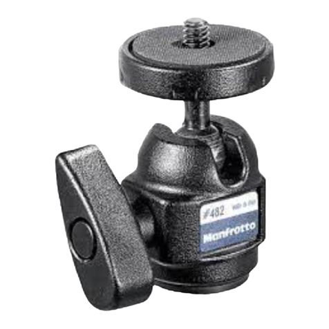
This manual suits for next models

1

Other Manfrotto Camera Accessories manuals

Manfrotto MKC3-H01 User manual

Manfrotto

Manfrotto MKC3-H01 User manual

Manfrotto MT290DUA3 User manual

Manfrotto

Manfrotto MT290DUA3 User manual

Manfrotto MT190X3 User manual

Manfrotto

Manfrotto MT190X3 User manual

Manfrotto 494 User manual

Manfrotto

Manfrotto 494 User manual

Manfrotto 804RC2 User manual

Manfrotto

Manfrotto 804RC2 User manual

Manfrotto 808RC4 User manual

Manfrotto

Manfrotto 808RC4 User manual

Manfrotto 454 User manual

Manfrotto

Manfrotto 454 User manual

Manfrotto MT190GOA4 User manual

Manfrotto

Manfrotto MT190GOA4 User manual

Manfrotto 484 User manual

Manfrotto

Manfrotto 484 User manual

Manfrotto 303 User manual

Manfrotto

Manfrotto 303 User manual

Manfrotto 438 User manual

Manfrotto

Manfrotto 438 User manual

Manfrotto 405 User manual

Manfrotto

Manfrotto 405 User manual

Manfrotto Lastolite Lumen8 User instructions

Manfrotto

Manfrotto Lastolite Lumen8 User instructions

Manfrotto PRO LIGHT 3N1-36 User manual

Manfrotto

Manfrotto PRO LIGHT 3N1-36 User manual

Manfrotto 627 User manual

Manfrotto

Manfrotto 627 User manual

Manfrotto MVH500A User manual

Manfrotto

Manfrotto MVH500A User manual

Manfrotto Lastolite Ezybalance User manual

Manfrotto

Manfrotto Lastolite Ezybalance User manual

Manfrotto MS0490C User manual

Manfrotto

Manfrotto MS0490C User manual

Manfrotto MVH502A User manual

Manfrotto

Manfrotto MVH502A User manual

Manfrotto 595B User manual

Manfrotto

Manfrotto 595B User manual

Manfrotto 503HDV User manual

Manfrotto

Manfrotto 503HDV User manual

Manfrotto 501HDV User manual

Manfrotto

Manfrotto 501HDV User manual

Manfrotto 488RC0 User manual

Manfrotto

Manfrotto 488RC0 User manual

Manfrotto C350N User manual

Manfrotto

Manfrotto C350N User manual

Popular Camera Accessories manuals by other brands

Broncolor Minipuls C200 operating instructions

Broncolor

Broncolor Minipuls C200 operating instructions

Avigilon ES-HD-HWS instruction manual

Avigilon

Avigilon ES-HD-HWS instruction manual

Athlon AL28 User manual / care instructions

Athlon

Athlon AL28 User manual / care instructions

Panasonic WV-LXY18C4 quick start guide

Panasonic

Panasonic WV-LXY18C4 quick start guide

CHIEF FVS200 installation instructions

CHIEF

CHIEF FVS200 installation instructions

Panasonic H-H014A operating instructions

Panasonic

Panasonic H-H014A operating instructions

Oben CTM-2400 manual

Oben

Oben CTM-2400 manual

PhaseOne XF V-Grip quick guide

PhaseOne

PhaseOne XF V-Grip quick guide

Kummert K-70 instruction manual

Kummert

Kummert K-70 instruction manual

Nikon AstroIR manual

Nikon

Nikon AstroIR manual

Canon RS-60E3 instructions

Canon

Canon RS-60E3 instructions

Sony SMAD-P5 operating instructions

Sony

Sony SMAD-P5 operating instructions

Inventus Power PROTRXion M-24V80-TRX user guide

Inventus Power

Inventus Power PROTRXion M-24V80-TRX user guide

Polaroid PL-LCDWRNK user guide

Polaroid

Polaroid PL-LCDWRNK user guide

Abt Powerline SC Series Product guide

Abt

Abt Powerline SC Series Product guide

Zircon StudSensor Pro user manual

Zircon

Zircon StudSensor Pro user manual

LENCO DC-5105 WATERPROOF - CAMERA CASE manual

LENCO

LENCO DC-5105 WATERPROOF - CAMERA CASE manual

Pentax Stereo Adapter Set operating manual

Pentax

Pentax Stereo Adapter Set operating manual

manuals.online logo
manuals.online logoBrands
  • About & Mission
  • Contact us
  • Privacy Policy
  • Terms and Conditions

Copyright 2025 Manuals.Online. All Rights Reserved.