manuals.online logo
Brands
  1. Home
  2. •
  3. Brands
  4. •
  5. Manfrotto
  6. •
  7. Camera Accessories
  8. •
  9. Manfrotto 488RC0 User manual

Manfrotto 488RC0 User manual

E
I
INTRODUCCIÓN
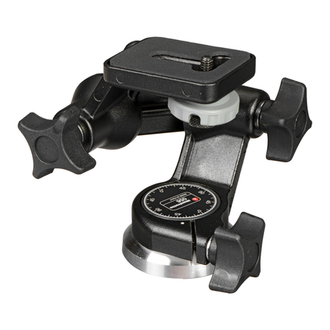
Una rótula de bola profesional diseñada para cámaras de tamaño medio.
PREPARACIÓN
Acoplen la rótula al trípode utilizando una rosca hembra 3/8” “A”.
La plataforma superior de los trípodes Manfrotto viene equipada con tres tornillos
hundidos “B” que presionan contra la base de la rótula para asegurar un eficaz y
seguro bloqueo.
RETIRAR EL PLATO RÁPIDO DE LA RÓTULA
Para remover el plato “G” es necesario rodear completamente la palanca de seguridad “I”
siguiendo la dirección de la flecha junto a la palanca “H” hasta que la clavija “L” haga click
abriendose y soltando el plato.
(para que la palanca “H” funcione completamente, el segundo seguro “I” debe funcionar
simultáneamente como indicado).
ACOPLAR LA CÁMARA AL PLATO
Fijen la camara al plato “G" enroscando el tornillo "M” en el orificio roscado de la cámara
SIN EMPLEAR FUERZA (antes recuerden desenroscar completamente el anillo de bloqueo
“Q”).
Antes de bloquearla completamente, alinee el eje panorámico con uno de los vértices “R”
del plato hexagonal “G” de la cámara.
Aseguren completamente la cámara enroscando el anillo “Q” al plato “G” (ej. con
destornillador).
El anillo de bloqueo “Q” incluye una ranura “S” para facilitar el cierre.
ACOPLAR LA CÁMARA A LA RÓTULA Y
Introduzcan el plato “G” (fig. 4) en los dove tail “T” sobre la rótula y luego empujen el
plato “G” hacia abajo hasta cuando la palanca de bloqueo “H” haga click y se cierre.
Asegurense que el plato “G” (fig. 5) esté completamente bloqueado empujando la
palanca “H” completamente atrás hacia el nivel de burbuja y chequéen que la cámara
se ajuste perfectamente
QUITAR LA CÁMARA DE LA RÓTULA
Siempre que haya que quitar la cámara de la rótula, sujeten con seguridad la cámara
con una mano mientras manejan la palanca de bloqueo “H” y con la otra mano la
palanca de seguridad “I”.
UTILIZACIÓN
La rótula trabaja con movimientos de bola y panoramicos autónomos.
El eje panorámico puede bloquearse utilizando la palanca “E”.
Para librar el movimiento, suelten la palanca “E” rodeando en sentido antihorario
Una vez obtenida la posición deseada, bloqueen la rótula girando la palanca “E”
completamente en sentido hórario.
El mando “C” bloquea el movimiento de la rótula.
Para utilizar con seguridad la rótula de bola, mientras sueltan la bola sujeten siempre
la cámara con una mano.
Para librar la bola “D” y colocar la cámara, suelten el mando “C” rodeando en sentido
antihorario.
Una vez obtenida la posición deseada, bloquéen la bola “D” girando completamente el
mando “C” en sentido hórario.
La rótula incluye 2 niveles de burbuja "J" (fig. 1) útiles para nivelar la rótula.
Nota: el ángulo de la palanca “E” puede ser recolocado como requerido sin afectar el
mismo bloqueo. Empujen la palanca hacia el externo, rodeen como requerido y suelten y se
colocará en la nueva posición.
La manutención de las rótulas es libre.
No lubrificar con aceite o silicón.
INTRODUZIONE
Testa a sfera professionale progettata per fotocamere di medio formato.
PREPARAZIONE
Montare la testa sul treppiede usando il foro filettato “A” da 3/8”.
I dischi di ancoraggio dei treppiedi Manfrotto sono dotati di tre grani “B” da stringere
contro la base della testa per garantirne un bloccaggio sicuro.
RIMOZIONE DELLA PIASTRA A SGANCIO RAPIDO DALLA TESTA
Per rimuovere la piastra “G” è necessario ruotare completamente il fermo di sicurezza “I”
nella direzione della freccia insieme alla leva “H” fino a quando il piolino “L” scatta e
sblocca la piastra. Per consentire il movimento completo della leva “H”, il fermo secondario
di sicurezza “I” va azionato simultaneamente come indicato.
MONTAGGIO DELLA FOTOCAMERA SULLA PIASTRA
Fissare la fotocamera sulla piastra "G" avvitando a fondo la vite "M" nel foto filettato della
fotocamera SENZA STRINGERE SUBITO LA VITE DEL TUTTO (ricordarsi di svitare prima
del tutto la ghiera di blocco “Q”). Prima di bloccare completamente la fotocamera sulla
piastra “G”, allineare l’obiettivo con uno dei vertici “R” della piastra esagonale “G”.
Fissare bene la fotocamera avvitando la ghiera di blocco “Q” contro la piastra “G”
(ad esempio con un cacciavite). La ghiera di blocco “Q” è dotata di una tacca “S” per
facilitarne il serraggio.
MONTAGGIO DELLA FOTOCAMERA SULLA TESTA E
Inserire la piastra con la fotocamera “G” (fig. 4) negli innesti a coda di rondine “T”
sulla testa e premere la piastra “G” finché la leva di blocco “H” scatta in posizione
chiusa.
Accertarsi che la piastra “G” (fig. 5) sia completamente bloccata premendo a fondo
la leva “H” verso la livella a bolla e controllando che la fotocamera sia fissata
saldamente sulla testa.
RIMOZIONE DELLA FOTOCAMERA DALLA TESTA
Quando occorre rimuovere la fotocamera dalla testa, reggere saldamente la
fotocamera con una mano mentre si sblocca la leva di blocco "H" e il fermo di
sicurezza “I” con l’altra.
USO
La testa dispone di movimento panoramico e movimenti a sfera indipendenti.
La leva “E” blocca il movimento panoramico.
Per sbloccare il movimento, allentare la leva “E” ruotandola in senso antiorario.
Raggiunta la posizione desiderata, bloccare la testa ruotando a fondo la leva “E” in senso
orario.
La manopola “C” blocca il movimento della sfera.
Per un uso sicuro della testa a sfera, reggere sempre la fotocamera con una mano
quando si sblocca la sfera.
Per sbloccare la sfera “D” per posizionare la fotocamera, sbloccare la manopola “C”
ruotandola in senso antiorario.
Raggiunta la posizione voluta, bloccare la sfera “D” ruotando a fondo la manopola “C” in
senso orario.
Nota
La posizione della leva “E” può essere variata in qualsiasi momento per maggior comodità
di presa e utilizzo, senza influire sul blocco stesso. Tirare la leva verso l’esterno, effettuare
la rotazione voluta e rilasciare la leva, che rientrerà automaticamente in sede nella nuova
posizione.
La testa non richiede manutenzione. Non lubrificatela con alcun tipo di olio o
lubrificante.
Cod. 488,36 - 09/04 Copyright © 2004 Manfrotto Bassano Italy 13.4 cm 0.83 kg 8 kg
5 1/4” 1.82 lbs 17.6 lbs
INSTRUCTIONS
488RC0
1
2
3
45
6
1
1
2
3
45
6
1
J
D
J
E
C
B
A
1
1
2
H
H
L
G
G
I
LENS
R
M
Q
G
S
L
H
IG
2
T
G
2
1
11
GB FD
INTRODUCTION
Rotule ball professionnelle pour les appareils photo moyen format.
INSTALLATION
Fixez la rotule au trépied en insérant la vis 3/8" du trépied dans le filetage "A" de la rotule.
Le socle de la colonne centrale des trépieds Manfrotto est équipé de trois vis "B" qui,
vissées à la base de la rotule, permettent un verrouillage encore plus sûr et efficace.
RETRAIT DU PLATEAU RAPIDE DE LA ROTULE
Pour retirer le plateau rapide "G", il faut d'abord tourner complètement le levier de sécurité
"I" dans le sens indiqué par la flèche, puis ouvrir le levier "H" jusqu'à ce qu'un "clic" indique
que le cliquet "L" a libéré le plateau. (Pour pouvoir ouvrir entièrement le levier "H", il est
nécessaire de tourner le levier de sécurité secondaire "I" simultanément, de la manière
illustrée.)
FIXATION DU PLATEAU A L'APPAREIL
Fixez le plateau rapide "G" (fig. 3) à l'appareil photo en vissant la vis de fixation "M" dans
l'orifice fileté de l'appareil, SANS FORCER (pensez à desserrer entièrement la bague "Q" en
premier lieu).
Avant de verrouiller ce montage, alignez l'objectif de l'appareil avec l'un des axes "R" du
plateau hexagonal "G".
Vissez la bague de serrage "Q" contre le plateau "G" pour verrouiller le montage (à
l'aide d'un tournevis, par exemple).
La bague de serrage "Q" comporte une fente "S" facilitant le serrage.
FIXATION DE L'APPAREIL A LA ROTULE ET
Insérez le plateau rapide "G" (fig. 4) dans les queues d'aronde "T" de la base
supérieure de la rotule puis rabattez le plateau "G" sur la rotule jusqu'à entendre un
"clic" indiquant que le levier de blocage "H" a verrouillé le plateau.
Assurez-vous que le plateau rapide "G" (fig. 5) est correctement fixé en poussant
complètement le levier "H" et vérifiez que l'appareil est solidement fixé à la rotule.
RETRAIT DE L'APPAREIL DE LA ROTULE
Lorsque vous devez retirer votre appareil de la rotule, tenez-le fermement d'une main
tandis que vous actionnez le levier "H" et le levier de sécurité "I" de l'autre.
UTILISATION
Les mouvements panoramiques et de bascule de la rotule sont indépendants.
Le levier "E" permet de bloquer les mouvements panoramiques.
Pour libérer le mouvement panoramique, desserrez le levier "E" en le tournant dans le sens
inverse des aiguilles d'une montre.
Une fois la position souhaitée obtenue, bloquez de nouveau la rotule en serrant
complètement le levier "E" dans le sens des aiguilles d'une montre.
La molette "C" permet de bloquer les mouvements de bascule.
Pour utiliser la rotule ball de manière sûre, tenez toujours votre appareil photo d'une
main lorsque vous débloquez la boule.
Pour débloquer la rotule ball "D" et pouvoir ainsi changer la position de votre appareil,
desserrez la molette "C" en la tournant dans le sens inverse des aiguilles d'une montre.
Une fois la position souhaitée obtenue, bloquez de nouveau la rotule ball "D" en serrant la
molette "C" dans le sens des aiguilles d'une montre.
La rotule est équipée de 2 niveaux à bulle "J" (fig. 1) permettant de la mettre facilement à
niveau.
Remarque :
Le levier "E" est indexé de façon à pouvoir être positionné différemment sans que cela ait
d'incidence sur le système de blocage. Tirez le levier vers vous, tournez-le dans le sens
souhaité puis relâchez-le et il se mettra automatiquement dans cette nouvelle position.
Les rotules ne nécessitent pas d'entretien. Ne les lubrifiez pas avec de l'huile ou de la
silicone.
INTRODUCTION
A professional ball head designed for medium-format cameras.
SET UP
Assemble the head on the tripod using 3/8” female thread “A”.
The top plate on Manfrotto tripods are equipped with three set screws “B” which
clamp against the base of the head to ensure effective and secure locking.
REMOVE QUICK RELEASE PLATE FROM HEAD
To remove plate “G” it is necessary to rotate safety lever “I” fully in the direction of the arrow
together with lever “H” until peg “L” clicks open and releases the plate.
(To operate lever “H” full, the secondary safety latch “I” must be operated simultaneously as
indicated.)
ATTACHING PLATE TO CAMERA
Fix the camera plate “G” by screwing home camera screw “M” into the camera’s threaded
hole WITHOUT APPLYING FORCE (remember to unscrew locking ring “Q” completely first).
Before fully locking, align the camera lens with one of the “R” vertexes of the hexagon
camera plate “G”.
Secure the camera fully by screwing locking ring “Q” against plate “G” (e.g. with
screwdriver).
Locking ring “Q” is equipped with slot “S” to facilitate tightening.
MOUNTING THE CAMERA ON THE HEAD &
Insert the camera plate “G” (fig. 4) into the dovetail sides “T” on top of the head and
then press plate “G” downwards until locking lever “H” clicks and closes.
Make sure that plate “G” (fig. 5) is fully locked by pushing lever “H” all the way back
towards the spirit level and checking that the camera is fitted securely to the head.
REMOVE THE CAMERA FROM THE HEAD
Whenever the camera needs to be removed from the head, hold the camera securely
in one hand while operating locking lever “H” and safety lever “I” with the other.
USE
The head has panoramic and ball independent movements.
The lever “E” locks the panoramic movement.
To release the movement, unlock lever “E” by rotating anticlockwise
Once the desired position is achieved, lock the head by turning lever “E” fully clockwise.
The knob “C” locks the ball movement.
To ensure that the ball head is used safety, always hold the camera with one hand
while releasing the ball.
To release the ball “D” for positioning the camera, unlock knob “C” by rotating anticlockwise
Once the desired position is achieved, lock the ball “D” by turning knob “C” fully clockwise.
The head is equipped with 2 spirit levels "J" (fig. 1) which are useful for leveling the head.
Note
The angle of the lever “E” can be repositioned as required without effecting the lock itself.
Pull the lever outwards, rotate as required and release and it will locate in the new position.
The heads are maintenance-free.
Do not lubricate with any oil or silicon.
EINLEITUNG
Professioneller Kugelkopf für Mittelformatkameras.
ANBRINGUNG
Bringen Sie den Kugelkopf über seine 3/8"-Gewindebuchse "A" auf dem Stativ an.
Die Kopfplatte von Manfrotto Stativen ist mit drei Stellschrauben "B" versehen, die
sichere Fixierung am Sockel des Kugelkopfes gewährleisten.
ABNEHMEN DER SCHNELLWECHSELPLATTE VOM KUGELKOPF
Zum Abnehmen der Platte "G" muss der Sicherungshebel "I" zusammen mit Hebel "H" bis
zum Anschlag in Pfeilrichtung gedreht werden, bis Bolzen "L" zurückschnappt und die
Platte freigibt. (Für einen vollen Schwenk von Hebel "H" muss die Sekundärsicherung "I"
wie angegeben gleichzeitig betätigt werden.)
ANSETZEN DER PLATTE AN DIE KAMERA
Befestigen Sie die Kameraplatte "G", indem Sie die Kameraschraube "M" OHNE
GEWALTANWENDUNG in die Stativbuchse der Kamera schrauben. (Hierzu muss zunächst
der Klemmring "Q" ganz abgeschraubt werden.)
Vor dem Anziehen der Schraube richten Sie die Aufnahmeachse auf eine Achse "R" der
sechseckigen Kameraplatte "G" aus.
Sichern Sie die Kamera durch Anziehen des Klemmrings "Q" an die Platte "G" (z.B.
mit einem Schraubendreher). Erleichtert wird dies durch den Schlitz "S" im
Klemmring "Q".
ANSETZEN DER KAMERA AN DEN KUGELKOPF UND
Setzen Sie die Kameraplatte "G" (Abb. 4) in die Schwalbenschwanzführung "T" auf
dem Kugelkopf ein und drücken Sie sie an, bis der Klemmhebel "H" einrastet und
verriegelt.
Vergewissern Sie sich, dass die Platte "G" (Abb. 5) sicher verriegelt ist, indem Sie
Hebel "H" bis zum Anschlag nach hinten in Richtung auf die Wasserwaage schieben
und die Kamera auf festen Sitz prüfen.
ABNEHMEN DER KAMERA VOM KUGELKOPF
Wenn die Kamera vom Kugelkopf abgenommen werden muss, halten Sie sie fest mit
einer Hand, während Sie mit der anderen Klemmhebel "H" und Sicherungshebel "I"
betätigen.
BEDIENUNG
Der Kopf hat getrennte Schwenk- und Kugelbewegungen.
Hebel "E" klemmt die Schwenkbewegung.
Zum Lösen der Bewegung drehen Sie Hebel "E" entgegen dem Uhrzeigersinn.
Sobald die gewünschte Stellung erreicht ist, klemmen Sie den Kopf, indem Sie Hebel "E"
an seinen rechten Anschlag bringen.
Knopf "C" klemmt die Kugelbewegung.
Aus Sicherheitsgründen sollten Sie die Kamera beim Lösen der Kugelklemmung
stets mit einer Hand festhalten.
Zum Lösen der Kugel "D" zur Ausrichtung der Kamera drehen Sie Knopf "C" entgegen dem
Uhrzeigersinn.
Sobald die gewünschte Stellung erreicht ist, klemmen Sie die Kugel "D" durch volle
Rechtsdrehung von Knopf "C".
Der Kopf ist mit zwei Wasserwaagen "J" versehen (Abb. 1), die seine Nivellierung
wesentlich erleichtern.
Anmerkung
Der Winkel von Hebel "E" kann ohne Einfluss auf seine Klemmwirkung geändert werden.
Ziehen Sie den Hebel hierzu nach außen, drehen Sie ihn wie gewünscht, und geben Sie ihn
frei. Er rastet in der neuen Stellung ein.
Der Kopf ist wartungsfrei. Er sollte weder mit Öl, noch mit Silikon geschmiert werden.
1
2
3
5
6
4
1
2
3
45
6
1
1
2
3
45
6
1
1
2
3
45
6
1
Other Manfrotto Camera Accessories manuals

Manfrotto 115 User manual

Manfrotto

Manfrotto 115 User manual

Manfrotto 532 ART User manual

Manfrotto

Manfrotto 532 ART User manual

Manfrotto MKCOMPACTACN-BK User manual

Manfrotto

Manfrotto MKCOMPACTACN-BK User manual

Manfrotto Joby Pixi Plus User manual

Manfrotto

Manfrotto Joby Pixi Plus User manual

Manfrotto 745XB User manual

Manfrotto

Manfrotto 745XB User manual

Manfrotto MVH612AH User manual

Manfrotto

Manfrotto MVH612AH User manual

Manfrotto 515MV User manual

Manfrotto

Manfrotto 515MV User manual

Manfrotto 322RS User manual

Manfrotto

Manfrotto 322RS User manual

Manfrotto 627 User manual

Manfrotto

Manfrotto 627 User manual

Manfrotto MVG220 User manual

Manfrotto

Manfrotto MVG220 User manual

Manfrotto 338 User manual

Manfrotto

Manfrotto 338 User manual

Manfrotto 501HDV User manual

Manfrotto

Manfrotto 501HDV User manual

Manfrotto 545B User manual

Manfrotto

Manfrotto 545B User manual

Manfrotto 561B User manual

Manfrotto

Manfrotto 561B User manual

Manfrotto 625 User manual

Manfrotto

Manfrotto 625 User manual

Manfrotto 303 User manual

Manfrotto

Manfrotto 303 User manual

Manfrotto 143 User manual

Manfrotto

Manfrotto 143 User manual

Manfrotto 132 User manual

Manfrotto

Manfrotto 132 User manual

Manfrotto 501HDV User manual

Manfrotto

Manfrotto 501HDV User manual

Manfrotto 160 User manual

Manfrotto

Manfrotto 160 User manual

Manfrotto MVG300XM User manual

Manfrotto

Manfrotto MVG300XM User manual

Manfrotto 454 User manual

Manfrotto

Manfrotto 454 User manual

Manfrotto 503HDV User manual

Manfrotto

Manfrotto 503HDV User manual

Manfrotto 528X User manual

Manfrotto

Manfrotto 528X User manual

Popular Camera Accessories manuals by other brands

Phottix Atlas instructions

Phottix

Phottix Atlas instructions

Spartan SC-BAT-BX1 manual

Spartan

Spartan SC-BAT-BX1 manual

Philips 625A brochure

Philips

Philips 625A brochure

SHOTO SDA10-49100 product manual

SHOTO

SHOTO SDA10-49100 product manual

PAJ EASY FINDER manual

PAJ

PAJ EASY FINDER manual

Rollei Actioncam 300 manual

Rollei

Rollei Actioncam 300 manual

Zylight Z90 user guide

Zylight

Zylight Z90 user guide

Bioenno Power BLF-2450AS quick start guide

Bioenno Power

Bioenno Power BLF-2450AS quick start guide

Axis 26427R1 installation guide

Axis

Axis 26427R1 installation guide

Aegis ABL-48050P quick start guide

Aegis

Aegis ABL-48050P quick start guide

Atdec Telehook TH-TVCB-CM installation instructions

Atdec

Atdec Telehook TH-TVCB-CM installation instructions

TecnoVideo 254 Series installation manual

TecnoVideo

TecnoVideo 254 Series installation manual

BFT BAT installation manual

BFT

BFT BAT installation manual

BYD Battery-Box Premium LVL 15.4 user manual

BYD

BYD Battery-Box Premium LVL 15.4 user manual

Wetekom 842580 instruction manual

Wetekom

Wetekom 842580 instruction manual

Cisco Webex Quad Camera Cable Cover installation guide

Cisco

Cisco Webex Quad Camera Cable Cover installation guide

Bioenno Power BLF-1212AS user manual

Bioenno Power

Bioenno Power BLF-1212AS user manual

Nikon MD-12 instruction manual

Nikon

Nikon MD-12 instruction manual

manuals.online logo
manuals.online logoBrands
  • About & Mission
  • Contact us
  • Privacy Policy
  • Terms and Conditions

Copyright 2025 Manuals.Online. All Rights Reserved.