INTRODUCTION
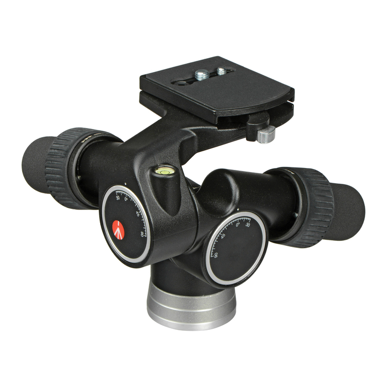
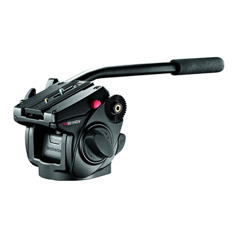
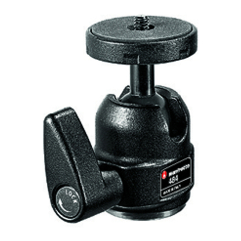
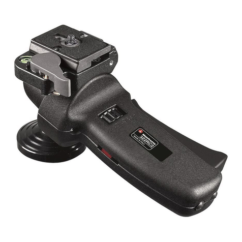
Rotule ball professionnelle pour les appareils photo moyen format.
INSTALLATION
Fixez la rotule au trépied en insérant la vis 3/8" du trépied dans le filetage "A" de la rotule.
Le socle de la colonne centrale des trépieds Manfrotto est équipé de trois vis "B" qui,
vissées à la base de la rotule, permettent un verrouillage encore plus sûr et efficace.
RETRAIT DU PLATEAU RAPIDE DE LA ROTULE
Le levier "N" est équipé d'un bouton de sécurité "O" empêchant le plateau "I" d'être
déverrouillé accidentellement. Pour déverrouiller le plateau "I" :
- tirez le levier de blocage "N" dans le sens indiqué par la flèche jusqu'à ce qu'il s'arrête.
- maintenez le levier "N" dans cette position semi-ouverte et appuyez sur le bouton "O" :
- cela débloque le levier "N" et vous pouvez alors l'ouvrir entièrement et libérer le plateau
rapide "I".
CHANGEMENT DE LA VIS DE L'APPAREIL
Le plateau rapide "I" est fourni avec une vis "L" de 1/4" et une vis "H" de 3/8"
Pour conserver la vis utile, procédez de la façon suivante :
- retirez le cache en caoutchouc "M" en appuyant dessus doucement avec un doigt,
- retirez la vis non utilisée de la rainure du plateau "I",
- remettez le bouchon en caoutchouc en place.
FIXATION DE L'APPAREIL AU PLATEAU
Fixez l'appareil photo au plateau "I" en vissant la vis "H" ou "L" du plateau dans l'orifice
fileté correspondant de l'appareil.
La vis "H" ou "L" coulisse dans la fente "R", ce qui vous permet d'aligner l'objectif de votre
appareil avec le plateau et de choisir la position la plus stable.
IMPORTANT !
Verrouillez l'appareil dans cette position en vissant solidement la vis "H" ou "L" dans
le plateau "I".
Remarque : La tête des vis "H" et "L" est fendue pour que celles-ci puissent être serrées
avec un pièce de monnaie.
FIXATION DE L'APPAREIL A LA ROTULE ET
Insérez le plateau rapide "I" (fig. 4) dans les queues d'aronde "U" de la base
supérieure de la rotule puis rabattez le plateau "I" sur la rotule jusqu'à entendre un
"clic" indiquant que le levier de blocage "N" a verrouillé le plateau.
Assurez-vous que le plateau rapide "I" (fig. 5) est correctement verrouillé en poussant
le leviez "N" complètement vers la gauche. Vérifiez que l'appareil est solidement fixé à
la rotule.
RETRAIT DE L'APPAREIL DE LA ROTULE
Lorsque vous devez retirer votre appareil de la rotule, tenez-le fermement d'une main
tandis que vous actionnez le levier "N" et le bouton "O" de l'autre.
UTILISATION
La rotule a un mouvement panoramique indépendant de la rotation de la boule.
La molette "E" bloque le mouvement panoramique. Afin de libérer le mouvement, débloquez
la molette "E" en la tournant sans les sens inverse des aiguilles d'une montre. Une fois que
la position souhaitée est réglée, bloquez la rotule en tournant complètement la molette "E"
dans le sens des aiguilles d'une montre. La molette "C" bloque la rotation de la boule.
Pour utiliser la rotule en toute sécurité, maintenez toujours d'une main votre appareil
lorsque vous débloquez la boule.
Afin de régler l'appareil, débloquez la rotation de la boule "D", en desserrant la molette "C"
et en la tournant dans le sens inverse des aiguilles d'une montre.
Ensuite, une fois que la position est réglée, bloquez la boule "D" en tournant complètement
la molette "C" dans le sens des aiguilles d'une montre. Le réglage de la friction de la boule
permet d'effectuer un contrôle très précis de la rotation de la rotule avant de la bloquer
totalement. Pour régler la friction, assurez vous que la boule "D" ne soit pas bloquée, (en
tournant la molette "B" dans le sens inverse des aiguilles d'une montre).
Puis, maintenez l'appareil d'une main et de l'autre faites tourner la bague "K" dans le sens
des aiguilles d'une montre pour augmenter la friction ou bien dans le sens inverse des
ainguilles d'une montre pour diminuer la friction (comme indiqué sur la bague).
En aucun cas la friction ne doit servir à bloquer l'appareil. Nous conseillons d'effectuer le
blocage de la boule "D" en serrant complètement la molette "C".
INTRODUCTION
A professional ball head designed for medium-format cameras.
SET UP
Assemble the head on the tripod using 3/8” female thread “A”.
The top plate on Manfrotto tripods are equipped with three set screws “B” which
clamp against the base of the head to ensure effective and secure locking.
REMOVE QUICK RELEASE PLATE FROM HEAD
The lever “N” is equipped with a safety button “O” to prevent the camera plate “I” from
accidentally being released.
To release the camera plate “I”:
- pull the locking lever “N” in the direction indicated by the arrow until it will go no further
- hold lever “N” in the above position and at the same time press button “O”
- this allows lever “N” to rotate further thus releasing the camera plate “I”
CHANGING PLATE CAMERA SCREW
The quick release plate “I” is supplied with 1/4” “L” and 3/8” “H” camera screw. The 1/4” is
mounted in the plate slot and the 3/8” screw is stored to the underside of the plate.
To replace the screws:
- remove the rubber cap “M” by carefully pressing it out with one finger
- insert the required screw in the slot in the camera plate “I”
- replace the rubber cap to prevent the screw being lost
ASSEMBLING CAMERA ON PLATE
Fix the camera onto the plate "I" by screwing home the camera screw "H" or “L” into the
cameras' threaded hole WITHOUT APPLYING FORCE.
The screw "H" or “L” slides along the slit "R" allowing you to align the camera lens with the
plate "I" and there by choose the best balance position.
IMPORTANT:
Secure the camera fully by screwing the screw "H" or "L" against plate “I”.
Note: The screws “H” and “L” have a grove in the head to enable them to be tightened with
a coin
MOUNTING THE CAMERA ON THE HEAD &
Insert the camera plate “I” (fig. 4) into the dovetail sides “U” on top of the head and
then press plate “I” downwards until locking lever “N” clicks and closes.
Make sure that plate “I” (fig. 5) is fully locked by pushing lever “N” all the way to the
left side and checking that the camera is fitted securely
REMOVE THE CAMERA FROM THE HEAD
Whenever the camera needs to be removed from the head, hold the camera securely
in one hand while operating locking lever “N” and safety lever “O” with the other.
USE
The head has panoramic and ball independent movements. The knob "E” locks the
panoramic movement. To release the movement, unlock knob “E” by rotating anticlockwise
Once the desired position is achieved, lock the head by turning knob "E" fully clockwise.
The knob "C” locks the ball movement.
To ensure that the ball head is used safety, always hold the camera with one hand
while releasing the ball.
To release the ball “D” for positioning the camera, unlock knob “C” by rotating anticlockwise
Once the desired position is achieved, lock the ball “D” by turning knob "C" fully clockwise.
The head incorporates a separate friction adjustment for the ball movement, which makes it
easier to control the positioning of the head before locking it off.
To adjust the friction ensures the ball “D” is not locked (rotating the locking knob “C”
anticlockwise). Then hold the camera in one hand and rotate with the other the ring “K”
clockwise to tighten the friction, anticlockwise to reduce the friction (as shown on the ring)
The friction does not allows the locking of the camera: we recommend to lock the ball “D”
by fully turning the knob “C”.
EINLEITUNG
Professioneller Kugelkopf für Mittelformatkameras.
ANBRINGUNG
Bringen Sie den Kugelkopf über seine 3/8"-Gewindebuchse auf dem Stativ an.
Die Kopfplatte von Manfrotto Stativen ist mit drei Stellschrauben "B" versehen, die
sicheren Sitz am Sockel des Kugelkopfes gewährleisten.
ABNEHMEN DER SCHNELLWECHSELPLATTE VOM KUGELKOPF
Der Hebel "N" besitzt eine Sicherung "O", die verhindert, dass sich die Kameraplatte "I"
ungewollt löst.
Zum Lösen der Kameraplatte "I"
- ziehen Sie den Klemmhebel "N" bis zum Anschlag in Pfeilrichtung;
- halten den Hebel "N" in dieser Stellung fest und drücken gleichzeitig Knopf "O";
- dadurch kann Hebel "N" weiter geschwenkt werden, so dass die Kameraplatte "I"
freigegeben wird.
WECHSELN DER KAMERASCHRAUBE
Die Schnellwechselplatte "I" wird mit einer Kameraschraube "L" (1/4") und einer Schraube
"H" (3/8") geliefert..
Zum Wechseln der Schrauben verfahren Sie wie folgt:
- Drücken Sie den Gummistopfen "M" vorsichtig mit einem Finger heraus.
- Setzen Sie die gewünschte Schraube in den Schlitz der Kameraplatte "I" ein.
- Bringen Sie den Gummistopfen wieder an, damit die Schraube nicht verloren geht.
ANSETZEN DER KAMERA AN DIE PLATTE
Befestigen Sie die Kamera an der Platte "I", indem Sie die Kameraschraube "H" bzw. "L"
OHNE GEWALTANWENDUNG in die Stativbuchse der Kamera schrauben.
Die Schraube "H" bzw. "L" kann zum Ausbalancieren der Ausrüstung in ihrem Schlitz "R"
verschoben werden.
ACHTUNG: Sorgen Sie für festen Sitz der Kamera, indem Sie Schraube "H" bzw. "L"
fest gegen Platte "I" anziehen.
Anmerkung: Die Schrauben "H" und "L" können mit einer Münze angezogen werden.
ANSETZEN DER KAMERA AN DEN KUGELKOPF UND
Setzen Sie die Kameraplatte "I" (Abb. 4) in die Schwalbenschwanzführung auf dem
Kugelkopf ein, und drücken Sie sie an, bis Klemmhebel "N" einrastet und verriegelt.
Vergewissern Sie sich, dass die Platte "I" (Abb. 5) zuverlässig fixiert ist, indem Sie
Hebel "N" an seinen linken Anschlag drücken und die Kamera auf festen Sitz prüfen.
ABNEHMEN DER KAMERA VOM KUGELKOPF
Wenn die Kamera vom Kugelkopf abgenommen werden muss, nehmen Sie sie fest in
eine Hand, während Sie mit der anderen den Klemmhebel "N" und den
Sicherungshebel "O" betätigen.
BEDIENUNG
Der Kopf verfügt über voneinander unabhängige Panorama- und Kugelbewegung.
Der Drehknopf "E" arretiert die Panoramabewegung. Um diese wieder lösen zu können,
drehen Sie den Drehknopf "E" gegen den Uhrzeigersinn. Sobald Sie die gewünschte
Einstellung erreicht haben, fixieren Sie diese durch vollständiges Drehen des Drehknopfes
"E" im Uhrzeigersinn. Der Drehknopf "C" arretiert die Kugelbewegung.
Halten Sie die Kamera immer mit einer Hand fest, wenn Sie die Kugelbewegung
lösen, damit die Kamera nicht Abstürzen kann.
Um die Kugel "D" für Kameraeinstellungen zu lösen, schrauben Sie den Drehknopf
"C" gegen den Uhrzeigersinn auf.
Sobald Sie die gewünschte Einstellung erreicht haben, fixieren Sie diese durch
vollständiges Drehen des Drehknopfes "C" im Uhrzeigersinn. Der Kugelkopf beinhaltet eine
zusätzliche Friktionskalibrierung für die Kugelbewegung, welche Ihnen das
Justieren der Einstellungen vereinfacht.
Um die Friktion einstellen zu können, versichern Sie sich, dass die Kugel "D" nicht blockiert
ist. Halten Sie dann die Kamera mit einer Hand und drehen Sie das Rad "K" mit der
anderen gegen den Uhrzeigersinn, um die Friktion zu verstärken, oder
im Uhrzeigersinn, um sie zu reduzieren (wie es auf dem Rad "K" angegeben ist).
Nur Friktion, auch eine starke Einstellung, reicht nicht aus, um die Kamera zu fixieren:
benützen Sie deshalb zur Blockierung der Kugelbewegung immer auch den Drehknopf "C".
1
2
3
5
6
4
1
1
2
3
45
6
1
1
1
2
3
45
6
1
1
1
2
3
45
6
1

