manuals.online logo
Brands
  1. Home
  2. •
  3. Brands
  4. •
  5. Manfrotto
  6. •
  7. Camera Accessories
  8. •
  9. Manfrotto 560B User manual

Manfrotto 560B User manual

EINFÜHRUNG
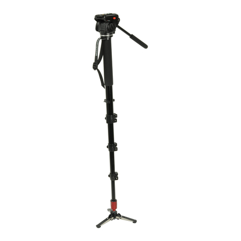
Hergestellt für kompakte Mini DV und HDV Kameras, ist das Fluid Video Einbein-Stativ
leicht zu transportieren und besitzt klappbare Füsse aus rostfreiem Stahl für zusätzliche
Stabilität auf unebenem Untergrund.
HAUPTMERKMALE
• Fluid-Schwenkbasis mit klappbaren Beinen
• Schnelle Action, Klappbeine werden gesperrt
• Kippbarer Kopf
AUFSTELLEN
1
Um die Höhe des Einbein-Stativs einzustellen, drehen Sie den Hebel “A” an der Arretierung
“B”. Wenn die gewünschte Höhe eingestellt wurde, sperren Sie den Hebel “A” wieder.
ENTFERNEN DER SCHNELLSPANNPLATTE VOM KOPF
2
Um die Kameraplatte “G“ zu entfernen, ist es nötig, den Hebel “H“ in Pfeilrichtung zu
öffnen.
Der Hebel "H" kann nicht geöffnet werden, wenn der Sicherheitshebel "I" in geschlossen
ist. Um die Sicherheitssperre zu lösen, drehen Sie den Sicherheitshebel Hebel "I" voll in
Pfeilrichtung und drehen dann den Hebel "H", bis der Arretierbolzen "L", der den Hebel "H"
blockiert, nach oben schnellt.
MONTAGE DES CAMCORDERS AN DIE PLATTE
3
&
4
Sollte Ihr Camcorder eine Öffnung für einen VHS-Stift haben, werden Sie den Stift "P" in
das Loch "X" führen müssen. Ziehen Sie den Stift “P” (fig. 3) von oben heraus, um ihn zu
bewegen. Wenn der Camcorder keine Öffnung für den VHS-Stift besitzt, entfernen Sie
einfach nur den Stift “P”. Befestigen Sie den Camcorder auf der Platte "G" (fig. 4), indem
Sie die Schraube "M" in das Gewinde der Kamera schrauben, OHNE KRAFTAUFWAND.
Drehen Sie dazu den Ring "Q". Bevor Sie den Camcorder vollständig fixieren, richten Sie
das Objektiv des Camcorders am Stift “P“ aus, wenn geeignet, oder an der Markierung
“LENS" an der Kameraplatte “G“, wie in der Figur 4 dargestellt. Vergewissern Sie sich vor
Gebrauch, dass die Kamera sicher mit der Platte verbunden ist.
MONTAGE DER KAMERA AUF DEM KOPF
5
&
6
Führen Sie die Kameraplatte "G" (fig. 5) mit der richtigen Kante "Z" gegen den Sperrhebel
"H" auf der Oberseite des Kopfes ein, bis der Sperrhebel klickt und sperrt. Achten Sie
auf die richtige Position der Platte “G” wie oben beschrieben, um eine sichere Montage
der Kamera zu erreichen. Drehen Sie den Sicherungshebel "I" gegen den Uhrzeigersinn.
Vergewissern Sie sich, dass die Platte “G“ (fig. 6) vollkommen blockiert ist. Schwenken Sie
dazu den Hebel “H“ und kontrollieren Sie nochmals, dass die Kamera sicher auf dem Kopf
sitzt.
ENTFERNEN DER KAMERA VOM KOPF
7
Wenn die Kamera vom Kopf genommen werden muss, lösen Sie den Sicherungshebel "I".
Halten Sie die Kamera mit einer Hand fest und lösen Sie mit der anderen den Hebel "H".
KLAPPEN DER BASIS
8
&
9
Öffnen (fig. 8): öffnen Sie die 3 Beine “S”, indem Sie sie, wie in der fig. 7 dargestellt,
aufklappen.
Schliessen (fig. 9): Ziehen Sie den Stift “H”, wie in der Figur gezeigt, und klappen Sie
gleichzeitig die Beine “S” ein.
GEBRAUCH
10
Das Einbein-Stativ ist mit einer Fluid-Basis "X" ausgestattet. Dies vermeidet Vibrationen
während der Schwenkbewegung (siehe fig. 11).
ANMERKUNG
11
Die Basis erlaubt es, das Equipment aus der vertikalen Achse heraus zu kippen (siehe fig. 11):
Wir empfehlen, das Einbein-Stativ nicht alleine stehen zu lassen, sondern immer mit
einer Hand zu halten.
Das Einbein-Stativ ist mit einem kippbaren Kopf ausgestattet: dies erlaubt es, vor
der Aufnahme den Aufnahmewinkel einzustellen, um die vertikale Panorama-Achse
beizubehalten.
WARTUNG
12
Wenn die Kugel “W” nach dem Einsatz zu lose wird, können Sie die richtige Reibung wieder
einstellen, indem Sie die Einstellschraube “Y” (siehe fig. 12) leicht nachziehen – bitte lösen
Sie nicht die zwei anderen Schrauben “U”.
INTRODUCTION
Conçu pour des caméscopes compacts mini DV et HDV, le monopode Fluid Video est
extrêmement compact et est équipé d’une base repliable en inox pour une stabilité accrue
sur terrain irrégulier.
CARACTÉRISTIQUES PRINCIPALES
• Base fluide panoramique avec pieds pliants
• Leviers de blocage rapide des sections
• Rotule inclinable
INSTALLATION
1
Pour régler la hauteur du monopode, ouvrez les leviers de blocages "A" situés sur les
bagues "B". Une fois votre monopode réglé à la hauteur souhaitée, bloquez les sections à
l'aide des leviers "A".
RETRAIT DU PLATEAU RAPIDE DE LA ROTULE
2
Pour retirer le plateau rapide "G", ouvrez d'abord le levier de blocage "H".
Le levier "H" ne peut être ouvert tant que le levier de sécurité secondaire "I" est en position
verrouillée. Tournez entièrement le levier de sécurité secondaire "I" dans le sens de la
flèche illustrée puis ouvrez le levier "H". Le cliquet "L" doit émettre un "clic" lorsque le levier
"H" est déverrouillé.
FIXATION DU CAMÉSCOPE AU PLATEAU RAPIDE
3
&
4
Si votre caméscope est doté d'un orifice pour ergot VHS anti-rotation, insérez l'ergot "P"
(fig. 1) dans le trou "X". Pour retirer l'ergot "P" (fig. 3), poussez-le par en dessous. Si le
caméscope n'est pas muni d'un orifice de fixation d'ergot VHS, retirez simplement l'ergot
"P".
Fixez le caméscope au plateau rapide "G" (fig. 4) en vissant la vis de fixation "M" dans le
filetage du caméscope SANS FORCER, en vous aidant pour cela de l'anneau "Q".
Avant de bloquer ce montage entièrement, alignez l'objectif avec l'ergot "P" si c'est
possible, ou avec l'inscription "LENS" du plateau "G" le cas échéant (fig. 4).
Assurez-vous que le caméscope est parfaitement fixé au plateau rapide avant utilisation.
FIXATION DU CAMÉSCOPE À LA ROTULE
5
&
6
Insérez le plateau "G" (fig. 5) avec le côté "Z" du côté du levier de blocage "H" sur le
dessus de la rotule, jusqu'à ce qu'un "clic" signale que le plateau est correctement
verrouillé. Prenez garde d'insérer le plateau "G" dans le bon sens afin de garantir qu'il sera
correctement fixé. Tournez le levier de sécurité "I" dans le sens inverse des aiguilles d'une
montre pour le verrouiller.
Assurez-vous que le plateau rapide "G" (fig. 6) est correctement fixé en poussant le levier
"H" et vérifiez que l'appareil est solidement fixé à la rotule.
RETRAIT DU CAMÉSCOPE DE LA ROTULE
7
Lorsque vous devez retirer votre caméscope de la rotule, déverrouillez le levier "I", puis, en
tenant fermement votre appareil d'une main, actionnez le levier "H" de l'autre.
BASE REPLIABLE
8
&
9
Pour ouvrir la base (8) : ouvrez les 3 pieds "S" (fig. 7).
Pour refermer la base (9) : poussez le bouton "T" (fig. 6) pour replier chaque pied "S".
UTILISATION
10
Ce monopode est équipé d’une base fluide "X", qui amortit les vibrations pendant les
mouvements panoramiques (fig. 11).
REMARQUE
11
Cette base permet d'incliner le monopode dans toutes les directions (fig. 11).
Nous vous recommandons toutefois de toujours tenir le monopode d'une main.
Ce monopode est équipé d'une rotule à inclinaison verticale qui permet de pré-régler
l'angle de prise de vue avant de commencer à filmer afin de maintenir l'axe panoramique
vertical pendant l'utilisation.
ENTRETIEN
12
Si la boule "W" de la base fluide est trop lâche, vous pouvez en régler la friction en
resserrant légèrement la vis de réglage "Y" (fig. 12). Attention, ne dévissez pas les deux
autres vis "U". 166 cm 0,7 kg 2 kg
65.35” 1.54 lbs 4.4 lbs
INSTRUCTIONS
560B
Cod. 560,12 - 11/07 Copyright © 2006 Manfrotto Bassano Italy
INTRODUZIONE
Progettato per le videocamere compatte mini DV e HDV, questo monopiede fluido video
risulta particolarmente portatile ed offre piedini pieghevoli in acciaio per una stabilità
aggiuntiva su terreni irregolari.
CARATTERISTICHE PRINCIPALI:
• Base panoramica fluida con piedini pieghevoli
• Messa in opera rapida, bloccaggi delle sezioni a leva
• Testa inclinabile
PREPARAZIONE
1
Per regolare l’altezza del monopiede, ruotare la leva “A” sul manicotto “B”. Ottenuta
l’altezza desiderata, bloccare la leva “A”.
RIMOZIONE DELLA PIASTRA RAPIDA DALLA TESTA
2
Per rimuovere la piastra “G” è necessario aprire la leva “H”. Questa non può essere aperta
mentre la sicura “I” è in posizione di blocco. Per rimuovere il blocco di sicurezza, ruotare
completamente la sicura “I” nella direzione indicata dalla freccia, quindi ruotare la leva “H”
finché il piolino “L” scatta in alto mantenendo aperta la leva “H”.
MONTAGGIO DELLA VIDEOCAMERA SULLA PIASTRA
3
&
4
Se la videocamera dispone di foro antirotazione, sarà opportuno portare il piolino “P” (fig.
1) nel foro “X”. Premere il piolino “P” (fig. 3) dall’alto per spostarlo. Se la videocamera non
dispone di foro antirotazione, basterà semplicemente rimuovere il piolino “P”.
Fissare la videocamera sulla piastra “G” (fig. 4) avvitando la vite “M” nel foro filettato
dell’apparecchio, aiutandosi con l’anello “Q”, MA SENZA STRINGERE LA VITE DEL TUTTO.
Prima di serrare a fondo la vite, allineare l’obiettivo della videocamera col piolino “P”
oppure con l’indicazione “LENS” sulla piastra rapida “G” come mostrato in figura 4.
Prima dell’uso, occorre accertarsi che la videocamera sia saldamente fissata sulla piastra
rapida.
MONTAGGIO DELLA VIDEOCAMERA SULLA TESTA
5
&
6
Inserire la piastra “G” (fig. 5) sulla testa, con l’incastro “Z” bloccato dalla leva “H”
verificando che sia avvenuto lo scatto di chiusura della leva stessa. Per avere un bloccaggio
sicuro rispettare la corretta posizione della piastra “G” descritta più sopra. Ruotare la sicura
“I” in senso antiorario.
Accertarsi che la piastra “G” (fig. 6) sia perfettamente bloccata premendo la leva “H” e
verificando che la videocamera sia saldamente fissata alla testa.
RIMOZIONE DELLA VIDEOCAMERA DALLA TESTA
7
Quando occorre separare la videocamera dalla testa, reggere saldamente la videocamera
con una mano mentre con l’altra mano si sblocca prima la sicura “I” e poi si aziona la leva
di blocco “H”.
BASE PIEGHEVOLE
8
&
9
Apertura (8): Estendere i 3 piedini “S” divaricandoli come mostrato in figura 7.
Chiusura (9): spostare la sicura “T” come mostrato in figura mentre si ripiega ciascun
piedino “S”.
USO
10
Questo monopiede prevede una base fluida “X” che consente di eliminare le vibrazioni nel
corso dei movimenti in panoramica (vedere figura 10).
NOTA
11
La base consente anche l’inclinazione dell’apparecchio rispetto alla verticale (vedere figura 11):
Si raccomanda di non lasciare che il monopiede si sostenga soltanto sulla propria
base, ma di reggerlo sempre con una mano.
Il monopiede è dotato di testa inclinabile che consente di preimpostare l’angolo di ripresa
per mantenere verticale l’asse di panoramica durante l’uso.
MANUTENZIONE
12
Se la sfera “W” si dovesse allentare con l’uso, si potrà ripristinare il corretto frizionamento
stringendo leggermente la vite di regolazione “Y” (vedere figura 12) – si raccomanda di non
svitare le altre due viti “U”
INTRODUCTION
Designed for compact mini DV and HDV cameras, the Fluid Video Monopod is highly
portable and offers fold up stainless steel feet for additional stability on uneven ground.
KEY FEATURES
• Fluid pan base with folding legs
• Rapid action, lever leg extension locks
• Tilt head
SET UP
1
To adjust the height of the monopod, rotate lever “A” on the locking collar “B”.
When the required height is achieved, lock lever “A”.
REMOVE QUICK RELEASE PLATE FROM HEAD
2
To remove plate “G” it is necessary to open the lever “H”.
The lever “H” can not be opened whilst the safety lever “I” is in closed position.
To remove the safety catch, rotate safety lever “I” fully in the direction of the arrow and then
rotate the lever “H” until peg “L” clicks up holding the open the lever “H”.
ASSEMBLING CAMCORDER ON PLATE
3
&
4
If your camcorder has a hole for a VHS pin, you will need to move pin “P” (fig. 1) into hole
“X”. Push the pin “P” (fig. 3) out from above to move it. If the camcorder doesn’t have the
VHS pin hole, simply remove the pin “P”.
Fix the camcorder onto plate “G” (fig. 4) by screwing home camera screw “M” into the
camera’s threaded hole WITHOUT APPLYING FORCE, using the ring “Q”.
Before fully locking, align the camcorder lens with pin “P” if appropriate, or with the “LENS”
marking on the camera plate “G” as shown in figure 4.
Please ensure you have securely locked the camcorder on to the release plate before use.
MOUNTING THE CAMERA ON THE HEAD
5
&
6
Insert the camera plate “G” (fig. 5) with the appropriate back edge “Z” against the locking
lever “H” on top of the head until locking lever clicks and closes. Respect the right position
of the plate “G” described above to achieve a safe locking of the camera. Rotate the safety
lever “I” anticlockwise .
Make sure that plate “G” (fig. 6) is fully locked by pushing lever “H” and checking that the
camera is fitted securely to the head.
REMOVE THE CAMERA FROM THE HEAD
7
Whenever the camera needs to be removed from the head, release the safety lever “I” and
then hold the camera securely in one hand while operating locking lever “H” with the other.
FOLDING BASE
8
&
9
How to open (8): open the 3 legs “S” by spreading them as shown in figure 7.
How to fold (9): pull the pin “T” as shown in figure and at the same time fold each leg “S”.
USE
10
The monopod is designed with a fluid base “X”: it allows to eliminate vibration during the
pan movement (see figure 10).
NOTE
11
The base allows to tilt the equipment out from vertical axis (see figure 11):
We recommend not to leave the monopod standing alone but always keep it with
your hand.
The monopod is supplied with tilt head: it allows to preset the shooting angle before to start
in order to maintain the panoramic axis vertical during use.
MAINTENANCE
12
If the ball “W” becomes too free after using, you can reach again the right friction by
tightening a bit the adjustment screw “Y” (see figure 12) – please do not unscrew the other
two screws “U”.
A
B
X
P
A
B
A
B
G
MQ
H
L
H
I
S
S
T
X
UUY
W
SS
P
I
G
22
11
1
1
33
H
Z
I
G
H
2
1G
1
5 6
2
7
8
9
10
11 12
3
4

Other Manfrotto Camera Accessories manuals

Manfrotto 524AX User manual

Manfrotto

Manfrotto 524AX User manual

Manfrotto 554 User manual

Manfrotto

Manfrotto 554 User manual

Manfrotto 475 User manual

Manfrotto

Manfrotto 475 User manual

Manfrotto 627 User manual

Manfrotto

Manfrotto 627 User manual

Manfrotto 724B User manual

Manfrotto

Manfrotto 724B User manual

Manfrotto 545B User manual

Manfrotto

Manfrotto 545B User manual

Manfrotto 535 User manual

Manfrotto

Manfrotto 535 User manual

Manfrotto MT190GOA4 User manual

Manfrotto

Manfrotto MT190GOA4 User manual

Manfrotto MVM500A User manual

Manfrotto

Manfrotto MVM500A User manual

Manfrotto 303SPH User manual

Manfrotto

Manfrotto 303SPH User manual

Manfrotto 808RC4 User manual

Manfrotto

Manfrotto 808RC4 User manual

Manfrotto MKBFRLA-BH User manual

Manfrotto

Manfrotto MKBFRLA-BH User manual

Manfrotto MVG220 User manual

Manfrotto

Manfrotto MVG220 User manual

Manfrotto 132 User manual

Manfrotto

Manfrotto 132 User manual

Manfrotto 494 User manual

Manfrotto

Manfrotto 494 User manual

Manfrotto 7302YB User manual

Manfrotto

Manfrotto 7302YB User manual

Manfrotto MVMFXPRO2W User manual

Manfrotto

Manfrotto MVMFXPRO2W User manual

Manfrotto ART. 190CXPRO3 User manual

Manfrotto

Manfrotto ART. 190CXPRO3 User manual

Manfrotto 438 User manual

Manfrotto

Manfrotto 438 User manual

Manfrotto MVHN12AH User manual

Manfrotto

Manfrotto MVHN12AH User manual

Manfrotto 303 User manual

Manfrotto

Manfrotto 303 User manual

Manfrotto MVM450A User manual

Manfrotto

Manfrotto MVM450A User manual

Manfrotto 501HDV User manual

Manfrotto

Manfrotto 501HDV User manual

Manfrotto MVG460 User manual

Manfrotto

Manfrotto MVG460 User manual

Popular Camera Accessories manuals by other brands

PROAIM PT-GOLD Assembly manual

PROAIM

PROAIM PT-GOLD Assembly manual

Intel RAID AXXRSBBU6 user guide

Intel

Intel RAID AXXRSBBU6 user guide

Moog Videolarm FCH360C2W Installation and operation instructions

Moog Videolarm

Moog Videolarm FCH360C2W Installation and operation instructions

Sanyo CR17335HE-R Specifications

Sanyo

Sanyo CR17335HE-R Specifications

Camlink CL-LED48 user manual

Camlink

Camlink CL-LED48 user manual

EEMB LP8867220F specification

EEMB

EEMB LP8867220F specification

Bioenno Power BLF-24100LB user manual

Bioenno Power

Bioenno Power BLF-24100LB user manual

Parkside 354677 2010 Translation of the original instructions

Parkside

Parkside 354677 2010 Translation of the original instructions

Ikelite TG-1 quick start guide

Ikelite

Ikelite TG-1 quick start guide

RedEarth SunRise SRS-1 NS Series installation manual

RedEarth

RedEarth SunRise SRS-1 NS Series installation manual

Kaiser KR90 operating instructions

Kaiser

Kaiser KR90 operating instructions

Glidecam CENTURION manual

Glidecam

Glidecam CENTURION manual

Energizer 395 Product data sheet

Energizer

Energizer 395 Product data sheet

Ikan PT4500S quick start guide

Ikan

Ikan PT4500S quick start guide

Big Game Treestands The Apex CR9000 instruction manual

Big Game Treestands

Big Game Treestands The Apex CR9000 instruction manual

milleteknik NOVA FLX M quick start guide

milleteknik

milleteknik NOVA FLX M quick start guide

Tokina MONOFOCAL LENS TC0614AI specification

Tokina

Tokina MONOFOCAL LENS TC0614AI specification

Luma Surveillance LUM-MNT-CAP-IPPTZ-WH installation manual

Luma Surveillance

Luma Surveillance LUM-MNT-CAP-IPPTZ-WH installation manual

manuals.online logo
manuals.online logoBrands
  • About & Mission
  • Contact us
  • Privacy Policy
  • Terms and Conditions

Copyright 2025 Manuals.Online. All Rights Reserved.