manuals.online logo
Brands
  1. Home
  2. •
  3. Brands
  4. •
  5. Manfrotto
  6. •
  7. Camera Accessories
  8. •
  9. Manfrotto 804RC2 User manual

Manfrotto 804RC2 User manual

INTRODUCCION
Rótula profesional de 3 ejes, ideal para cámaras de 35 mm, SLR y de medio formato.
CARACTERISTICAS PRINCIPALES
• Mandos de diseño ergonómico
• Plato rápido con seguridad adicional
• Se proporciona con un dispositivo innovador que ayuda a soportar el peso de la cámara
sobre el eje de inclinación.
La rótula se entrega con dos asas “A” y “B” desmontada. Monte las asas como se muestra
en la fig. 1. Los dos tornillos “N” se insertan sólo cuando la rótula está montada sobre el
trípode.
PREPARACION
ACOPLAMIENTO DE LA ROTULA AL TRIPODE
Adapte la rótula al trípode/monopie etc. utilizando la rosca hembra “E” de 3/8”.
El plato superior de los trípodes Manfrotto viene equipado con tres tornillos hundidos
“F” que presionan contra la base de la rótula para garantizar un bloqueo efectivo y
seguro.
QUITE EL PLATO DE LIBERACIÓN RÁPIDO DE LA RÓTULA
Para quitar el plato “G” es necesario abrir la palanca “H”.
La palanca “H” no se podrá abrir mientras el seguro “I” este´cerrado.
Para abrir el seguro, gire la palanca “H” y presione hacia debajo el seguro “I”
Hasta que la palanca “H” alcance la posición de parada.
ACOPLAR LA CAMARA AL PLATO
Fije la cámara al plato “G” enroscando el tornillo “M” en la rosca hembra que lleve la cámara
SIN APLICAR FUERZA utilizando el anillo “Q”. Antes de bloquear del todo alinee la cámara
con la marca “LENS” en el plato “G”
Por favor, asegúrese de haber bloqueado la cámara segura sobre el plato antes de
trabajar.
MONTANDO LA CÁMARA EN LA RÓTULA &
Presione el anillo “Q” hasta que esté plano contra el plato “G”.
Inserte el plato “G” (fig. 4) sobre la parte superior de la rótula hasta que la palanca de
bloqueo“H” haga click y cierre.
Asegúrese que el plato “G” (fig. 5) está completamente bloqueado presionando la
palanca “H” y comprobando que la cámara está asegurada sobre la rótula.
QUITE LA CÁMARA DE LA RÓTULA
Cuando necesite quitar la cámara de la rótula, mantenga la cámara firmemente con
una mano mientras gira la palanca “H” y presiona hacia abajo el seguro “I” hasta que
la palanca “H” alcance la posición de parada.
USO
Los tres mandos “A” “B” y “C” controlan los movimientos panorámicos, de lado a lado,
hacia adelante y atras.
El mando “A” controla un giro panorámico de 360°
El mando “B” controla el movimiento de nivelado lateral entre +90° y –30°
El mando “C” controla el movimiento de inclinación vertical entre +90° y –30°
El girar los mandos en contra del sentido de las manecillas del reloj permite mover la rótula
en la posición requerida y luego se bloquea en dicha posición girando el mando como las
manecillas del reloj.
1
2
3
4 5
6
1
INTRODUZIONE
Testa a 3 assi ideale per fotocamere di piccolo e medio formato
CARATTERISTICHE
• Manopole di comando ergonomiche
• Piastra ad aggancio rapido con dispositivo secondario di sicurezza
• Equipaggiata con un innovativo dispositivo che aiuta a sostenere il peso della fotocamera
sull’asse di inclinazione frontale (TILT).
La testa é fornita con due impugnature “A” e “B” smontate. Assemblare le impugnature
come mostrato in fig. 1. Le due viti “N” sono presenti soltanto se la testa viene fornita
montata su un treppiede.
PREPARAZIONE
MONTAGGIO DELLA TESTA SUL TREPPIEDE
Montare la testa sul treppiede utilizzando l’attacco femmina “E” da 3/8” (fig. 1).
I treppiedi Manfrotto sono dotati di tre grani “F” da avvitare contro la base della testa
per un bloccaggio efficace e sicuro.
SMONTAGGIO DELLA PIASTRA RAPIDA DALLA TESTA
Per rimuovere la piastra “G” é necessario aprire la leva “H”.
La leva “H” non può essere aperta mentre la sicura “I” é in posizione chiusa.
Per disattivate il blocco di sicurezza, ruotare la leva “H” e premere la sicura “I” per
consentire la totale apertura della leva “H”.
MONTAGGIO DELLA FOTOCAMERA SULLA PIASTRA
Per fissare la fotocamera alla piastra “G” avvitare, SENZA FORZARE, la vite d’attacco “M”
nel foro filettato della fotocamera fino al fondo del filetto agendo sull’anello “Q”.
Prima del bloccaggio definitivo, allineare l’obiettivo della fotocamera con la scritta “LENS”
visibile sotto alla piastra “G”
Bloccare definitivamente la fotocamera avvitando la vite “M” mediante l’anello “Q”
MONTAGGIO DELLA FOTOCAMERA SULLA TESTA &
Premere l’anello “Q” in modo che stia appoggiato alla piastra “G”.
Inserire la piastra “G” (fig. 4) nell’apposita sede sulla testa fino ad avere lo scatto e il
bloccaggio sicuro della leva di bloccaggio “H”.
Accertarsi che la piastra “G” (fig. 5) sia inserita correttamente premendo la leva “H” e
controllando che la fotocamera risulti assicurata saldamente alla testa.
SMONTAGGIO DELLA FOTOCAMERA DALLA TESTA
Per rimuovere la fotocamera dalla testa, tenere saldamente con una mano la
fotocamera mentre si ruota la leva “H” e si preme la sicura “I” fino alla totale apertura
della leva “H”.
USO
I movimenti della testa sono controllati dalle tre manopole “A” “B” e “C”
La manopola “A” comanda il movimento panoramico a 360°
La manopola “B” comanda il movimento di livellamento laterale tra +90° e -30°
La manopola “C” comanda il movimento d’inclinazione verticale tra +90° e -30°
Per ogni movimento è necessario svitare la manopola fino a liberare il movimento relativo.
Raggiunta la posizione voluta avvitare la manopola fino ad ottenere un bloccaggio efficace.
1
2
3
4 5
6
1
Cod. 804,31 - 05/08 Copyright © 2006 Manfrotto Bassano Italy
12 cm 0,79 kg 4 kg
4.7” 1.73 lbs 8.8 lbs
INSTRUCTIONS
804RC2
INTRODUCTION
Rotule professionnelle 3D idéale pour les appareils 35 mm et moyens formats.
CARACTERISTIQUES
• Poignées de contrôle ergonomiques
• Système de plateau rapide avec double sécurité
• Dispositif innovant d’assistance du contrôle de la bascule avant/arrière de l’appareil photo
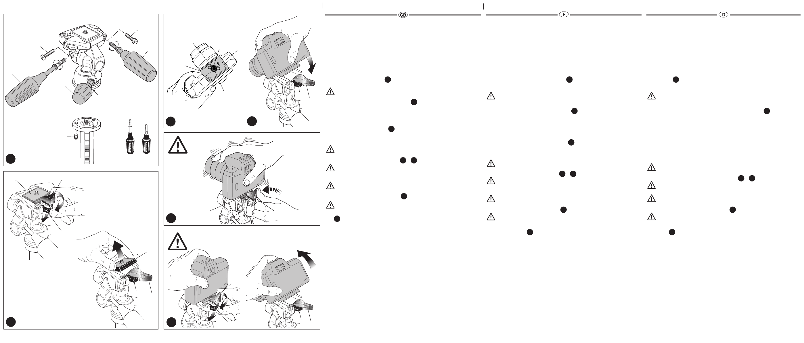
La rotule est livrée avec les deux poignées “A” et “B” non montées. Montez les poignées
de la manière illustrée à la fig. 1. Les vis “N” ne sont insérées que lorsque la rotule est livrée
montée sur un trépied.
PREPARATION
MONTAGE DE LA ROTULE SUR LE TREPIED
Montez la rotule sur le trépied ou monopode etc. en la vissant grâce au pas de vis femelle
3/8” “E”.
Les disques de base des trépieds Manfrotto sont dotés de trois vis sans têtes “F”, qui
une fois qu’elles sont en butée sur la base de la rotule évitent son desserrage et en
assurent sa parfaite fixation.
RETRAIT DU PLATEAU RAPIDE DE LA ROTULE
Pour retirer le plateau rapide “G”, ouvrez d’abord le levier de blocage “H”.
Le levier “H” ne peut être ouvert tant que le levier de verrouillage secondaire “I” est en
position verrouillée.
Pour déverrouiller cette sécurité, tournez le levier “H” tout en appuyant sur le levier “I” jusqu’à
ce que le levier “H” atteigne la butée.
MONTAGE DE L’APPAREIL SUR LE PLATEAU
Fixez le l’appareil sur le plateau “G” en vissant la vis “M” dans le trou fileté SANS FORCER
avec l’anneau “Q”. Avant de bloquer l’appareil, aligner parfaitement l’appareil avec le “LENS”
indiqué sur le plateau “G”.
Assurez vous que vous avez bien fixé l’appareil sur le plateau avant toute utilisation
FIXATION DE L’APPAREIL A LA ROTULE &
Baissez l’anneau “Q” de façon à ce qu’il soit à plat contre le plateau rapide “G”.
Insérez le plateau “G” (fig. 4) dans l’adaptateur de plateau de la rotule jusqu’à ce qu’un
“clic” indique que le levier “H” a bloqué le plateau.
Assurez-vous que le plateau rapide “G” (fig. 5) est correctement fixé en poussant le
levier “H” et vérifiez que l’appareil est solidement fixé à la rotule.
RETRAIT DE L’APPAREIL DE LA ROTULE
Lorsque vous devez retirer votre appareil de la rotule, tenez-le fermement d’une main
tandis que vous tournez le levier “H” tout en appuyant sur le levier de sécurité “I”
jusqu’à ce que le levier “H” atteigne la butée.
MODE D’UTILISATION
Les trois poignées “A” “B” et “C” contrôlent le mouvement panoramique, la bascule avant/
arrière et la bascule latérale.
La poignée “A” permet de contrôler le mouvement panoramique 360°.
La poignée “B” permet de contrôler la bascule latérale de + 90° et – 30°
La poignée “C” permet de contrôler la bascule avant / arrière de + 90° et –30°.
Desserrez les poignées en les tournant dans le sens inverse des aiguilles d’une montre pour
régler et positionner la rotule, ensuite bloquez la en tournant les poignées dans le sens des
aiguilles d’une montre.
1
2
3
4 5
6
1
EINFÜHRUNG
Professioneller 3D Fotoneigekopf für 35 mm und Mittelformatkameras.
AUSSTATTUNGSMERKMALE
• Ergonomische Blockiergriffe
• Schnellspannmechanismus mit Zusatzsicherung
• Innovative Konstruktion unterstützt den Ausgleich des Kameragewichts sowohl in der
Neigungs- als auch der Horizontalachse.
Der Stativkopf wird mit abgenommenen Handgriffen “A” und “B” geliefert. Diese werden
gemäß Abb. 1 angesetzt. Die beiden Schrauben “N” sind nur montiert, wenn der Stativkopf
mit einem Stativ verbunden zur Auslieferung kommt.
AUFSTELLEN
Setzen sie den Kopf auf ein Ein- oder Dreibeinstativ auf und benützen sie dazu die 3/8”
Schraube “E” auf der Unterseite.
Die Kopfauflageplatte von Manfrotto Stativen ist mit den Blockierschrauben “F”
ausgerüstet, welche ein unerwünschtes Losdrehen des Kopfes verhindern, wenn sie
korrekt angezogen sind.
ABNEHMEN DER SCHNELLWECHSELPLATTE VOM STATIVKOPF
Zum Abnehmen der Platte “G” muss Hebel “H” gelöst werden.
Dies ist jedoch nur möglich, wenn sich der Sicherungshebel “I” in geschlossener Stellung
befindet.
Zum Lösen der Sicherung betätigen Sie Hebel “H” und drücken den Sicherheitshebel “I”, bis
sich Hebel “H” am Anschlag befindet.
AUFSETZEN DER KAMERA AUF DIE SCHNELLSPANNPLATTE
Um die Kamera auf der Platte “G” zu befestigen, schrauben Sie die Schraube “M” OHNE
KRAFTANWENDUNG in das Gewinde der Kamera, indem Sie den Ring “Q” drehen. Bevor
Sie die Platte vollständig fixieren, richten Sie die Markierung “LENS” auf der Unterseite der
Kameraplatte “G” zum Objektiv aus (Objektivachse).
Versichern Sie sich vor Gebrauch, dass die Kamera sicher mit der Platte verbunden ist.
AUFSETZEN DER KAMERA AUF DEN STATIVKOPF &
Legen Sie Ring “Q” an Platte “G” an. Schieben Sie die Kameraplatte “G” (Abb. 4) auf
den Stativkopf, bis der Sicherheitshebel “H” einrastet.
Vergewissern Sie sich, dass die Platte “G” (Abb. 5) sicher verriegelt ist, indem Sie
Hebel “H” drücken und prüfen, ob die Kamera fest mit dem Stativkopf verbunden ist.
ABNEHMEN DER KAMERA VOM STATIVKOPF
Zum Abnehmen der Kamera vom Stativkopf nehmen Sie die Kamera fest in eine
Hand und betätigen Hebel “H” unter gleichzeitigem Druck auf den Sicherheitshebel
“I”, bis “H” seinen Anschlag erreicht.
GEBRAUCH
Die drei Blockiergriffe “A”, “B” “C” dienen zur Kontrolle und Arretierung der drei Neige- und
Schwenkebenen:
Blockiergriff “A” zur Verstellung der 360° Panoramabewegung.
Blockiergriff “B” zur Verstellung der seitlichen Kippbewegung von +90° bis -30°.
Blockiergriff “C” zur Verstellung der Neigebewegung von +90° bis -30°.
Drehen Sie den Blockiergriff im Gegenuhrzeigersinn um die Bewegungen zu lösen und
auszuführen.
Ziehen Sie den Blockiergrimm im Uhrzeigersinn an, um die Bewegung zu blockieren.
1
2
4 5
6
1
INTRODUCTION
Professional 3-axis head ideal for 35mm SLR and medium formats cameras.
KEY FEATURES
• Ergonomically designed control handles
• Quick release plate with secondary security
• Supplied with innovative device that helps to support camera weight on tilt axis.
The head is supplied with its two handgrips “A” and “B” dismantled.
Assemble the handgrips as shown in fig. 1. The two screws “N” are inserted only when the
head is shipped mounted on a tripod.
SET UP
ASSEMBLING HEAD ON TRIPOD
Assemble the head on the tripod using 3/8” female thread “E”.
The top plate on Manfrotto tripods are equipped with three set screws “F” which
clamp against the base of the head to ensure effective and secure locking.
REMOVE QUICK RELEASE PLATE FROM HEAD
To remove plate “G” it is necessary to open the lever “H”.
The lever “H” can not be opened whilst the safety lever “I” is in closed position.
To remove the safety catch, rotate the lever “H” and push down safety lever “I” until the lever
“H” reaches the stop.
ASSEMBLING CAMERA ON PLATE
Fix the camera onto plate “G” by screwing home camera screw “M” into the camera’s
threaded hole WITHOUT APPLYING FORCE, using the ring “Q”.
Before fully locking, align the camera with the “LENS” marking on the plate “G”.
Please ensure you have securely locked the camera on to the release plate before use
MOUNTING THE CAMERA ON THE HEAD &
Push the ring “Q” so that it is flat against the plate “G”.
Insert the camera plate “G” (fig. 4) on top of the head until locking lever
“H” clicks and closes.
Make sure that plate “G” (fig. 5) is fully locked by pushing lever “H” and
checking that the camera is fitted securely to the head.
REMOVE THE CAMERA FROM THE HEAD
Whenever the camera needs to be removed from the head, hold the
camera securely in one hand while rotating the lever “H” and push down
safety lever “I” until the lever “H” reaches the stop.
USE
The three control handles “A” “B” and “C” control pan, side to side, forward and back
movements.
Handgrip “A” controls 360° panning movement
Handgrip “B” controls lateral levelling movement between +90° and -30°
Handgrip “C” controls vertical tilting movement between +90° and -30°
Rotate the control handles counter-clockwise to allow the head to be moved to the position
required and then lock in position by rotating clockwise.
1
2
3
4 5
6
1
AB
LENS
A
C
E
B
N
N
F
G
G
I
I
I
I
H
H
H
IH
H
H
G
1
1
2
2
Q
M
G
2
1
4
5
6
3

Other manuals for 804RC2

1

Other Manfrotto Camera Accessories manuals

Manfrotto MVG220 User manual

Manfrotto

Manfrotto MVG220 User manual

Manfrotto 458B User manual

Manfrotto

Manfrotto 458B User manual

Manfrotto MVG460 User manual

Manfrotto

Manfrotto MVG460 User manual

Manfrotto 685B Quick start guide

Manfrotto

Manfrotto 685B Quick start guide

Manfrotto MKCOMPACTACN-BK User manual

Manfrotto

Manfrotto MKCOMPACTACN-BK User manual

Manfrotto MVG220 User manual

Manfrotto

Manfrotto MVG220 User manual

Manfrotto 190XPROB User manual

Manfrotto

Manfrotto 190XPROB User manual

Manfrotto 560B User manual

Manfrotto

Manfrotto 560B User manual

Manfrotto 303 User manual

Manfrotto

Manfrotto 303 User manual

Manfrotto MVG460 User manual

Manfrotto

Manfrotto MVG460 User manual

Manfrotto 521PFi User manual

Manfrotto

Manfrotto 521PFi User manual

Manfrotto 055MFV User manual

Manfrotto

Manfrotto 055MFV User manual

Manfrotto 056 User manual

Manfrotto

Manfrotto 056 User manual

Manfrotto MVHN12AH User manual

Manfrotto

Manfrotto MVHN12AH User manual

Manfrotto MVT535AQ User manual

Manfrotto

Manfrotto MVT535AQ User manual

Manfrotto 249 User manual

Manfrotto

Manfrotto 249 User manual

Manfrotto MVG220 User manual

Manfrotto

Manfrotto MVG220 User manual

Manfrotto MBOOMCFVR-S User manual

Manfrotto

Manfrotto MBOOMCFVR-S User manual

Manfrotto HiLite LL LB8803 User manual

Manfrotto

Manfrotto HiLite LL LB8803 User manual

Manfrotto 515MV User manual

Manfrotto

Manfrotto 515MV User manual

Manfrotto 131D User manual

Manfrotto

Manfrotto 131D User manual

Manfrotto 482 User manual

Manfrotto

Manfrotto 482 User manual

Manfrotto 303SPH User manual

Manfrotto

Manfrotto 303SPH User manual

Manfrotto MTWISTGRIPH User manual

Manfrotto

Manfrotto MTWISTGRIPH User manual

Popular Camera Accessories manuals by other brands

Infinova V1421 Series Installation & operation instructions

Infinova

Infinova V1421 Series Installation & operation instructions

Small HD 703 quick start guide

Small HD

Small HD 703 quick start guide

Accessory Power BG-D40C Instruction for usage

Accessory Power

Accessory Power BG-D40C Instruction for usage

Basler slA750-60fm user manual

Basler

Basler slA750-60fm user manual

Anton/Bauer Cine-VCLX Features

Anton/Bauer

Anton/Bauer Cine-VCLX Features

Ikelite iTTL instruction manual

Ikelite

Ikelite iTTL instruction manual

Nauticam NA-TG6 instruction manual

Nauticam

Nauticam NA-TG6 instruction manual

Panasonic AJ-CVF100G operating instructions

Panasonic

Panasonic AJ-CVF100G operating instructions

Steadicam MERLIN2 quick start guide

Steadicam

Steadicam MERLIN2 quick start guide

GVM GVM-8RS manual

GVM

GVM GVM-8RS manual

Cambo AC-371 instruction manual

Cambo

Cambo AC-371 instruction manual

Sony LCS-CS1 Specification sheet

Sony

Sony LCS-CS1 Specification sheet

Sony DSC-F707 / 717 user manual

Sony

Sony DSC-F707 / 717 user manual

Vicon Roughneck V920D Series quick guide

Vicon

Vicon Roughneck V920D Series quick guide

Canon LC-2 instructions

Canon

Canon LC-2 instructions

Vitech VT5000ES48 manual

Vitech

Vitech VT5000ES48 manual

Ikelite 46064 instruction manual

Ikelite

Ikelite 46064 instruction manual

Velleman Perel WC202 user manual

Velleman

Velleman Perel WC202 user manual

manuals.online logo
manuals.online logoBrands
  • About & Mission
  • Contact us
  • Privacy Policy
  • Terms and Conditions

Copyright 2025 Manuals.Online. All Rights Reserved.