- riposizionare il tappo per evitare di
perdere la vite in uso
NOTA
La testa prevede sedi filettate per
conservare la vite inutilizzata (foro “Z”
per la vite da 3/8” e foro “R” per la
vite da 1/4” - fig. 1)
Fissare la fotocamera sulla piastra “L”
(fig. 3) avvitando la vite “K” da 1/4” o
la vite “S” da 3/8” nel foro filettato
della videocamera (aiutandosi ad
esempio con una moneta) MA SENZA
STRINGERE LA VITE DEL TUTTO.
Se la videocamera dispone di foro
antirotazione, inserire il pernino “P”
(fig. 2) nel foro prima di stringere del
tutto la vite.
Prima di bloccare completamente,
allineare l’obiettivo della videocamera
con l’indicazione “LENS” sulla piastra
“L”.
MONTAGGIO DELLA
VIDEOCAMERA SULLA TESTA
& (
Inserire la piastra “L” sulla testa come
mostrato in figura 4, fino a sentire lo
scatto del pulsante di blocco “N”.
Durante le seguenti operazioni
reggere la videocamera per
evitare che scivoli in avanti o
all’indietro.
Trovare il punto di equilibrio per la
videocamera in posizione orizzontale:
• Livellare la testa sul treppiede
facendo riferimento alla livella
a bolla “J” (fig. 1). Si possono
usare indifferentemente treppiedi
dotati di dischi di fissaggio piatti o
semisfere.
• Con la leva di bloccaggio “U” (fig.
5) sbloccata e la manopola di
regolazione del frizionamento “T”
(fig. 7) al minimo, fare scorrere la
videocamera fino a trovare il punto
di equilibrio (fig. 5 e 6).
• Bloccare la piastra “L” (fig. 7) nella
posizione raggiunta avvitando la
leva di bloccaggio “M”.
RIMOZIONE DELLA
VIDEOCAMERA DALLA TESTA
Quando occorre separare la
videocamera dalla testa, reggere
saldamente la videocamera con una
mano mentre si sblocca la leva “M” e
si aziona il pulsante di sicurezza “N”
con l’altra mano.
USO &
Per usare correttamente la testa,
occorre prima livellarla rispetto
al treppiede (si possono usare
indifferentemente treppiedi dotati di
dischi di fissaggio piatti o semisfere)
facendo riferimento alla livella a bolla
“J” (fig. 9)
La testa dispone di movimento
panoramico di 360° e di inclinazione
verticale (+90°/-60°) che si possono
controllare con la leva di comando
“A”
- Il movimento in panoramica può
essere bloccato con la leva “V” e
dispone di regolazione aggiuntiva
del frizionamento: l’attrito cresce
avvitando la manopola “X”.
- Il movimento in inclinazione può
essere bloccato con la manopola
“U” e dispone di regolazione
aggiuntiva del frizionamento: l’attrito
cresce avvitando la manopola “T”.
- La testa dispone di sistema di
controbilanciamento “B” (ON/OFF)
a molla precaricata per equilibrare il
peso della videocamera.
Nota: La posizione delle leve di
bloccaggio “M” (fig. 7) e “V” (fig. 9)
può essere modificata svitando la
vite all’estremità della manopola con
un attrezzo da 2,5mm (non fornito),
estraendo la leva e reinserendola in
posizione più comoda con rotazioni
di 1/6 di giro.
adjustable additional friction control:
screwing the knob “X” the friction
increases.
- The tilt movement can be locked
using the knob “U” and it has an
adjustable additional friction control:
screwing the knob “T” the friction
increases.
- The head is provided with a spring
loaded counter balance system “B”
(ON/OFF) to help to support the
camera weight.
The head can be used with or
without counter balance system.
Note: The position of the locking
knobs “M” (fig. 7) and “V” (fig.9) can
be modified by unscrewing the screw
at the edge of the knob, with a 2,5mm
tool (not supplied), extracting the
knob and reinserting it rotated 1/6 of
turn in a more comfortable position.
INTRODUZIONE
Testa progettata per videocamere
digitali ENG e DVD e per l’utilizzo con
telescopi, di peso fino a 6kg.
CARATTERISTICHE PRINCIPALI
• Piastra scorrevole a sganciamento
rapido per bilanciare la videocamera,
con blocco di sicurezza secondario
• Viti da 1/4”W e 3/8”W per il fissaggio
della videocamera con piolino
antirotazione
• Attacco per treppiede femmina da
3/8”
• Regolazione del frizionamento in
panoramica ed inclinazione
• Leva di comando telescopica
applicabile a destra o a sinistra
• Livella a bolla per livellamento di
precisione
• Sistema di controbilanciamento per
carichi di circa 2,5kg
PREPARAZIONE (1)
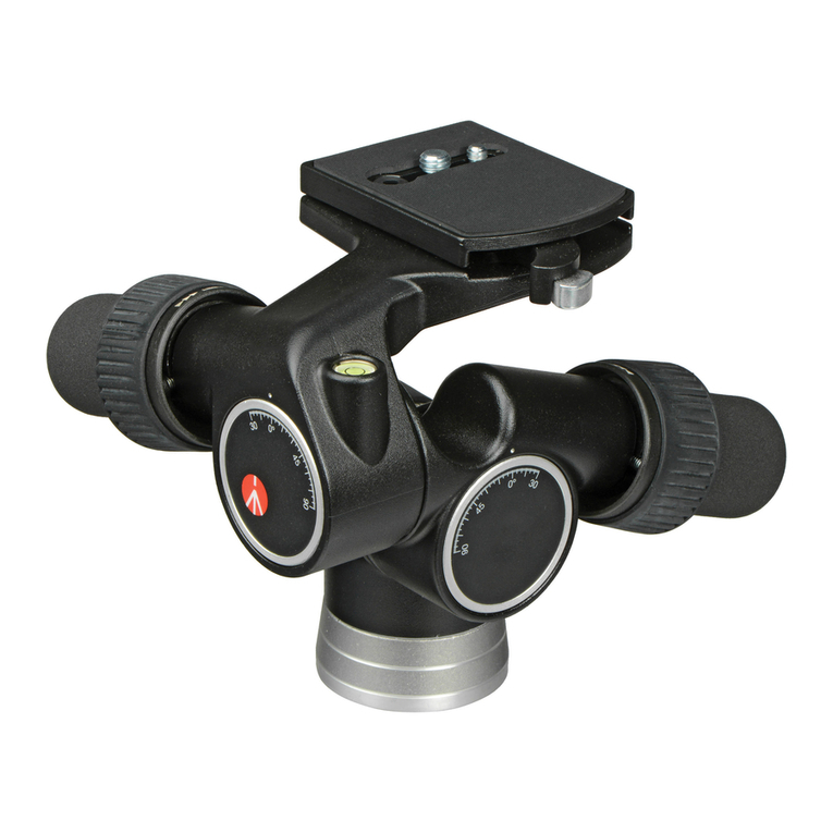
La testa 501HDV è fornita completa
di leva di comando telescopica “A”
non inserita. È possibile inserirla su
uno dei due lati della testa svitando
la manopola “D” e riavvitandola col
supporto “E” in corrispondenza del
foro “F”.
MONTAGGIO DELLA TESTA
SUL TREPPIEDE
Montare la testa sul treppiede tramite
il foro filettato da 3/8” “G”. I dischi
di fissaggio dei treppiedi Manfrotto
sono dotati di tre viti di bloccaggio
“H” per stringere la base della testa,
garantendo un assemblaggio solido
ed affidabile.
RIMOZIONE DELLA PIASTRA
RAPIDA DALLA TESTA
Per estrarre la piastra “L”, allentare
la leva di blocco “M” premendo
contemporaneamente il pulsante “N”
come mostrato in figura 2.
MONTAGGIO DELLA
VIDEOCAMERA
SULLA PIASTRA &
La testa (fig. 1) è fornita con viti da
1/4” “K” e da 3/8” “S” per il fissaggio
della videocamera alla piastra “L”.
Per rimuovere la vite inutilizzata
procedere come segue (fig. 2)
- premere dolcemente col dito sul
tappo in gomma “Q”
- rimuovere la vite che non serve
INTRODUCTION
Designed for digital ENG and DVD
camcorder and the use of telescopes
for loads up to 6kg.
KEY FEATURES
• Quick release sliding plate for
balancing the camcorder with
secondary safety latch
• 1/4”W and 3/8”W camera screw
and VHS pin
• 3/8” female tripod attachment
• Additional PAN and TILT friction
control
• Pan bar can be fitted left or right
• Spirit level for fine levelling
• Counter balance system for a load
of approx. 2,5kg/5.5 lbs
SET UP
The 501HDV head is supplied with the
telescopic pan bar “A” dismantled.
It can be mounted to the either side
of the head by unscrewing knob “D”
and screwing it with the casting “E”
on the hole “F”.
ASSEMBLING HEAD
ON TRIPOD
Assemble the head on the tripod
using 3/8” female thread “G”. The
top plate on Manfrotto tripods are
equipped with three set screws “H”
which clamp against the base of the
head to ensure effective and secure
locking.
REMOVE QUICK RELEASE PLATE
FROM HEAD
Extract plate “L” realising the locking
knob “M” whilst pushing button “N”
at the same time as shown in figure 2.
ASSEMBLING CAMCORDER ON
PLATE &
The head (fig. 1) is supplied with 1/4”
camera screw “K” and 3/8” camera
screw “S”on the plate “L”
To remove the screw not used
proceed as follow (fig. 2)
- lightly press the rubber cap “Q” with
your finger
- remove the screw not used
- reposition the cap to prevent the
screw from being lost
NOTE
The head is provided with threaded
housing for the screw not used (hole
for 3/8” screw “Z” and hole for 1/4”
screw “R” - fig. 1)
Fix the camcorder onto plate “L”
(fig. 3) by screwing camera 1/4”
screw “K” or 3/8” screw “S” into the
camcorder’s threaded hole WITHOUT
APPLYING FORCE (using for example
a coin).
If the camcorder has a hole for anti-
rotation, insert the pin “P” (fig. 2) on
the hole before screwing camera
screw.
Before fully locking, align the
camcorder lens with mark “LENS” on
the camera plate “L”.
MOUNTING THE CAMCORDER ON
THE HEAD &
Insert the camera plate “L” as shown
in figure 4 on top of the head until
locking button “N” clicks.
Hold the camcorder during the
follow operation to prevent it
from slipping backwards and
forwards.
Find the balance point for the
horizontally positioned camcorder:
• Level the head on the tripod (you
can use both tripods with flat
attachment or levelling bowl) using
the spirit level “J” (fig. 1)
• With the locking knob “U” (fig. 5)
unlocked and the friction control
“T” (fig. 7) at minimum, slide the
camcorder until find the equilibrium
point (fig. 5 and 6)
• Lock the plate “L” (fig. 7) in the
position reached by screwing the
locking knob “M”
REMOVE THE CAMCORDER
FROM THE HEAD
Whenever the camcorder needs to
be removed from the head, hold the
camera securely in one hand while
operating locking lever “M” and safety
button “N” with the other hand.
USE &
To use the head correctly, level the
head on the tripod (you can use
both tripods with flat attachment or
levelling bowl) using the spirit level
“J” (fig. 9)
The head features 360° pan and
vertical tilt (+90°/-60°) which are
controlled using the pan bar “A”
- The pan movement can be locked
using the knob “V” and it has an
UL
L
L
N
A
T
J
V
U
T
2
1
2
M
1
M
2
XB
ON
OFF B
5
7
9 10
8
6
1
1
1
2
2
2
2
3
3
1
1
4
4
5
5
6
6
7
7
8
8
9
9
10
10
INTRODUCTION
Rotule conçue pour des caméscopes
numériques ENG et DVD ou des
télescopes allant jusqu’à 6 kg.
CARACTÉRISTIQUES PRINCIPALES
• Plateau rapide coulissant doté d’un
levier de sécurité secondaire et
permettant d’équilibrer rapidement
le caméscope
• Vis de fixation 1/4” et 3/8” et ergot
VHS
• Filetage femelle pour trépied de
3/8”
• Molettes de réglage de la friction
des mouvements panoramique et
de bascule
• Levier panoramique pour droitiers
ou gauchers
• Niveau à bulle de précision
• Système de contre-balancement
pour une charge de 2,5 kg environ
PRÉPARATION
La rotule 501HDV est fournie avec le
levier panoramique télescopique “A”
démonté. Celui-ci peut être monté
du côté droit ou gauche de la rotule
en dévissant le bouton “D” et en le
revissant avec la fonderie “E” dans le
filetage “F” au centre de la rosace.
INSTALLATION DE LA ROTULE
SUR LE TRÉPIED
Fixez la rotule au trépied en insérant
la vis 3/8” du trépied dans l’orifice
fileté “G” de la rotule. Le socle de
la colonne centrale des trépieds
Manfrotto est équipé de trois vis “H”
qui, vissées à la base de la rotule,
permettent un verrouillage sûr et
efficace.
RETRAIT DU PLATEAU RAPIDE DE
LA ROTULE
Desserrez le bouton de blocage “M”
et appuyez sur le dispositif “N” pour
libérer le plateau rapide “L” (voir
figure 2).
FIXATION DU CAMÉSCOPE AU
PLATEAU RAPIDE ET
Le plateau rapide est équipé de deux
vis de fixation: “K” (¼”) et “S” (3/8”).
Procédez de la manière suivante pour
retirer la vis qui ne sera pas utilisée
(fig. 2):
- appuyez doucement sur le bouchon
en caoutchouc “Q” avec votre
doigt,
- retirez la vis dont vous n’avez pas
besoin,
- remettez le bouchon en caoutchouc
en place.
REMARQUE
La rotule est équipée de deux
compartiments filetés “Z” et “R”
permettant de ranger respectivement
la vis “S” et la vis “K” (fig. 1).
Fixez le caméscope au plateau “L”
(fig. 3) en vissant la vis “K” (1/4”) ou
“S” (3/8”) dans l’orifice fileté de la
base du caméscope SANS FORCER
(à l’aide d’une pièce de monnaie par
exemple).
Si le caméscope est doté d’un orifice
anti-rotation, insérez-y l’ergot “P” (fig.
2) avant de visser la vis de fixation.
Alignez l’objectif du caméscope avec
l’indication “LENS” du plateau rapide
“L” avant de verrouiller l’installation.
MISE EN PLACE DU CAMÉSCOPE
SUR LA ROTULE
ET
Faites coulisser le plateau rapide
“L” dans la rotule (voir figure 4)
jusqu’à entendre un “clic” indiquant
que le dispositif de blocage “N” est
correctement enclenché.
Tenez le caméscope pendant
cette opération afin de
l’empêcher de glisser vers
l’avant ou vers l’arrière.
Cherchez ensuite le point d’équilibre
qui permettra au caméscope d’être
bien horizontal, en procédant de la
manière suivante:
• Mettez à niveau la rotule sur le
trépied (il est possible d’utiliser un
trépied à socle plat ou équipé d’un
bol de mise à niveau) à l’aide du
niveau à bulle “J” (fig. 1).
• Déverrouillez ensuite le bouton “U”
(fig. 5), réglez la molette “T” de
réglage de la friction au minimum
et faites coulisser le caméscope
jusqu’à trouver le point d’équilibre
(fig. 5 et 6).
• Verrouillez enfin le plateau rapide
“L” (fig. 7) en serrant le bouton de
blocage “M”.
1
1
2
2 3
1 4 5 6 7
