manuals.online logo
Brands
  1. Home
  2. •
  3. Brands
  4. •
  5. Manhattan Comfort
  6. •
  7. Indoor Furnishing
  8. •
  9. Manhattan Comfort Astor 70.86 User manual

Manhattan Comfort Astor 70.86 User manual

Ed. 004, 2020/11 - Manhattan Comfort.
888-230-2225
help@manhattancomfort.com
Model # 222BMC1, 222BMC12, 222BMC2, 222BMC21,
222BMC6, 222BMC8, 222BMC9, 222BMC94
44
lb
11
lb
11
lb
11
lb
11
lb
Astor 70.86
Floating Panel / Panneau suspendu
The indicated values consider static weights and evenly distributed over the parts.
Les valeurs indiquées tiennent compte des poids statiques et uniformément répartis sur les pièces.
n.° ID
2
01
11
11
10
05
06
06
04
08
09
13
12
01
02
03
04
05
06
07
08
09
10
11
12
13
Panel / Panneau 1
2
2
1
1
2
1
1
1
1
2
2
1
03
02
03
02
07
For fixing
behind the panel.
Pour fixation
derrière les
panneaux.
For fixing
on the wall.
Pour fixation
au mur.
For fixing
behind the panel.
Pour fixation
derrière les
panneaux.
For fixing
behind the panel.
Pour fixation
derrière les
panneaux.
For fixing
on the wall.
Pour fixation
au mur.
For fixing
behind the panel.
Pour fixation
derrière les
panneaux.
REAR VIEW / VUE ARRIÈRE
INCLUDED IN THE PACKAGE / INCLUS DANS LE PACKAGE
Upper Rear Bar / Barre arrière supérieure
Lower Rear Bar / Barre arrière inférieure
Lower Support / Support inférieur
Base of the cubby / Base du compartiment
Side Panel of the cubby / Panneau latérau du compartiment
Partition of the cubby / Cloison du compartiment
Sliding Door / Porte coulissante
Middle Shelf / Étagère du milieu
Lower Shelf / Étagère inférieure
Handle 128mm / Poignée de porte 128mm
Plastic rail profile 1755mm / Profilé de rail en plastique 1755mm
Bar for wall / Barre pour mur
Parts Identification (Description) / Identification des pièces (Description) Quantity / Quantité
3
8x
A2x
B20x
C
20x
D14x
E6x
F
6x
G6x
H4x
I
1x
J4x
K
INCLUDED IN THE HARDWARE / INCLUS DANS LE MATÉRIEL
TOOLS NEEDED / OUTILS NÉCESSAIRES
Manual screwdriver.
Tournevis manuel.
Simple hammer.
Marteau simple.
Level indicator.
Indicateur de niveau.
Electric drill and electric
screwdriver with drill
bit Ø1/2 inch and
phillips tips.
Perceuse électrique
et tournevis électrique
avec foret Ø1/2 pouce
et pointes phillips.
!IMPORTANT! Two people are recommended to assemble and install this product.
IMPORTANT! Deux personnes sont recommandées pour assembler et installer ce produit.
4
• Line the floor with the foam mantle of the packing to protect the parts and arrange the Panel (01) with the
rear face upwards, correctly checking it the position according the holes and as shown in the drawing.
Tapisser le sol avec le carton et la feuille de mousse de l'emballage pour protéger les pièces et disposer le Panneau (01)
avec la face arrière vers le haut, en vérifiant correctement la position de chaque pièce selon les trous et le dessin.
• Place the Upper Rear Bars (02) and the Lower Rear Bars (03) behind the Panel (01) with dowels (A) and
glue according to the drawing, and fix them applying the indicated bolts (D) .
Placez les Barres arrière supérieures (02) et
les Barres arrière inférieures (03) derrière
le Panneau (01) avec des
chevilles (A) et de la
colle selon le dessin,
et fixez-les en
appliquant
les vis (D)
indiquées.
01
ATTENTION! APPLY GLUE.
ATTENTION! APPLIQUEZ DE LA COLLE.
03
03
• Finish the fixing of the Upper Rear Bars (02) in the Panel (01) applying
the two bolts (D) in the indicated positions.
Terminez la fixation des Barres arrière supérieures (02) dans
le Panneau (01) en appliquant les deux vis (D) indiquées.
• Fix the Lower Shelf (10) in the Panel (01) with
dowels (C) and bolts (E).
Fixez la Étagère inférieure (10)
dans le Panneau (01)
avec des chevilles (C)
et des vis (E).
• Insert the plastic
cover (J) into the
hole for pass wires
in the Panel (01).
Insérez le couvercle
en plastique (J) dans
le trou pour faire
passer les fils dans
le Panneau (01).
01
10
Preparing the parts (04), (05), (06) and (07):
• Fix the Lower Support (04) under the Base of the cubby (05) with dowels (C) and bolt (E).
• Fix the Side Panels (06) and the Partition (07) on the Base (05) with dowels (C) and
cam lock hardware (F + G). At the end of the fixing, apply the adhesive covers (H).
• Insert the plastic rail (12) into the channel in the Base (05).
Préparation des pièces
(04), (05), (06) et (07):
• Fixez le Support inférieur
(04) sous la Base (05)
avec les chevilles (C) et
la vis (E).
• Fixez les Panneaux
latéraux (06) et la
Cloison (07) à la Base
(05) avec les chevilles
(C) et le matériel de
verrouillage à came
(F + G). À la fin de la
fixation, appliquez les
couvercles adhésifs (H).
• Insérez le rail en
plastique (12) dans le
canal de la Base (05).
06
07
05
04
12
06
ATTENTION! APPLY GLUE.
ATTENTION! APPLIQUEZ DE LA COLLE.
LOWER EDGE / BORD INFÉRIEUR
02
Rear face
Face arrière
02
Front face
Face avant
STEP 1 / ÉTAPE 1
STEP 2 / ÉTAPE 2
STEP 3 / ÉTAPE 3
5
08
13
Preparing the Sliding Door (08):
• Apply the plastic guides (I).
• Choose the outer face of the Door (08) and
fix the handle (13) with bolts 3.5 x 25mm (D).
Préparation de la Porte coulissante (08):
• Appliquez les guides en plastique (I).
• Choisissez la face extérieure de Porte (08) et
fixez la poignée (13) avec des vis 3,5 x 25mm (D).
05
12
12
09
04
06
06
07
08
Installing the Sliding Door (08) and fixing the Middle Shelf (09):
• Insert the plastic rail (12) into the channel under the Middle Shelf (09).
• Insert the dowels (C) in the Side Panels (06) and in the Partition (07) and the bolts (F) in the Middle Shelf (09). After that, fit the parts together.
• Install the Sliding Door (08) by attaching the guides (I) in the rails (12) in the Base (05) and in the Middle Shelf (09).
• Finish the fixing the Middle Shelf (09) to the Side Panels (06) and to the Partition (07) with dowels (C) and cam lock hardware (F + G), and finally apply
the adhesive covers (H).
Installation de la Porte coulissante (08) et fixation de la Étagère du milieu (09):
• Insérez le rail en plastique (12) dans le canal sous l'Étagère du milieu (09).
• Insérez les chevilles (C) dans les Panneaux latéraux (06) et dans le Cloison (07) et les vis (F) dans l'Étagère du milieu (09). Après cela, assemblez les pièces.
• Installez la Porte coulissante (08) en installant les guides (I) dans les rails en plastique (12) de la Base (05) et de l'Étagère du milieu (09).
• Terminez la fixation de l'Étagère du milieu (09) aux Panneaux latéraux (06) et à la Cloison (07) avec les chevilles (C) et le matériel de verrouillage à came
(F + G). Puis appliquez les couvercles adhésifs (H).
10 01
05
09
04
06 07 06
• Install the cubby [parts (04), (05), (06), (07), (08) and (09), assembled in the STEP 5], positioning it on the Lower Shelf (10) and fixing the Base (05)
and the Middle Shelf (09) on the Panel (01) with dowels (C) and bolts 5.0 x 50mm (E).
Installez le compartiment [pièces (04), (05), (06), (07), (08) et (09), assemblé à l'ÉTAPE 5], en le positionnant sur l'Étagère inférieure (10) et en fixant
la Base (05) et la Étagère du milieu (09) sur le Panneau (01) avec les chevilles (C) et les vis 5,0 x 50mm (E).
• Apply bolt 5.0 x 50mm (E) to fix the Lower Shelf (10) in the Lower Support (04) .
Appliquez la vis 5,0 x 50mm (E) pour fixer l'Étagère inférieure (10) dans le Support (04).
STEP 4 / ÉTAPE 4
STEP 5 / ÉTAPE 5
STEP 6 / ÉTAPE 6
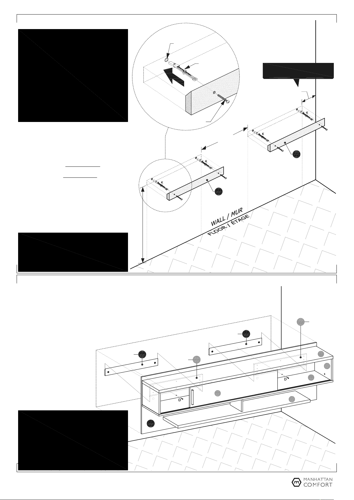
• Mark the position of the holes on the wall to fix the
Bars (11) as shown in the drawing and using the
bars themselves as reference.
Marquez la position des trous sur le mur pour fixer
les Barres (11), comme indiqué sur le dessin et en
utilisant les barres elles-mêmes comme référence.
• With electric drill and drill bit Ø1/2 inch, make the
holes in the wall.
Avec perceuse et un foret Ø1/2 pouce, faites les
trous dans le mur.
• Apply the bushings (K) into the holes in the wall
and fix the Bars (11) with the bevelled edge
facing up and to the wall, applying the bolts
1/4 x 2.1/4 inches, as indicated in the drawing.
Appliquez douilles (K) dans le trous du mur et fixez
les Barres (11) avec le bord biseauté vers le haut
et pour le mur, en appliquant les vis 1/4 x 2,1/4
pouces comme indiqué sur le dessin.
*The height 23.00 inches (584mm) indicated in the drawing,
between the floor and the lower edge of the Bars (11) is only
suggestive to install the Panel with its lower edge at
approximately 12.00 inches (305mm) from the floor.
La hauteur de 23,00 pouces (584mm) indiquée sur le dessin,
entre le étage et le bord inférieur des Barres (11) n'est
qu'indicative, pour installer le panneau avec son bord inférieur
à environ 12,00 pouces (305mm) du étage.
23.00 in (584mm)*
11
11
6
3.75 in
(95mm)
20.87 in
(530mm)
• With the Panel already assembled, fit Bars (02) fixed
behind the panel in the Bars (11) fixed on the wall.
Avec le Panneau déjà assemblé, monter les Barres
(02) fixée derrière le panneau dans les Barres (11)
fixée au mur.
• At the end of the installation, apply
the two security bolts (D) in the
indicated holes, to fix the Panel (01)
in the Bars (11) fixed on the wall
and prevent movement and
accidentally dropping the panel.
À la fin de l'installation, appliquez
les deux vis de sécurité (D) dans
les trous indiqués, pour fixer le
Panneau (01) dans les Barres (11)
sur le mur et éviter tout
mouvement et chute accidentelle
du panneau.
02
Fixed behind the panel.
Fixé derrière le panneau.
10
01
02
05
09
08
06
11
11
DETAIL 1
DÉTAIL 1
ATTENTION! Before installing the panel, check the
conditions of the wall for strength to properly support
and anchor the weight of the suspended furniture,
including the equipment and objects that may be fixed
to the panel.
The Kap Toggle bushings (K) supplied with the product are for
hollow walls or dry wall type. Check the type of wall on which
the installation will be made and, if necessary, look for more
suitable devices to fixation. To mark the position and fix the
Bars (11) on the wall, check the level of the parts.
ATTENTION! Avant d'installer le panneau, vérifiez les
conditions du mur pour la résistance nécessaire pour
supporter correctement le poids du meuble suspendu y
compris l'équipement et les objets qui peuvent être
fixés au penneau.
Les douilles Kap Toggle (K) fournies avec le produit sont
destinées aux murs creux ou à cloisons sèches.Vérifiez le type
de mur sur lequel l'installation sera effectuée et, si nécessaire,
prévoir des accessoires plus adaptés. Pour marquer la position
et fixer les Barres (11) au mur, vérifier le niveau des pièces.
Minimum fixing distance of the Bar (11) for
the panel installation close to walls corner.
Distance minimale de fixation de la Barre (11) pour
l'installation du panneau près du coin des mur.
Ø1/2 inch hole in the wall
Trou Ø1/2 pouce dans le mur
Kap Toggle bushing (K)
Douille Kap Toggle (K)
Bolt 1/4 x 2.1/4 inch
Vis 1/4 x 2,1/4 pouce
STEP 7 / ÉTAPE 7
STEP 8 / ÉTAPE 8
Fixed behind the panel.
Fixé derrière le panneau.
Fixed on the wall.
Fixé au mur.
Fixed on the wall.
Fixé au mur.
IMPORTANT! To remove the panel from the wall, to unscrew the
security bolts (D) applied as in STEP 8 and moving it upwards
slightly so as to disengage the chamfered edges of the Bars (02)
and (11) fixed behind the panel and on the wall. Before moving the
panel, remove TV and other objects that are installed or ensure that
the entire set is safe, preventing falls and damage to the panel and
equipment.
IMPORTANT! Pour retirer le panneau du mur, desserrer les vis de
sécurité (D) appliquées selon l'ÉTAPE 8 et la déplacer légèrement
vers le haut pour libérer les bords biseautés des Barres (02) et (11)
fixées derrière le panneau et sur le mur. Avant de déplacer le
panneau, retirez le TV et les autres éléments installés et
assurez-vous que l'ensemble est sécurisé, évitant les chutes et les
dommages au panneau et l'équipement.

This manual suits for next models

8

Other Manhattan Comfort Indoor Furnishing manuals

Manhattan Comfort Eldridge Wardrobe User manual

Manhattan Comfort

Manhattan Comfort Eldridge Wardrobe User manual

Manhattan Comfort GRANVILLE NS-500 User manual

Manhattan Comfort

Manhattan Comfort GRANVILLE NS-500 User manual

Manhattan Comfort FP1 User manual

Manhattan Comfort

Manhattan Comfort FP1 User manual

Manhattan Comfort Hampton User manual

Manhattan Comfort

Manhattan Comfort Hampton User manual

Manhattan Comfort Fortress 3GMCC User manual

Manhattan Comfort

Manhattan Comfort Fortress 3GMCC User manual

Manhattan Comfort CITY 1.2 User manual

Manhattan Comfort

Manhattan Comfort CITY 1.2 User manual

Manhattan Comfort Bradley User manual

Manhattan Comfort

Manhattan Comfort Bradley User manual

Manhattan Comfort UTOPIA 89300 User manual

Manhattan Comfort

Manhattan Comfort UTOPIA 89300 User manual

Manhattan Comfort 82300 User manual

Manhattan Comfort

Manhattan Comfort 82300 User manual

Manhattan Comfort Tribeca User manual

Manhattan Comfort

Manhattan Comfort Tribeca User manual

Manhattan Comfort 82300 User manual

Manhattan Comfort

Manhattan Comfort 82300 User manual

Manhattan Comfort Cabrini 23851 User manual

Manhattan Comfort

Manhattan Comfort Cabrini 23851 User manual

Manhattan Comfort Liberty 2.0 204AMC6 User manual

Manhattan Comfort

Manhattan Comfort Liberty 2.0 204AMC6 User manual

Manhattan Comfort 82200 User manual

Manhattan Comfort

Manhattan Comfort 82200 User manual

Manhattan Comfort Utopia 89900 User manual

Manhattan Comfort

Manhattan Comfort Utopia 89900 User manual

Manhattan Comfort Rockefeller Tall 5-Drawer Dresser User manual

Manhattan Comfort

Manhattan Comfort Rockefeller Tall 5-Drawer Dresser User manual

Manhattan Comfort Tribeca TV Panel User manual

Manhattan Comfort

Manhattan Comfort Tribeca TV Panel User manual

Manhattan Comfort Plaza 64.25 User manual

Manhattan Comfort

Manhattan Comfort Plaza 64.25 User manual

Manhattan Comfort Franklin FP3 User manual

Manhattan Comfort

Manhattan Comfort Franklin FP3 User manual

Manhattan Comfort 27900 User manual

Manhattan Comfort

Manhattan Comfort 27900 User manual

Manhattan Comfort Rockefeller User manual

Manhattan Comfort

Manhattan Comfort Rockefeller User manual

Manhattan Comfort CABRINI 1.2 User manual

Manhattan Comfort

Manhattan Comfort CABRINI 1.2 User manual

Manhattan Comfort BR 54 User manual

Manhattan Comfort

Manhattan Comfort BR 54 User manual

Manhattan Comfort Uptown 2.0 User manual

Manhattan Comfort

Manhattan Comfort Uptown 2.0 User manual

Popular Indoor Furnishing manuals by other brands

Regency LWMS3015 Assembly instructions

Regency

Regency LWMS3015 Assembly instructions

Furniture of America CM7751C Assembly instructions

Furniture of America

Furniture of America CM7751C Assembly instructions

Safavieh Furniture Estella CNS5731 manual

Safavieh Furniture

Safavieh Furniture Estella CNS5731 manual

PLACES OF STYLE Ovalfuss Assembly instruction

PLACES OF STYLE

PLACES OF STYLE Ovalfuss Assembly instruction

Trasman 1138 Bo1 Assembly manual

Trasman

Trasman 1138 Bo1 Assembly manual

Costway JV10856 manual

Costway

Costway JV10856 manual

moss DESIGN Caisson Credenza Assembly instructions

moss DESIGN

moss DESIGN Caisson Credenza Assembly instructions

Aquaglide FULL DECK 15.0 owner's manual

Aquaglide

Aquaglide FULL DECK 15.0 owner's manual

AREBOS AR-HE-SW30 user manual

AREBOS

AREBOS AR-HE-SW30 user manual

Till-Hilft Fulda 87005.330 Assembly instructions

Till-Hilft

Till-Hilft Fulda 87005.330 Assembly instructions

Twoey Outside 2010 quick start guide

Twoey Outside

Twoey Outside 2010 quick start guide

Hettich Easys 200 operating instructions

Hettich

Hettich Easys 200 operating instructions

The bedboss RELAX 404 Series owner's manual

The bedboss

The bedboss RELAX 404 Series owner's manual

Oeseder Möbelindustrie Bern 991 720 Assembly instructions

Oeseder Möbelindustrie

Oeseder Möbelindustrie Bern 991 720 Assembly instructions

Costway HW68469 user manual

Costway

Costway HW68469 user manual

Next ALIX A27743 Assembly instructions

Next

Next ALIX A27743 Assembly instructions

BROSA Hans Assembly guide

BROSA

BROSA Hans Assembly guide

Prodigg MINIKA PBA015T-FUR installation manual

Prodigg

Prodigg MINIKA PBA015T-FUR installation manual

manuals.online logo
manuals.online logoBrands
  • About & Mission
  • Contact us
  • Privacy Policy
  • Terms and Conditions

Copyright 2025 Manuals.Online. All Rights Reserved.