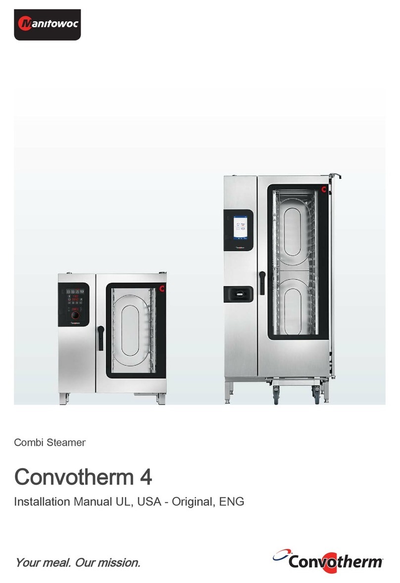
Manitowoc convotherm 4 User manual

Combi steamer Read instructions before use
Convotherm 4
Installation manual CE - Original, ENG
Your meal. Our mission.


Table of Contents
1 General information 6
1.1 Environmental protection 7
1.2 Identifying your combi steamer 8
1.3 Structure of customer documentation 10
1.4 Essential reading relating to safety 11
1.5 About this installation manual 12
2 Design and function 14
2.1 Design and function of the combi steamer 15
2.2 Layout and function of the operating panel 20
3 For your safety 21
3.1 Basic safety code 22
3.2 Intended use of your combi steamer 23
3.3 Warning signs on the combi steamer for table-top units 24
3.4 Warning signs on the combi steamer for floor-standing units 26
3.5 Hazards and safety precautions when moving the appliance 28
3.6 Hazards and safety precautions when setting up the appliance 29
3.7 Hazards and safety precautions during installing 30
3.8 Hazards and safety precautions when preparing appliance for use 32
3.9 Hazards and safety precautions when taking the appliance out of operation 35
3.10 Safety devices 38
3.11 Requirements to be met by personnel, working positions 41
3.12 Personal protective equipment 43
4 Moving the appliance 44
4.1 Working safely with the appliance 45
4.2 Moving the appliance to the installation location 46
5 Setting up the appliance 47
5.1 Safe working when setting up the appliance 48
5.2 Adjacent systems 49
5.3 Requirements for the installation location 50
5.4 Unpacking 55
5.5 Taking the appliance off the pallet 59
5.6 Setting up a table-top unit on a work surface 61
5.7 Setting up a table-top unit on a stand 63
5.8 Setting up a table-top unit on a wheeled stand 65
5.9 Setting up a floor-standing unit on the floor 68
6 Installation 69
6.1 Electrical installation 70
6.1.1 Safe working during electrical installation 71
6.1.2 Planning the electrical installation 72
6.1.3 Carrying out the electrical installation 74
6.1.4 Connection to an energy optimization system (electric appliances only) 75
6.2 Gas installation 77
6.2.1 Safe working when installing the gas 78
6.2.2 Planning the gas installation 79
6.2.3 Positions of the forced-air burners and gas distribution system 81
Table of Contents
Installation manual 3

6.2.4 Installing the gas 83
6.2.5 Measuring the supply flow pressure 84
6.2.6 Measuring the exhaust gas values 85
6.3 Water connection 86
6.3.1 Safe working when connecting the water supply and the drain 87
6.3.2 Water supply 88
6.3.3 Testing the water quality 92
6.3.4 Drain connection 93
6.4 Installing the fully automatic oven cleaning system 95
6.4.1 Safe working during the installation 96
6.4.2 Layout of the fully automatic oven cleaning system 97
6.4.3 Connecting the fully automatic oven cleaning system 98
7 Preparing the appliance for first-time use 100
7.1 Safe working when preparing the appliance for use 101
7.2 Procedure for preparing the appliance for first-time use 104
7.3 Measuring appliance gaps 106
8 Taking the appliance out of operation and disposal 107
8.1 Safe working when taking the appliance out of operation 108
8.2 Taking the appliance out of operation and disposal 110
9 Technical data 111
9.1 Dimensions and weights 112
9.2 Maximum permissible loading weight 115
9.3 Electrical supply 116
9.4 Gas supply 121
9.5 Gas consumption 122
9.6 Summary of gas data 123
9.7 Exhaust gas values 124
9.8 Exhaust gas output rate 125
9.9 Heat output 126
9.10 Heat output 127
9.11 Water connection 128
9.12 Boiler 129
9.13 Water quality 130
9.14 Water consumption, cooking 132
9.15 Water consumption, cooking and cleaning 133
10 Dimensional drawings and connection points 134
10.1 Connection diagrams for Convotherm 4 electrical appliances 135
10.1.1 Convotherm 4 6.10 electrical appliance 136
10.1.2 Convotherm 4 6.20 electrical appliance 138
10.1.3 Convotherm 4 10.10 electrical appliance 140
10.1.4 Convotherm 4 10.20 electrical appliance 142
10.1.5 Convotherm 4 12.20 electrical appliance 144
10.1.6 Convotherm 4 20.10 electrical appliance 146
10.1.7 Convotherm 4 20.20 electrical appliance 148
10.2 Connection diagrams for Convotherm 4 gas appliances 150
10.2.1 Convotherm 4 6.10 boiler gas appliance 151
10.2.2 Convotherm 4 6.10 injection gas appliance 153
10.2.3 Convotherm 4 6.20 boiler gas appliance 155
10.2.4 Convotherm 4 6.20 injection gas appliance 157
10.2.5 Convotherm 4 10.10 boiler gas appliance 159
Table of Contents
Installation manual 4

10.2.6 Convotherm 4 10.10 injection gas appliance 161
10.2.7 Convotherm 4 10.20 boiler gas appliance 163
10.2.8 Convotherm 4 10.20 injection gas appliance 165
10.2.9 Convotherm 4 12.20 boiler gas appliance 167
10.2.10 Convotherm 4 12.20 injection gas appliance 169
10.2.11 Convotherm 4 20.10 boiler gas appliance 171
10.2.12 Convotherm 4 20.10 injection gas appliance 173
10.2.13 Convotherm 4 20.20 boiler gas appliance 175
10.2.14 Convotherm 4 20.20 injection gas appliance 177
11 Checklists and completion of installation 179
11.1 Checklist: moving, setting up and installing the appliance 180
11.2 Checklist: Safety devices and warnings 181
11.3 Checklist: Customer guidance and instruction 182
11.4 Completion of the installation 183
Table of Contents
Installation manual 5

1 General information
Purpose of this chapter
This chapter shows you how to identify your combi steamer and provides guidance on using this man‐
ual.
Contents
This chapter contains the following topics:
Page
Environmental protection 7
Identifying your combi steamer 8
Structure of customer documentation 10
Essential reading relating to safety 11
About this installation manual 12
1 General information
Installation manual 6

1.1 Environmental protection
Statement of principles
Our customers' expectations, the legal regulations and standards and our company's own reputation
set the quality and service for all our products.
We have an environmental management policy that not only ensures compliance with all environmen‐
tal regulations and laws, but also commits us to continuous improvement of our green credentials.
We have developed a quality and environmental-management system in order to guarantee the con‐
tinued manufacture of high-quality products, and to be sure of meeting our environmental targets.
This system satisfies the requirements of ISO 9001:2008 and ISO 14001:2004.
Environmental protection procedures
We observe the following procedures:
Use of residue-free compostable wadding materials
Use of RoHS-compliant products
REACH chemical law
Recommendation and use of bio-degradable cleaning agents
Recycling of electronic waste
Environmentally friendly disposal of old appliances via the manufacturer
Join us in our commitment to protect the environment.
1 General information
Installation manual 7

1.2 Identifying your combi steamer
Position of type plate
The type plate is located on the left-hand side of the combi steamer.
Layout and structure of the type plate
Electrical unit Gas appliance Name
1Name of appliance
Combi Steamer
2Trade name
Element Meaning
C4 Convotherm 4 appli‐
ance series
eT easyTouch controls
eD easyDial controls
numbers
xx.yy
Appliance size
EB Electrical unit with
boiler
ES Electrical unit with wa‐
ter injection
GB Gas appliance with
boiler
GS Gas appliance with
water injection
3Part number
4Serial number
Element Meaning
Heating
method
Electric appliance
(X, V)
Gas appliance (Y,
W)
Steam gener‐
ation method
Injection (S)
Boiler (B)
Appliance
size
6.10 (1)
6.20 (2)
10.10 (3)
10.20 (4)
12.20 (5)
20.10 (6)
20.20 (7)
Year of man‐
ufacture
2014 (14)
2015 (15)
...
Month of
manufacture
January (01)
February (02)
March (03)
...
1 General information
Installation manual 8

Sequential
number
4 digits
5Gas data BTU/hr, gas type
1 General information
Installation manual 9

1.3 Structure of customer documentation
Contents of customer documentation
The customer documentation for the combi steamer includes the following documents:
Installation manual (this document)
User manual
easyTouch operating instructions (extract from the on-screen Help)
On-screen Help integrated in easyTouch (full instructions on how to use the software)
easyDial operating instructions
Topics in the installation manual
The installation manual is intended for trained professional staff; see '
Requirements to be met by per‐
sonnel
on page 41' in the installation manual.
It contains the following topics:
Design and function: describes the components relevant to installing the combi steamer
Safety: describes all the hazards and appropriate preventive measures relevant to installation tasks
Moving the appliance: contains necessary information on moving the combi steamer
Setting up the appliance: lists and describes the options for setting up the combi steamer
Installation: describes all the supply connections that are needed
Preparing the appliance for first-time use: describes how to prepare the combi steamer for use for
the first time
Taking the appliance out of operation: describes the tasks that need to be performed at the end of
the combi-steamer life cycle
Technical data, dimensional drawings and connection points: contains all the relevant technical da‐
ta for the combi steamer
Checklists: contains checklists for installing the combi steamer in compliance with the warranty
Topics in the user manual
The user manual is intended for trained staff and trained professional staff; see '
Requirements to be
met by personnel
' in the user manual.
It contains the following topics:
Design and function: describes the components relevant to operating the combi steamer
Safety: describes all the hazards and appropriate preventive measures relevant to operating the
combi steamer
Cooking: describes the rules, working procedures, operating steps and appliance usage instruc‐
tions for cooking
Cleaning: lists and describes cleaning processes, cleaning fluids, working procedures, operating
steps and appliance usage instructions for cleaning
Servicing: contains warranty information, the servicing schedule, information about faults, errors
and emergency use, plus working procedures, operating steps and appliance usage instructions
for servicing
Topics in the operating instructions and the on-screen help (easyTouch only)
The operating instructions and the on-screen help (easyTouch only) are intended for trained staff and
trained professional staff; see '
Requirements to be met by personnel
' in the user manual. For easy‐
Touch models, the operating instructions are an extract from the on-screen help.
The Operating instructions and online help (easyTouch only) include the following topics:
Layout of the user interface: explains the combi-steamer user interface
Using the software: contains instructions for entering and opening cooking profiles, for opening
cleaning profiles, for starting cooking and cleaning processes; describes how to make settings and
how to import and export data
Selected cooking profiles: lists tried and tested cooking profiles
1 General information
Installation manual 10
1.4 Essential reading relating to safety
Safety information in the customer documentation
Safety information relating to the combi steamer appears only in the installation manual and the user
manual.
The installation manual contains the safety information for the tasks covered by the manual and which
are performed when moving, setting up and installing the appliance and when preparing the appliance
for first-time use and taking the appliance out of operation.
The user manual contains the safety information for the tasks covered by the manual and which are
performed during cooking, cleaning and servicing work.
The safety information contained in the user manual and installation manual must always be consid‐
ered to be part of the operating instructions. The safety information contained in the user manual and
installation manual must always be observed when performing tasks that go beyond merely operating
the software.
Parts of this document that must be read without fail
If you do not follow the information in this document, you risk potentially fatal injury and property dam‐
age.
To guarantee safety, all people who work with the combi steamer must have read and understood the
following parts of this document before starting any work:
the chapter '
For your safety
on page 21'
the sections that describe the activity to be carried out
Danger symbol
Danger symbol Meaning
Warns of potential injuries. Heed all the warning notices that appear af‐
ter this symbol to avoid potential injuries or death.
Form of warning notices
The warning notices are categorized according to the following hazard levels:
Hazard level Consequences Likelihood
Death / serious injury (irreversible) Immediate risk
Death / serious injury (irreversible) Potential risk
Minor injury (reversible) Potential risk
NOTICE Damage to property Potential risk
1 General information
Installation manual 11

1.5 About this installation manual
Purpose
This installation manual is intended for all people who work with the combi steamer, and provides
them with the necessary information for proper and safe working when moving, setting up and instal‐
ling the appliance and when preparing it for first-time use.
Who should read the installation manual
Name of target group Tasks
Start-up engineer
(Service engineer)
Overall responsibility for preparing the combi steamer for first-time use
Instructing the user
Owner of the combi
steamer
or
Owner's member of staff
who is responsible for
the appliance
Made aware of all safety-related functions and devices of the combi
steamer by the start-up engineer.
Instructed by the start-up engineer on how to operate the appliance.
Provides assistance as instructed with conveying the appliance within
the establishment and setting up the appliance.
Equipment mover Conveying within the establishment
Service engineer Setting up the appliance
Installing the fully automatic oven cleaning system
ConvoClean / ConvoClean+ (optional)
Preparing the appliance for first-time use and taking the appliance out
of operation
Electrical fitter Connecting the appliance to the building's electrical supply
Disconnecting the electrical supply
Plumber Connecting the appliance to the building's water supply
Disconnecting the water supply
Connecting the appliance to the building's wastewater system
Disconnecting the wastewater system
Gas fitter Installing and removing the gas connection
Chapters in the installation manual
Chapter/section Purpose
General information Shows you how to identify your appliance
Provides guidance on using this installation manual
Design and function Specifies the intended use of the appliance
Explains the functions of the appliance and shows the position of its
components
For your safety Describes the hazards posed by the appliance and suitable preventive
measures
It is important that you read this chapter carefully.
Moving the appliance Specifies the basic appliance dimensions
Specifies the requirements for the installation location
Explains how to convey the appliance to the installation location
Setting up the appliance Explains how to unpack the appliance and specifies the parts sup‐
plied with the appliance
Explains how to set up the appliance
1 General information
Installation manual 12

Chapter/section Purpose
Installation Provides information on installing the:
Electrical supply
Gas
Water and waste water
Exhaust gas and vented air
ConvoClean+ / ConvoClean fully automatic oven cleaning system
Preparing the appliance for
use
Explains the procedure for preparing the appliance for first-time use
Taking the appliance out of
operation and
disposal
Explains the procedure for taking the appliance out of use
Contains information about disposal
Technical data Contains the technical data
Dimensional drawings and
connection diagrams
Contains the dimensional drawings and connection plans.
Checklists and completion
of installation
Contains the checklists for
Installation
Safety devices and warnings
Customer guidance and instruction
Contains information on the warranty and explains the completion
procedure using the checklists
Notation for decimal points
A decimal point is always used in order to achieve international standardization.
1 General information
Installation manual 13

2 Design and function
Purpose of this chapter
This chapter describes the design and construction of the combi steamer and explains its functions.
Contents
This chapter contains the following topics:
Page
Design and function of the combi steamer 15
Layout and function of the operating panel 20
2 Design and function
Installation manual 14

2.1 Design and function of the combi steamer
Components and function (electrical table-top units)
The following illustration shows a size 6.10 combi steamer as an example of all electric table-top mod‐
els:
Item Name Function
1Ventilation port External air intake for removing the moisture from the cooking
chamber
Smoothes out any pressure fluctuations in the cooking cham‐
ber
2Air vent Allows hot vapour to escape
3Door handle Opens and closes the appliance door
Venting position for opening the appliance safely (“safety
catch”)
Sure-shut function
Antibacterial material containing silver ions ("HygienicCare")
4Appliance door Closes the cooking chamber
Can slide back beside the appliance when opened in order to
save space (optional “disappearing door”)
5Operating panel Used for operating the appliance
Antibacterial ("HygienicCare")
6Suction panel Distributes the heat evenly inside the cooking chamber
7Rack Holds standard-sized food containers
8Core temperature probe,
sous-vide sensor (with ex‐
ternal socket)
Measures the core temperature of the food being cooked
9Cooking chamber Contains the food during cooking
10 Recoil hand shower Intended solely for rinsing out the cooking chamber with water
Retracts automatically into the holder after use
Antibacterial ("HygienicCare")
11 Appliance feet Can be adjusted in height to allow the appliance to be positioned
horizontally
12 Side panel Covers the appliance wiring compartment
13 Ventilation slots under‐
neath the appliance
Used for appliance ventilation
Must not be covered
14 Type plate Identifies the appliance
2 Design and function
Installation manual 15

Components and function (electric floor-standing appliances)
The figure below shows a size 20.20 combi steamer as an example of all electric floor-standing appli‐
ances:
Item Name Function
1Ventilation port External air intake for removing the moisture from the cooking
chamber
Smoothes out any pressure fluctuations in the cooking cham‐
ber
2Air vent Allows hot vapour to escape
3Door handle Opens and closes the appliance door
On-latch position for opening the appliance safely
Antibacterial material containing silver ions ("HygienicCare")
4Appliance door Closes the cooking chamber
Can slide back beside the appliance when opened in order to
save space (optional “disappearing door”)
5Operating panel Used for operating the appliance
Antibacterial ("HygienicCare")
6Suction panel Distributes the heat evenly inside the cooking chamber
7Core temperature probe,
sous-vide sensor (with ex‐
ternal socket)
Measures the core temperature of the food being cooked
8Built-in preheat bridge in
appliance door
Used for safety purposes during preheating and reduces energy
wastage
9Loading trolley Holds standard-sized food containers
10 Cooking chamber Contains the food during cooking
11 Recoil hand shower Intended solely for rinsing out the cooking chamber with water
Retracts automatically into the holder after use
Antibacterial ("HygienicCare")
2 Design and function
Installation manual 16

Item Name Function
12 Side panel Covers the appliance wiring compartment
13 Appliance feet Can be adjusted in height to allow the appliance to be positioned
horizontally
14 Ventilation slots under‐
neath the appliance
Used for appliance ventilation
Must not be covered
15 Type plate Identifies the appliance
Components and function (gas table-top units)
The following illustration shows a size 6.10 combi steamer as an example of all gas table-top models:
Item Name Function
1Ventilation port External air intake for removing the moisture from the cooking
chamber
Smoothes out any pressure fluctuations in the cooking cham‐
ber
2Exhaust outlet Takes away hot exhaust gases
3Air vent Allows hot vapour to escape
4Door handle Opens and closes the appliance door
Venting position for opening the appliance safely (“safety
catch”)
Sure-shut function
Antibacterial material containing silver ions ("HygienicCare")
5Appliance door Closes the cooking chamber
Can slide back beside the appliance when opened in order to
save space (optional “disappearing door”)
6Operating panel Used for operating the appliance
Antibacterial ("HygienicCare")
7Suction panel Distributes the heat evenly inside the cooking chamber
8Rack Holds standard-sized food containers
9Core temperature probe,
sous-vide sensor (with ex‐
ternal socket)
Measures the core temperature of the food being cooked
10 Cooking chamber Contains the food during cooking
2 Design and function
Installation manual 17

Item Name Function
11 Recoil hand shower Intended solely for rinsing out the cooking chamber with water
Retracts automatically into the holder after use
Antibacterial ("HygienicCare")
12 Appliance feet Can be adjusted in height to allow the appliance to be positioned
horizontally
13 Side panel Covers the appliance wiring compartment
14 Ventilation slots under‐
neath the appliance
Used for appliance ventilation
Must not be covered
15 Type plate Identifies the appliance
Components and function (gas floor-standing units)
The following illustration shows a size 20.20 combi steamer as an example of all gas floor-standing
models:
Item Name Function
1Ventilation port External air intake for removing the moisture from the cooking
chamber
Smoothes out any pressure fluctuations in the cooking cham‐
ber
2Exhaust outlet Takes away hot exhaust gases
3Air vent Allows hot vapour to escape
4Door handle Opens and closes the appliance door
On-latch position for opening the appliance safely
Antibacterial material containing silver ions ("HygienicCare")
5Appliance door Closes the cooking chamber
Can slide back beside the appliance when opened in order to
save space (optional “disappearing door”)
2 Design and function
Installation manual 18

Item Name Function
6Operating panel Used for operating the appliance
Antibacterial ("HygienicCare")
7Suction panel Distributes the heat evenly inside the cooking chamber
8Core temperature probe,
sous-vide sensor (with ex‐
ternal socket)
Measures the core temperature of the food being cooked
9Built-in preheat bridge in
appliance door
Used for safety purposes during preheating and reduces energy
wastage
10 Loading trolley Holds standard-sized food containers
11 Cooking chamber Contains the food during cooking
12 Recoil hand shower Intended solely for rinsing out the cooking chamber with water
Retracts automatically into the holder after use
Antibacterial ("HygienicCare")
13 Side panel Covers the appliance wiring compartment
14 Appliance feet Can be adjusted in height to allow the appliance to be positioned
horizontally
15 Ventilation slots under‐
neath the appliance
Used for appliance ventilation
Must not be covered
16 Type plate Identifies the appliance
Material
The interior and exterior structure of the appliance is made of stainless steel.
2 Design and function
Installation manual 19

2.2 Layout and function of the operating panel
Layout and elements of the easyTouch operating panel
Item Name Function
1ON/OFF
appliance
switch
Switches the combi steamer on and off
2Full
touchscreen
display
Central controls for appliance
Appliance operated by touching icons
on the control panel (full touchscreen
display)
Status displays
3USB port For connecting a USB stick
Layout and elements of the easyDial control panel
Item Name Function
1ON/OFF
appliance
switch
Switches the combi steamer on and off
2Control panel Central controls for appliance
Buttons for entering the cooking pro‐
grams
Displays showing the values you have
set
Prompts for the user
3USB port For connecting a USB stick
4C-Dial Combined rotary knob and pushbutton for
adjusting and setting the cooking parame‐
ters.
2 Design and function
Installation manual 20
Other manuals for convotherm 4
5
Table of contents
Other Manitowoc Kitchen Appliance manuals

Manitowoc
Manitowoc convotherm 4 User manual

Manitowoc
Manitowoc convotherm 4 User manual

Manitowoc
Manitowoc Convotherm 4 easyDial User manual

Manitowoc
Manitowoc convotherm 4 User manual

Manitowoc
Manitowoc Convotherm 4 easyTouch User manual

Manitowoc
Manitowoc convotherm 4 Operating instructions

Manitowoc
Manitowoc convotherm 4 User manual

Manitowoc
Manitowoc Servend 4 in 1 Tower Configuration guide