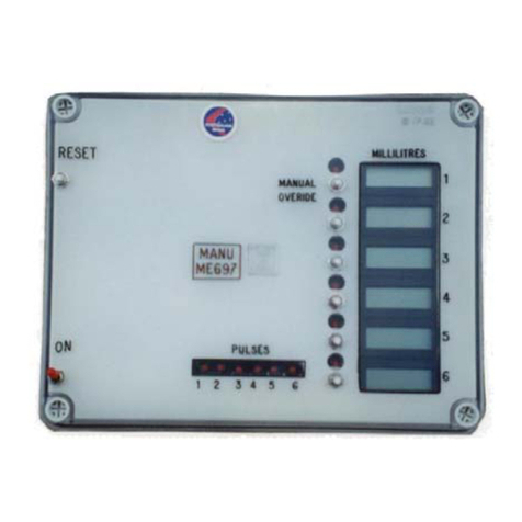
MANU ELECTRONICS ManuFlo ME995-7 User manual

ManuFlo
Flow Measurement & Control
Products
Rev: 04/20-AM
a division of MANU ELECTRONICS PTY LTD
41 Carter Road, Brookvale
Sydney NSW 2100 Australia
Ph: +61 2 9938 1425, 9905 4324
Fax: +61 2 9938 5852
Web: www.manuelectronics.com.au
Email: [email protected]
ME995-7 / RPFS-P WATER BATCHING SYSTEM
Congratulations on choosing a ManuFlo ® (Manu Electronics) preset batch control system.
You will now join over three thousand satisfied customers worldwide.
Your system comprises:
Information sheets included:
1. ME995 preset Batch Controller operation and specification.
2. Flowmeter operation, recommendations, and specification.
3. Plumbing installation guide.
4. Electricians wiring diagram.
5. Troubleshooting guide
Prior to installation:
A. Consider a good viewing and operating position for the ME995 Batch Controller.
B. Remove the detachable 10-pin plug from the rear of the ManuFlo controller. Wire the 240vac
supply. Wire the Active/contact drive, Neutral and Earth from the solenoid valve or return from the
external contactor if driving a pump. If starting a pump, make sure the contactor is of sufficient
amperage rating to handle the pump current draw. Consider wiring an override button (N.O. with
spring return) for manual batching or top up of water, which will be counted by the controller
display. See wiring diagram.
C. Install the Rota Pulse paddlewheel sensor (RPFS-P) in a straight pipe section, with the same
diameter pipe as the adaptor tee section, with 10x diameter before, and 5x diameter after, the
sensor with no elbows, reducers, valves or restrictions within this pipe run. Where the sensor is
housed, the pipe must be full when measuring.
D. The paddlewheel sensor comes with 5mtr cable. For extended lengths, use shielded cable only.
E. On pipe sizes over 50mm, consider using an air-assisted solenoid butterfly or angle seat valve, as
electrically-operated diaphragm valves can be very slow in closing (valves are available from
ManuFlo
®). Preferably, use a 240vac solenoid coil, as the Manu controller provides 240vac to
the coil when started. Otherwise, consult
ManuFlo
® for options.
F. The ME995 Batch Controller will be factory set to a nominal calibration number corresponding to
the pipe diameter selected. However, a calibration check must be performed on-site prior to
continuous use, and recalibration may be necessary (for details on calibration, see the
appropriate ME995 Data Sheet).
If unsure on any aspect of installation, call your local supplier or
ManuFlo
®.
Happy batching !!!!!!!!!!!!!!!

ManuFlo
Flow Measurement & Control Products
Page 1 a division of
MANU ELECTRONICS PTY LTD
www.manuelectronics.com.au
ME995-7
LITRES PRESET BATCH CONTROLLER
DATASHEET
FEATURES
4-Digit LED display.
4 LED status indicators.
Preact function.
Preset maximum limit.
Missing pulse detection.
Counts in Litres upto 9999.
Optional PLC and computer interface.
Signal conditioning, with K-factor.
Compatibility with most flowmeters.
The ME995-7 LITRES preset Batch Controller can be used with most pulse output flowmeters, for preset liquid batch
control applications.
The controller incorporates a preact (overflow deduct) feature, K-factor adjustment, 4 LED status indicators and
diagnostic safeties. With the ME995-7 Batch Controller using the same 10-pin Weidmuller receptacle plug as the previous
models, making changeover or upgrade instant with no rewiring necessary. It can be easily interfaced with PLCs, thus
incorporating the controller's safety features and providing a backup batch facility.
With 4 rotary selector switches, batch quantities are easily selected. The batch operator can also visually refer to the
numbered selector dials for the selected batch quantity. Command operations are by user-friendly toggle switches, and
four LEDs indicate operational status conditions.
Batch counting is in 1 Litre increments, up to a maximum 9000 Litres.
The controller operates from standard 220 - 260 vac (or optional 24vac, 110vac or 12 - 24 VDC) voltage supplies.
Contact output drive is via one (or optional two) relays. (or with –OC open contact drive to allow control output switching
drive of any external voltage). Standard controllers are in panel mount form, or optionally can be housed in a metal box or
IP65 ABS wall mount enclosure.
The ME995-7 controller is designed for compatibility with ManuFlo flowmeters and many other types.
Calibration for the desired flowmeter is selectable via the rear dials.
SAFETY FEATURES
* LIMIT (LM) LED activates if batch cycle reaches locked internal limit or if circuit diagnostics detect internal chip
problem. There is subsequent automatic shutoff of voltage contact drive.
* PULSE FAIL (PF) LED activates if no pulses arrive within 1.5 seconds (variable) initial start time period, or if pulses are
interrupted during batch cycle and fall below (variable) pulse scanning time (typical 30Hz). There is subsequent
automatic shutoff of voltage contact drive output.
* FLOW (FL) LED monitors and indicates incoming pulses from field flowmeter, or if TEST is used.
* CONTACT DRIVE (CD) LED indicates voltage contact output drive when pump or solenoid are activated.
* Internal audible ALARM sounds momentarily upon completion of batch cycle, and continuously if PULSE FAIL or LIMIT
LEDs are activated or if overflow runs 26 litres over selected batch quantity.
OPERATING INSTRUCTIONS ME995-7

ManuFlo
Flow Measurement & Control Products
Page 1 a division of
MANU ELECTRONICS PTY LTD
www.manuelectronics.com.au
* To operate, push each of the toggle switches ON-OFF, START-STOP and TEST-RESET to the desired function.
* Switch the power ON to unit. Select required batch quantity using rotary number dial selector switches.
* RESET unit. The LED displays zero and all LED indicators and alarm turns off. The unit is ready for batching.
* START unit; voltage contact drive activates. CONTACT DRIVE LED illuminates indicating pump or solenoid are energized,
followed by FLOW LED illuminating, indicating pulsing and operation of flowmeter. The digits begin counting upward towards the
selected batch quantity.
* Upon digits reaching the selected batch quantity the alarm sounds (short beep) indicating completion of batch; CONTACT DRIVE
and FLOW LEDs turn off. LED display digits and selected batch quantity should correspond. If LED digits overshoot target, use
PREACT (inflight,freefall) overflow deduct dials (located at rear of controller unit) to scale back the difference.
* To interrupt unit before completion of batch, push STOP toggle; digit counting will stop, drive contact off. Push START toggle to
resume batch.
* TEST toggle is used to test digit counting, switch contacts, alarm conditions or generate output pulses for computer interfacing.
TEST does not activate pump or solenoid.
Warning: if CONTACT or FLOW LED indicators are on, but controller is not counting, discontinue use and call for service.
CALIBRATION
1) The Batch Controller is initially set up for the connected flowmeter using
the Controller’s Calibration rotary selector knobs (at rear of unit) marked
UNITS, TENS and HUNDREDS to match flowmeter’s output pulse value.
Note reverse sequence of dials: e.g. U=0, T=0, H=3, is a value of 300.
On-site calibration adjustment and test:
2) Must adjust what is shown on the Batch Controller display (red LEDs) to
match a known amount dispensed, using the Calibration knobs. So, set
Controller to 190L, and batch into a 200 litre (44 gallon) drum.
3) If the amount collected is more than is shown on the LED display, then
decrease the set calibration value by the same % difference
e.g. if collected 200L when 190L on LEDs, this is 10L more or 5% over
(10/190x100%). So, decrease the calibration value by 5% i.e. if calibration set to
300, new value is 300-5% = 300-15 = 285 (Set Calibration U=5, T=8, H=2).
4) If the amount collected is less than is shown on the LED display, then
increase the set calibration value by the same % difference.
e.g. if collected 180L when 190L on LEDs, this is 10L less or 5% under
(10/190x100%). So, increase the calibration value by 5% i.e. if calibration set to
300, new value is 300+5% = 300+15 = 315 (Set Calibration U=5, T=1, H=3).
Example pulse flowmeter calibration settings
Note: x17 pulse input multiplier is used to enhance
calibration resolution if flowmeter has <58 pulses/Litre.
Flowmeter Size Ø H T U
Signal input
multiplier
RPFS 25mm 0 7 5 x1
PMS25 25mm 1 0 0 x 1
RPFS 32mm 7 8 2 x17
RPFS 40mm 5 1 0 x17
RPFS 50mm 3 4 0 x17
RPFS 80mm 1 2 4 x17
RPFS 100mm 0 7 8 x17
5) PREACT: Calibrating inflight overflow is via two rotary select knobs marked "TENS" and
“UNITS” of LITRES, located at the rear of controller. Simply set knobs to same overflow reading as
indicated by the LED display.
Example: You select 190 Litres, batch the quantity, 200 Litres is shown on display, and 200 Litres
is collected in drum. A valve may take extra time to close, so what is selected on dials usually
overshoots on display. So, set 10 Litres on PREACT to deduct the 10 Litres overshoot (PREACT
T=1, U=0 is a value of 10 Litres). Next batch, the selector Dials, LED reading and amount collected
in drum are all 190 Litres.
SPECIFICATIONS ME995-7
Power supply 220-260vac (optional 24,110 vac or 12-24 VDC)
Output to flowmeter 12 VDC upto 100mA
Relay outputs Standard Max. 240 vac, 1 A.
(Other outputs as per spec. option ordered)
Frequency input 5 KHz: x1 input, 340 Hz: x17 input. (min.10hz)
Display 4 digits, 7 segment LED (14mm H)
Connection 10 pin Weidmuller mating plug & socket
Fuse 1 Amp (5 x 20mm case)
Batch selection Visual rotary select knob switches
Batch commands Push toggle switches
Mounting Panel mount
Weather Rating Indoor only IP51 (for outdoor use HB2510 box)
Instrument housing ABS hi-impact case mould
External dimensions 206 L, 130 H, 90 D mm
Panel cutout 190 L, 122 H mm
Weight 1 kg
Due to continuous product improvement, specifications are subject to change without notice.
ORDERING CODES ME995-7
ME995-7 Batch Controller, 240 vac supply and output, with 12 VDC power to flowmeter (standard).

ManuFlo
Flow Measurement & Control Products
Page 1 a division of
MANU ELECTRONICS PTY LTD
www.manuelectronics.com.au
Options:
Code Description Code Description
-DC-OC 12-24 VDC power supply input/output
drive, with Open Contact output drive
(5 A) which is via external voltages
-5P 5-pin computer interface plug (start, stop, reset,
pulse,+12V) for use with ME5IC interface card for
Jonel, COMMANDbatch etc PLCs.
-24VAC 24 vac powered and output. -MC 4-pin PLC/Computer Command (Start/Stop/Reset)
interface plug.
-110 110 vac powered and output. -MC2 2-pin plug for scaled 4N33 open collector
pulse output (1 pulse/ 1 Litre).
Includes 4-pin external command
(Start/Stop/Reset) interface plug.
-OC Open Contact pump/valve output,
for use with any driving voltage
(maximum 5A current).
-SSRBC External command: Start/Stop/Reset,
for connection to HB2500-SSR housing box,
or for remote control facility.
-A0 Contact output: alarm/batch-complete
voltage relay or logic state
-S12 switch: two product changeover output drive.
Allows 2 flowmeter-inputs/pump-drives.
e.g. “ME995-7” is the standard Batch Controller, 240vac powered, whereas “ME995-7-MC2” is an ME995-7 Batch
Controller with a scaled open collector pulse output and a Start/Stop/Reset PLC commands interface.
HOUSING ENCLOSURES
SHB
SHB1
Single enclosure. Powder coated metal.
Single enclosure. Powder coated metal.
Wired with 240vac contactor (for 1 hp pump),
plug-in 240 vac pump outlet and plug.
SHB
SHB1
SHB1-T as for SHB1 above, but with terminal wiring entry
connection instead of 240vac pump outlet
DHB
DHB2
Dual enclosure. Powder coated metal.
Dual enclosure. Powder coated metal.
Wired with 2x 240vac contactors,
2x pump outlets, and
2x plugs for Batch Controllers.
DHB
DHB2
DHB2-T as for DHB2, but with terminal wiring entry connections
(instead of mains lead and pump outlets).
HB2510
-SSR
IP65 waterproof single enclosure.
External commands: Start/Stop/Reset.
IP65 rated (option fitted to HB2510).
HB2510-SSR IP65
enclosure
shown with
ME3000 Batch Controller
-MC2
I/O PLC/Computer
controlled Interface
option. Incorporates
the safety features
of ME995 and
provides operator
backup batch facility.

ManuFlo
Page 5 MANU ELECTRONICS PTY LTD
Flow Measurement Products 41 Carter Road, Brookvale NSW 2100
Website: http://www.manuelectronics.com.au
RPFS_Datasheet 23/02/2018
ADMIX
STORAGE
TANK
Filter
Non-Return
Valve
tank
Valve
outlet line
above level of
Storage Tank
(most common)
Gate Valve
restricts flow
Flowmeter Non-Return Valve
optional 3-W ay Valve
(calibration point)
optional 240vac Solenoid to
prevent Venturi effect when
injecting into water lines.
VAC
SUPPLY
E N A
A
N
TWIN
SHIELDED
CABLE
at rear of
Batch
Controller
PUMP
ME995
WIRING
DIAGRAM
ACTIVE
Optional batch override/top-up
momentary push button switch
Standard AC Wiring for Pump and optional Solenoid
atrearof
Batch
Controller
ACTIVE Rear
ME995
SHIELD(0v)
PULSE
SHIELDED
CABLE
CONTACT
CONTACT1
+VDC
Optionalbatchoverride/top‐up
momentarypushbuttonswitch
GateValve Solenoid
Flowmeter
‐‐ +
+VDC
0v
OpenContact
OutputDrive
12– 24
VDCsupply
0v
+VDC
EARTH
(GROUND)
liquid
+12VDC
0v +
PUMP
Wiring for DC-powered Batch Controller with DC Open Contact Output Drive to Pump and/or Solenoid
NOTE: if current draw of solenoid is > 0.5 Amps, or if using a pump, then install a contactor
ME995-7

ManuFlo
Page 6 MANU ELECTRONICS PTY LTD
Flow Measurement Products 41 Carter Road, Brookvale NSW 2100
Website: http://www.manuelectronics.com.au
RPFS_Datasheet 23/02/2018
RPFS
ROTA PULSE FLOW SENSOR
(Slip Insertion Paddlewheel) DATASHEET
FEATURES
± 2.5% accuracy @ velocity range 0.5 to 8.5 m/sec.
± 1 % accuracy over linear range 0.7 to 7.0 m/sec.
Repeatability of ±0.6%.
NPN inductive pulse with internal amplification.
Square wave output with short circuit protection.
Inductive coil pulse option for low current applications.
High Pressure options to 2000kpa
50C or 120C temperature models.
Simple installation and maintenance.
Large range of pipe adapter fittings in sizes 20 to 110mm.
(Larger pipe sizes to 500mm using “Long Stem” –LS version)
Stainless Steel 17-4PH paddlewheel rotor without magnets.
Australian made since 1984. (Now with new high speed bush option).
DESCRIPTION
The Rota Pulse Flow Sensor (RPFS) paddlewheel insertion type flowmeter uses a proven
principle of flow measurement, which is used worldwide. The RPFS comes in four model
variants:
RPFS-P for liquids up to 50C (plug-in cable)
RPFS-H for liquids up to 120C
RPFS-P
All model variants insert directly into a large range of pipe adapter fittings available in PVC, Galvanized Iron, Brass, Stainless
Steel or Polypipe materials, covering pipe sizes 20 to 110mm (standard sizes). This makes the RPFS suitable for a wide range of
liquid flow measurement, monitoring and batching applications. Using the BSPB & BSPSS fittings adaption to larger size pipes is
possible depending on pipe wall thickness, alternatively the Long Stem (-LS) versions with adaptors are then used.
With only one moving part and limited intrusion into the pipe, and combined with its flow-through design, the RPFS allows
accurate measurement of liquid flows with virtually no head losses.
Each of the 4 blades of the rotor (paddlewheel) extends approximately one centimetre into the flowing liquid. The RPFS-P sensor
generates a square wave pulse with the frequency output proportional to flow velocity and proportional to pipe diameter. The
RPFS-P incorporates internal amplification, allowing pulse transmission up to 1000 metres to the receiver device. The RPFS-P
model is specially constructed with a metal shielding jacket making it immune to electrical interference.
Magnets are not used in the RPFS models, thereby eliminating iron particles jamming the rotor. The alloy rotor used also makes
the RPFS less susceptible to interference from turbulence and particles hitting the rotor, thereby giving superior flow results.
SPECIFICATIONS
Model
RPFS-P RPFS-H
Supply voltage 5-30VDC 5-30VDC
Output signal NPN open collector NPN open collector
50% duty cycle pulse 50% duty cycle pulse
Current draw @ 5VDC / 24VDC 2.5mA / 10mA 2.5mA / 10mA
Max. switching current 200 Ma (at 24VDC) 200 mA (at 24VDC)
Cable length 5 metres, plug-in cable 2 metres cable
3-core (3 wire) 2-core shielded (3 wire)
Fluid temperature 50 °C max. 120 °C max.
Weather rating IP67 IP65
Pressure rating 200psi 400psi
Accuracy ± 2.5% for 0.5 to 8.5 m/s, ±1% for 0.7 to 7.0 m/s, Repeatability ± 0.6%
For Pipe Sizes 15 to 110mm standard,
Larger pipes via BSPB-LS special adaptor or saddle clamps.

ManuFlo
Page 7 MANU ELECTRONICS PTY LTD
Flow Measurement Products 41 Carter Road, Brookvale NSW 2100
Website: http://www.manuelectronics.com.au
RPFS_Datasheet 07/07/2018
SENSOR CONSTRUCTION RPFS
Model RPFS-P RPFS-H
Body Delron (Acetal) Brass
O-rings x 2 Neoprene Viton
Rotor Stainless Steel 17-4PH
Bushes Delron
Axle Tungsten Carbide
Lockcap PVDF Brass
Dimensions
Overall (approx.)
130L x 30W mm 150L x 30W mm
ORDERING CODES:-
NOTE: All RPFS sensors are supplied with a screw-down LC locking cap
Item Description
RPFS-P NPN transistor 5-25VDC sinking pulse,
liquid temperature to 50C
RPFS-H NPN transistor 5-25VDC sinking pulse,
liquid temperature to 120C
SPARE PARTS
PW-N Spare wheel
PWAH Axle
PC5 5 mtr m12 lead
LC Locking Cap
BS020 Orings
MAINTENANCE RPFS
Recommended Periodic Checks:
With clean liquids, sensor check of the paddle wheel is recommended once every year. In applications with reclaimed or
contaminated fluids, regular quarterly maintenance checks are recommended.
Removal of RPFS from Pipe adaptor Fitting ‘Square’ Keyway Type Nipple Adaptor:(see FIG 5)
1 - Unscrew the black PVC locking cap (anti-clockwise).
2 - Place a small to medium sized flat thin bladed screwdriver in the join where the insertion sensor body meets the nipple
adaptor (See FIG 4), twist the screw driver to prize the two apart till the slots clear the keyways, then pull or twist upwards
until the sensor is released (never pull via the cable).
Removal of RPFS from Pipe adaptor Fitting ‘Triangular’ Keyway Type Nipple Adaptor:(see FIG 6)
1 - Unscrew the black PVC locking cap (anti-clockwise).
2 - Hold the neck of the Tee piece in your left hand, grasp the RPFS body with your right hand and turn slowly anti-clockwise until
the sensor hydraulically raises out of slot then pull upwards out of the socket (never by the cable).
**When returning the sensor to nipple adaptor insert so the keyway and slots line up then then push down until they locate. Screw
the black locking cap clockwise to hold the sensor in place (hand tightened only).
Cleaning:
1 - If the paddlewheel (rotor) and or sensor body is coated with scale, immerse the sensor section in diluted hydrochloric acid, scour
gently if required.
2 - For ease of removal or refitting of sensor we strongly recommend to lubricate the body O-rings using petroleum jelly.
3 - If the paddlewheel requires servicing, push out the axle using a small hole punch or similar implement, remove the
paddle wheel and service or replace rotor and/or axle as required (spare parts available from ManuFlo).
Fault Diagnosis & Rectification:
If the RPFS sensor ceases to count, the paddlewheel may be blocked, remove inspect and clean as described above.
If the RPFS pulses when there is no flow, a nearby 50Hz AC field is probably causing these false counts. Move the flow sensor
away from the 50Hz field, or move the source of the field if practical.
If the standard cable length supplied is not sufficient and needs extending contact ManuFlo for suitable ‘screened’ cable and never
run extended cable across or near to other cables that are potential EMF sources.

ManuFlo
Page 8 MANU ELECTRONICS PTY LTD
Flow Measurement Products 41 Carter Road, Brookvale NSW 2100
Website: http://www.manuelectronics.com.au
RPFS_Datasheet 07/07/2018
INSTALLATION GUIDE RPFS
Adapter Tee keyway fittings are available in:
1. PVC Class 18 Cat. 19 Slip tees (F-glue-ends) pressure pipe
Sizes: 20, 25, 32, 40, 50, 65, 80 & 100 mm.
PVC high pressure saddle clamps: 40, 50, 80 and 100mm.
2. Galvanized Iron threaded connections:
BSP (F): pipe sizes 25, 32, 40 & 50 mm;
BSP (M) pipe sizes 80 & 100mm.
3. Gunmetal BSP(m) threaded connection end pipe tube tees 20 mm.
4. Polypipe saddle clamps in pipe sizes 40, 50, 63, 75, 90, 110 mm
5. PVC saddles 40, 50, 80 and 100mm.
6. Stainless steel 25, 32, 40 & 50mm, larger sizes fabricated on request.
7. FOR PIPE SIZES 110mm and larger refer to the RPFS-LS model
**Further custom made fittings are available on request.
Use ManuFlo BSPB, BSPB-LS (Long Stem) Brass or BSPSS Stainless Steel
pipe adapter keyway nipple - with locknut, which has a 1” OD BSP thread for
screwed insertion into 1”(female BSP) half-sockets which can be welded
directly to pipe, the BSPB fittings can be coupled to any 1” BSP female entries
including saddle clamps.
Installation Conditions
IMPORTANT: A minimum of 10x pipe diameter before (upstream of) the
sensor and at least 5x pipe diameter after sensor of straight pipe section
must be fitted, with no bends, reductions, enlargements, restrictions, valves
etc within this section. This will help eliminate flow turbulence to ensure
optimum accuracy performance.
The RPFS sensor must measure in a full pipe flow section.
Can be installed in a horizontal, inclined or vertical pipe position.
(Note: If mounted in horizontal or inclined pipe, make sure
insertion position of sensor is at top or 45 from top, not on the underside).
Selection of pipe diameter:
(For best results, use the table below):
Pipe size Flowrange (Litres/min) Pulses/Litre
(mm) Min Max (approx.)
(1)(2)
20 13 160 116
25 20 250 75
32 30 410 46
40 50 640 30
50 90 1000 20
63 132 1580 11.7
65 120 1690 12
75 180 2250 8.3
80 190 2560 7.3
90 244 3240 5.7
100 300 4005 4.6
110 (-LS) 343 4845 3.8
125 (-LS) 426 6255 3.0
140 (-LS) 516 7850 2.4
150 (-LS) 600 9010 2
160 (-LS) 650 10200 1.8
195 (-LS) 900 15200 1.22
200 (-LS) 950 16000 1.16
250 (-LS) 1480 25000 0.7
280 (-LS) 1850 31400 0.6
ELECTRICAL INSTALLATION/DATA Cable connection:
RPFS-P# Black = Pulse
Brown = + 5-30 VDC
Blue = O.V. ground/shield
looking at
plug on
RPFS-P sensor
Brown
(5-30 VDC)
Black
(Pulse)
Blue
(Ground)
looking at
socket on
RPFS-P cable
Brown
(5-30 VDC)
Black
(Pulse)
RPFS-H# White = Pulse
Red = + 5-30 VDC
Shield = O.V. ground/shield
# If connecting to non-ManuFlo equipment, a 2K2 pull-up resistor
may be required between (+) and Pulse.
For extra cable length, use shielded cable only!
WARNING: To avoid electrical interference the RPFS-H and RPFS-L
should not be installed within 30cm of any AC fields, otherwise 50Hz
could be detected and create oscillations.
(1) For >315mm diameter pipes:
Pulses per Litre = 50273 / [ (Pipe diameter in mm) 2.016 ]
(2) NOTE: Due to gravitational forces, the pulse output value can differ
up to 6% between a vertical flow that is upwards or downwards. Where
possible, perform a calbration check to determine pulse rate given the
pipe diameter and flow conditions. Once calibrated, meter will give linear
and repeatable results within the flow range
Installin
g
Into Existin
g
Pi
p
e Lines
FI
G
.1
IMPORTANT:

ORDER CODES FOR PIPE ADAPTOR FITTINGS RPFS
Material GAL PVC PVC Polypropylene Polypropylene STAINLESS BRASS BRASS
Type T-Piece slip T-piece Saddle Clamp Saddle Clamp Saddle Clamp T-Piece T-piece Socket
For Gal pipe Pressure pipe Pressure pipe Pressure pipe Poly Pipe Black S/Steel pipe Brass pipe
20 mm PVC20 BRA20
25 mm GAL25 ( -T2) PVC25 SS25 BRA25
32 mm GAL32 PVC32 SS32 BSOC:
1” BSP
Brass
pipe socket
adaptor
for
25-100mm
pipes
also
BSPB &
BSPSS
nipple
adaptor
40 mm GAL40 PVC40 PVC40SC SCP40 SC40 SS40
50 mm GAL50 PVC50 PVC50SC SCP50 SC50 SS50
63 mm SCPE63 SC63
65 mm PVC65 SCP65 SC75
75 mm SC75
80 mm GAL80 PVC80 PVC80SC SCP80 SC90
80 mm GAL80-F
(Table D flanged)
90 mm SCPE90 SC90
100 mm GAL100 PVC100 PVC100SC SCP100 SC114
100 mm GAL100-F
(Table D flanged)
110 mm SCPE110 SC110
BSOC:
1” BSP
Brass
pipe socket
adaptor
for
100-500
mm pipes
also
BSPB-LS
Long Stem
nipple
adaptor
125 mm SCPE125-LS SC125-LS
140 mm SC140-LS
150 mm PVC150SC-LS SCP150-LS SC160-LS
160 mm SCPE160-LS SC160-LS
200 mm PVC200SC-LS SCP200-LS SC200-LS
225 mm SCPE225-LS SC225-LS
250 mm SCP250-LS SC250-LS
280 mm SC280-LS
300 mm PVC300SC-LS SCPE300-LS SC315-LS
315 mm SC315-LS
500 mm
Galvanised iron
threaded ends
BSP (female)
2000 kPa
Note: 25mm
can be supplied
with straight
pipe sections
already fitted
(Part GAL25-T2)
PVC
T-piece
Class 18 Cat 19
Glue-in (female)
1100 kPa
PVC
1400 kPa
PVC
≤ 150mm:
1600 kPa
> 150mm:
1000 kPa
Poly-pipe
agricultural
Saddle Clamps
≤ 150mm:
1600 kPa
> 150mm:
1000 kPa
Stainless
Steel 316
T-piece.
BSP
(female)
threaded
entry
2000 kPa
Brass
T-piece
BSP
(female)
threaded
entry
2000 kPa
1” BSP
Brass
pipe
socket
adaptor
& BSPB
BSPB-LS
BSPSS
nipple
adaptors
(see Fig 1
Page 3)
GAL80 - 80mm Galvanized Iron pipe adapter
(80mm ɸ x 600mm long)
BSPSS Stainless Steel
adapter nipple
for 25-100mm pipes
BSPB brass
adapter nipple
for 25-100mm pipes
Due to continuous product improvement, specifications are subject to change without notice.
** Pipe fitting options for the RPFS are as per the table however other fitting types may also be available on request**

RPFS and ME995 Wiring and Plumbing Diagrams
(c) 2004 Manu Electronics Pty Ltd 1

RPFS and ME995 Wiring and Plumbing Diagrams
(c) 2004 Manu Electronics Pty Ltd 2

RPFS and ME995 Wiring and Plumbing Diagrams
(c) 2004 Manu Electronics Pty Ltd 3

Page 1
TROUBLE SHOOTING GUIDE
ManuFlo
®
TM
FOR BATCH CONTROLLER / ROTA PULSE FLOW METER SYSTEMS
PROBLEM POSSIBLE CAUSE SUGGESTED SOLUTION
No power to batch controller Blown fuse or holder not tightened Check fuse, tighten fuse holder (at rear of controller)
or displays not on +12vdc and O.V. shorted Check pulse cable from DCD to RPFS meter
No main power supply Check power supply, check wiring
Pulse fails at start of batch •Check calibration (K-factor) setting •000 calibration -pulsefails. Make sure a calibration value is set,
(1.5 seconds after) three switch shafts -H,T,U- located at rear top left of controller
Seized paddlewheel Remove RPFS, inspect; if calcium buildup clean with diluted acid,
check axle/bushes, make sure paddlewheel spins freely.
Solenoid valve not opening Check and service solenoid valve, check output control voltage is
240vac(N & C, pins 7&9) when pushing start button. Or other
voltage as per specification output
Restriction or service gate valve closed Open gate valve
Empty water tank, Check water level
Pump not turning Check and service pump
•Pump foot valve failed •Empty pipe, Install non-return valve
Signal cable cut, bad joint at JB, Check signal cable for 12VDC at junction box near RPFS meter
oxidized cable- leakage If no power, cable cut or oxidized- repair/replace.
Unwire RPFS, take up to batchroom, remove extension cable &
hardwire RPFS direct into the Batch controller (P,+,-), spin wheel
should count on display, if so, then extension cable or connections
at JB faulty, if no counts & 12vdc present then RPFS faulty
•RPFS not positioned in pipe •Check RPFS slots are in keyway position, lock cap secured
Paddlewheel not inserted into flow stream
RPFS Flowmeter faulty Replace with new RPFS
Pulse fails during batch cycle Flowrate too slow Open restriction gate valve, or increase flowrate pulse fail
timing capacitor (see service guide). Pipe diameter too big for flow
Pipe buildup restricting flow Cleanout pipelines, calcium buildup on pipe walls -recycle systems
Paddlewheel problem Calcium buildup on wheel, soak in diluted acid. Warn bushes.
Display digits count slowly Non return valve faulty (jammed open) Clean, service or replace
after batch complete •Solenoid valve not properly closed •damaged seal, faulty solenoid
Batch target display counter Flowrate too fast excessive overflow Turn down gate valve to restrict flowrate
counts past batch selection or set pre-act (overflow deduct) function to compensate
Reduce delivery pipe diameter
•Intermittent overflow past batch select •Faulty solenoid valve not closing •service solenoid valve, check air pressure
or water does not stop properly, insufficient air pressure
Wet loads, more water Paddlewheel bushes worn Check paddlewheel
collected than indicated Wheel dirty, flowing over range Replace with new paddlewheel, recalibrate
Dry loads, less water Requires recalibration test Set new calibration figure, rear switches
collected than indicated (See calibration guide for details -ME995-7 brochure)
Controller starts counting Active and contact power Contactor fused due to excessive current draw from pump
when power switched on drive short circuited Relay fused due to excessive current draw on solenoid coil
- install higher current rated contactor or install contactor.
Controller- FL(flow), LM(limit), Controller malfunction, IC failure Replace controller or call for service and advise
and or CD(contact drive) LEDs on Diagnostic warning
Sequential fault finding and rectification
1. If another ManuFlo controller (any model) is available, simply unplug doubtful unit and plug in exchange unit. If the new unit is also not
operating correctly, then the problem is isolated to the pulse flowmeter or wiring.
2. When checking flowmeter, reset the ManuFlo controller. Remove the flow sensor and spin the paddlewheel. Check that the ManuFlo
controller has registered a number of counts on its display. If so, the electrical connections are probably OK. If no counts are registered,
check that 12VDC is supplied to the flow sensor. If supplied, then switch off the ManuFlo controller and replace the RPFS flow sensor.
3. The flow sensor paddlewheel is jammed, damaged etc. (For servicing, refer to the flow sensor brochure).
System over batch problem
1. Selector knob batch dials on ManuFlo Batch Controller may not be positioned correctly, and therefore not correspond to rotary switch
numeric values.
2. To test, set all numbered dials to the zero position 0000. Then press the RESET toggle. The alarm should beep momentarily - this will
indicate correct alignment of dials. If alarm does not beep, this indicates incorrect alignment of number dials. To rectify, remove the grey
colored cap from dial, unscrew knob and pull knob off. Check that the exposed switch shaft’s flat (black) side is horizontal. If not, then turn to
horizontal and refit the numbered dial knob to the zero number setting. Also check the calibration and pre-act knob settings which are located
at the rear of the controller
3. If the Batch Controller is found to be operating correctly, then proceed to checking and testing the flowmeter components.
If in further doubt, contact your local representative, or ManuFlo on ph +61 2 9938 1425 or 9905 4324.

page 2
SERVICE ADJUSTMENTS
to safety timings and limits for ME995 (ME188) preset batch controllers.
INITIAL START (T2): Once the START toggle is pressed, the controller allows a standard 1.5 seconds for pulses to arrive from the flowmeter. If
there are no pulses within the standard 1.5 second time period, the controller will shut down the output voltage drive, and turn on the Pulse Fail LED
and alarm warnings. In some applications, the 1.5 second delay may not be long enough, due to slow opening solenoids or slow pressure buildup
pumps etc. The initial start time period can be increased by soldering a tantalum capacitor in parallel with the standard capacitor value found on the
rear of the Printed Circuit Board (PCB). See Table 1 and diagram below, for values and location on the PCB.
FLOWRATE (T1): If pulses do arrive within the allocated initial start time, the controller then locks the pulse-rate safety. Most ManuFlo Batch
Controllers have a standard 30 counts per second (30Hz) pulse-rate safety setting. If the pulses from the flowmeter drop below 30Hz, the controller
will shut down the output voltage drive, and turn on the Pulse Fail LED and alarm warnings. The 30Hz standard setting is typical with water
dispensing systems using RPFS-P paddlewheel flowmeters, where if the flowrate drops below 30 counts per second the pulse fail safety will
activate e.g. 50mm pipe diameter section (20 pulses/Litre), 30 Hz =1.5 Litres/sec minimum flowrate required. If flow drops below 1.5 Litres/sec, the
pulse-fail will activate. The equation is:
Pulse-fail frequency (Hz) = (Pulses/Litre) x (minimum flowrate of pipe diameter in Litres/sec)
The flowrate (frequency Hz) minimum setting can be adjusted by soldering a capacitor in parallel with the standard capacitor found on the PCB.
See Table 2 and diagram below, for values and location on the PCB.
Note: The flowrate safety timing is changed if required by very low flowrate applications, or when using flowmeters other than the most commonly
used RPFS-P paddlewheel pulse output flowmeters. (low pulse-rate/litre flowmeters). When controller/flowmeter systems are ordered, we supply
the safety timing setting to suit your chosen flowmeter, thus always providing the safest possible watchdog system.
LIMIT (LM): The maximum permissible batch limit is determined by the factory-set internal limit value. The factory setting is always at the maximum
value. The limit setting can be reduced by simply de-soldering the limit lead wire (connected to the rear of rotary switch solder pads) and re-
soldering the wire to set the desired quantity (see diagram below).
Standard factory set values are T2: 1μF capacitor, T1: 0.02 μF capacitor.
Use the following tables to change factory set values.
Table 1. INITIAL START TIMING (T2) Table 2. FLOWRATE TIMING (T1)
Extra Capacitor value Extra timing Total Capacitor value Frequency Hz (pulses per second)
1 µF 1.5 seconds 0.01 µF 30 Hz (RPFS-P)
2 µF 3.0 seconds 0.02 µF 25 Hz
3.3 µF 4.1 seconds 0.03 µF 20 Hz (low flowrate MES20)
4.7 µF 5.8 seconds 0.1 µF 07 Hz
0.2 µF 03 Hz
1.0 µF 0.2 Hz (PSM20-T flowmeters)
This manual suits for next models
1
Table of contents
Other MANU ELECTRONICS Control System manuals
Popular Control System manuals by other brands

Fike
Fike FIK-PULL-SA Installation and maintenance instructions
Crestron
Crestron 3 Series Operation guide

Crestron
Crestron FT-TSC600 FlipTop Supplemental guide

Movcam
Movcam SCU-1 user guide
Mitsubishi Electric
Mitsubishi Electric AE-200A Instruction book
J.R. Clancy
J.R. Clancy SceneControl 100 operating instructions
