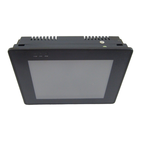
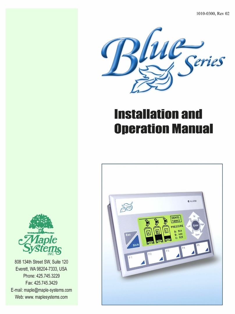
Maple Systems HMI5000 Series User manual

.Maple Systems Inc., 808 134th Street SW, Suite 120, Everett, WA 98204-7333 –www.maplesystems.com
1036-0175 Page 1 of 6 Rev. 01, 03/04/2011
C O N T R O L L E R I N F O R M A T I O N S H E E T
Maple Model(s)
PLC or Controller
HMI5000 Series
Allen-Bradley
PLC-5/xxE Series
(Ethernet)
Summary
Maple Systems’ HMI5000 Series Human/Machine Interface Terminals (Maple HMIs)
communicate with Allen Bradley PLC5e-series controllers using the DF1/PCCC protocol,
using the DF1 Typed Read and Typed Write commands. When configured with EZware-5000,
the Maple HMI is the master in a single master, multiple slave format. Please refer to the
HMI5000 Series Programming Manual for information on connecting multiple Maple HMIs to
a single PLC.
Compatible PLCs
PLC Family
PLC Model
PLC-5
PLC-5/20E, PLC-5/40E, PLC-5/80E;
1785-ENET/C Module
Communications
Cab
le
The Maple HMI should be connected to the ethernet port on the PLC or module. A list of
communications cables offered by Maple Systems as well as cable assembly instructions to
assist you in assembling your own communications cable are available on our website at
www.maplesystems.com.
WARNING If your communications cable is not wired exactly as shown in our cable
assembly instructions, damage to the HMI or loss of communications can
result.

Phone: 425/745-3229 • Fax: 425/745-3429 • Email: support@maplesystems.com • www.maplesystems.com
1036-0175 Page 2 of 6 Rev. 01, 03/04/2011
Accessible PLC Memory
Register
M
emory
The following table lists the PLC’s register memory ranges that the Maple HMIs are able to
access. Please note that your PLC’s memory range may be smaller or larger than that
supported by these HMIs. The following register memory can be displayed in 16 or 32-bit
format on the Maple HMI. (Note: d=decimal)
PLC Register Type
Address Range
Format
PLC Register Description
N7
0-999
ddd
Default Integer data file
F8
0-999
ddd
Default Floating Point data file
Nfn
0-254254
fffnnn
File No. fff: 7, 9-254
Element No. nnn: 0-254
Any Integer Data File
Ffn
0-254254
fffnnn
File No. fff: 8, 9-254
Element No. nnn: 0-254
Any Floating Point Data File
T4PRE
0-999
ddd
Default Timer File
Preset Value
T4ACC
0-999
ddd
Default Timer File
Accumulated Value
C5PRE
0-999
ddd
Default Counter File
Preset Value
C5ACC
0-999
ddd
Default Counter File
Accumulated Value
TfnPRE
0-254254
fffnnn
File No. fff: 4, 9-254
Element No. nnn: 0-254
Any Timer File
Preset Value
TfnACC
0-254254
fffnnn
File No. fff: 4, 9-254
Element No. nnn: 0-254
f
Any Timer File
Accumulated Value
CfnPRE
0-254254
fffnnn
File No. fff: 5, 9-254
Element No. nnn: 0-254
Any Counter File
Preset Value
CfnACC
0-254254
fffnnn
File No. fff: 5, 9-254
Element No. nnn: 0-254
Any Counter File
Accumulated Value
S
0-999
ddd
Status File

.Maple Systems Inc., 808 134th Street SW, Suite 120, Everett, WA 98204-7333 –www.maplesystems.com
1036-0175 Page 3 of 6 Rev. 01, 03/04/2011
Discrete Memo
ry
The following table lists the PLC’s discrete memory ranges that the Maple HMIs are able to
access. Please note that your PLC’s memory range may be smaller or larger than that
supported by these HMIs. The following discrete memory is displayable in single-bit format
on the Maple HMI. (Note: d=decimal)
PLC Bit Type
Address Range
Format
PLC Bit Description
B3
000-99915
dddbb: bb = bit number
w/ leading zero
Default Bit File
N7Bit
000-99915
dddbb: bb = bit number
w/ leading zero
Bits Within Default Integer File
BfnBit
000-25425415
Fffnnnbb
File No. fff: 3, 9-254
Element No. nnn: 0-254
Bit No. bb: 00-15
Any Bit File
NfnBit
000-25425415
Fffnnnbb
File No. fff: 7, 9-254
Element No. nnn: 0-254
Bit No. bb: 00-15
Bits Within Any Integer File
T4Control
000-99915
dddbb: bb = bit number
w/ leading zero
Control Bits Within
Default Timer File
C5Control
000-99915
dddbb: bb = bit number
w/ leading zero
Control Bits Within
Default Counter File
TfnControl
000-25425415
Fffnnnbb
File No. fff: 4, 9-254
Element No. nnn: 0-254
Bit No. bb: 00-15
Control Bits Within
Any Timer File
CfnControl
000-25425415
Fffnnnbb
File No. fff: 5, 9-254
Element No. nnn: 0-254
Bit No. bb: 00-15
Control Bits Within
Any Counter File
S
000-99915
dddbb: bb = bit number
w/ leading zero
Bits Within Status File
Important Memory
Con
sideratio
ns
If your PLC’s memory range is smaller than the range supported by the Maple HMIs, it is
possible to configure the HMI to monitor a PLC memory address which does not exist.
Since this can cause unpredictable results, when you configure the HMI please ensure that
all selected PLC memory addresses are valid for your PLC model.
Do not configure the HMI to write to any PLC memory address which should only be
written to by the PLC.

Phone: 425/745-3229 • Fax: 425/745-3429 • Email: support@maplesystems.com • www.maplesystems.com
1036-0175 Page 4 of 6 Rev. 01, 03/04/2011
EZwareSettings
The following table lists the communications settings that must be configured in
EZware. These settings can be found in the Edit-System Parameters menu under the
Device tab.
Please note:
The Recommended Settings column provides the recommended setting
based upon the default settings most commonly used in the Allen-
Bradley PLC-5e Series controller.
The Options column lists EZware’s options; your PLC may not support
every option.
Name
Recommended
Settings
Options
ImportantNotes
Name:
Allen Bradley
PLC5e
(EthernetIP-DF1)
HMIor PLC
PLC
Location
Local
Local,Remote
Selectlocal if PLC directly
connected to OIT, remote if
PLC connected thru another
HMI.
PLCtype:
Allen Bradley
PLC5e
(EthernetIP-DF1)
PLC I/F:
Ethernet
RS-232,
RS-485 2W,
RS-485 4W,
Ethernet
Mustmatch the controller
port setting.
PLCdefault station no.:
0
0-255
Must match the default
station no. assigned to the
PLC.
Use UDP
Unchecked
Checked or
Unchecked
Must be Unchecked
Settings: IP Address:
XXX.XXX.XXX.
XXX
0.0.0.0 –
255.255.255.255
Enter the IP Address of
the PLC.
Settings:Port
2222
None
This is the port address used
by the AB PLC5e.
Settings:Timeout
(sec)
1.0
0.1to 25.5
Adjustif longer timeout is
required.

.Maple Systems Inc., 808 134th Street SW, Suite 120, Everett, WA 98204-7333 –www.maplesystems.com
1036-0175 Page 5 of 6 Rev. 01, 03/04/2011
Name
Recommended
Settings
Options
ImportantNotes
Settings:Turn around
delay (ms):
0
0-1000
Timeout period between HMI
polls.
Settings: Send ACK
delay:
0
NotApplicable
Settings: Parameter 1:
0
NotApplicable
Settings: Parameter 2:
0
NotApplicable
Settings: Parameter 3:
0
Not Applicable
Interval of block pack
words
5
0-512
See HMI5000 Series
Programming Manual.
(Maple p/n 1010-1007)
Max. read-command
size (words):
32
Not Adjustable
Max. write-command
size (words):
32
Not Adjustable
Client ID
The HMI will identify itself to the PLC as MAPLE_HMI_nnn, where nnn is the last part of the
HMI’s IP address. For example, if the HMI has an IP address of 192.168.1.5, the HMI will
identify itself as MAPLE_HMI_005. If the project is run in the EasyBuilder Online Simulator,
the HMI identification will be MAPLE_HMI_OLS.
Communication Errors
Connection ID
When the HMI initially connects to the PLC5, the PLC5 provides a Connection ID
number that the HMI uses in all subsequent communications. If the PLC5 is unable
to provide a Connection ID, this value will be zero. The HMI stores this 32-bit value
in Local Words 8984 and 8985. To view the Connection ID, use a Numeric Display
object, addressed at LW8984, with the format set to 32-bit Unsigned.
Last Received Error Code
The HMI keeps the last DF1 Error Code in Local Word 8999. The High byte of
LW8999 is the DF1 STS error code, and will usually be hexadecimal F0. The low
byte of LW8999 is the DF1 EXT STS byte. If there are no errors, the value in
LW8999 will be 0.
Note: in the event that the PLC does not respond, the PLC No Response
window will be displayed, but the value in LW8999 will still be 0.

Phone: 425/745-3229 • Fax: 425/745-3429 • Email: support@maplesystems.com • www.maplesystems.com
1036-0175 Page 6 of 6 Rev. 01, 03/04/2011
Communication Errors are almost always caused by some type of mismatch between
the address specified in the HMI and the Data Table in the PLC. Common problems
are:
An object in the HMI is configured to read N7:250, but the N7 data file in the
PLC is configured only up to N7:200.
An object in the HMI is configured to read the preset of timer T10:0, but data
file 10 is defined in the PLC as something other than a Timer.
An object in the HMI is configured to read a Floating Point value, but the
specified data file is configured as something other than Floating Point. The
inverse of this is also true.
An object in the HMI is configured to read a bit, but the HMI object does not
properly specify leading zeros. For example
To read bit B3:5.7:
Device Type B3, address 57 (incorrect)
Device Type B3, address 507 (correct)
To read bit N12:35.3:
Device Type NfnBit, address 12353 (incorrect)
Device Type NfnBit, address 123503 (incorrect)
Device Type B3, address 1203503 (correct)
Communication Retries
When the HMI experiences a communication error, it will try to restart comms with
the PLC. This will always cause the HMI to obtain a new Connection ID from the
HMI. In some cases, it may be desirable to reduce the Inactivity Timeout setting in
the PLC so that the PLC will close any inactive connections sooner.
Table of contents
Other Maple Systems Touch Terminal manuals
Maple Systems
Maple Systems HMI5000L Series User manual

Maple Systems
Maple Systems OIT 3160B User manual

Maple Systems
Maple Systems AEx-100 Series User manual

Maple Systems
Maple Systems Blue Series User manual

Maple Systems
Maple Systems Silver Series User manual

Maple Systems
Maple Systems HMI5040BN User manual

Maple Systems
Maple Systems HMC7030A-L User manual
Maple Systems
Maple Systems HMC7030A-M User manual

Maple Systems
Maple Systems HMI5070Bv3 User manual