manuals.online logo
Brands
  1. Home
  2. •
  3. Brands
  4. •
  5. Marani
  6. •
  7. Computer Hardware
  8. •
  9. Marani DPA480 User manual

Marani DPA480 User manual

Other Marani Computer Hardware manuals

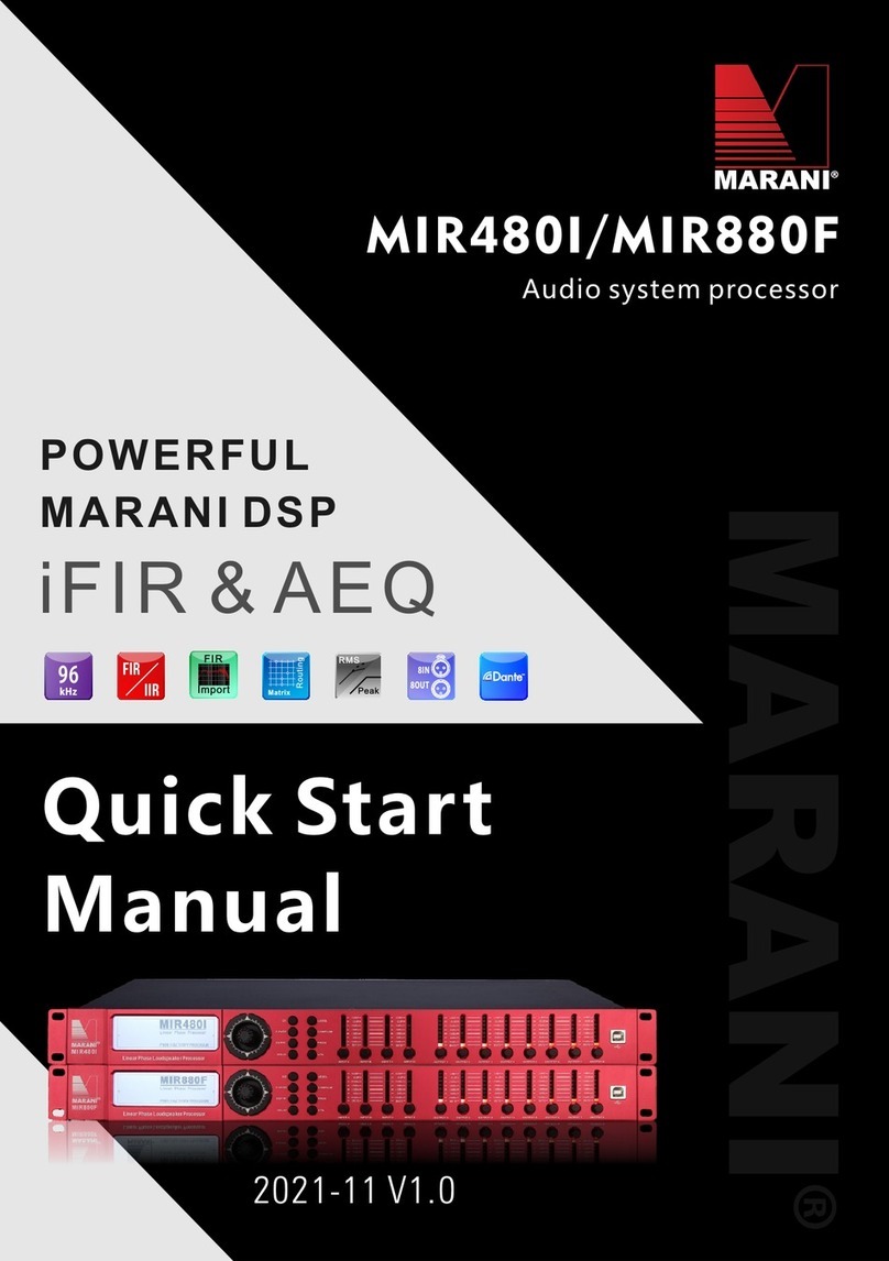
Marani MIR480I Instruction manual

Marani

Marani MIR480I Instruction manual

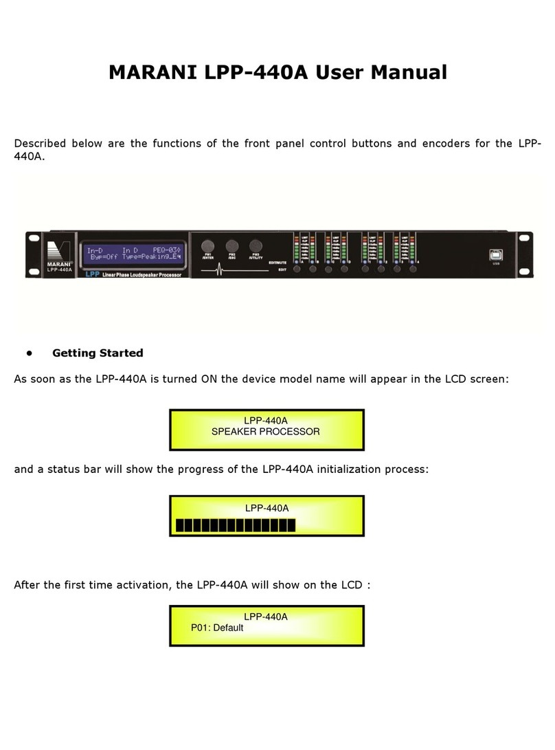
Marani LPP-440A User manual

Marani

Marani LPP-440A User manual

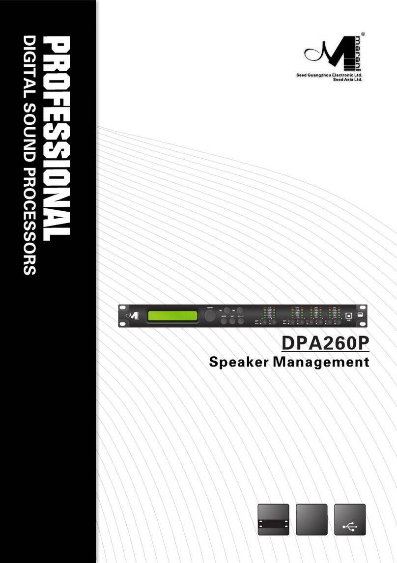
Marani DPA260P User manual

Marani

Marani DPA260P User manual

Popular Computer Hardware manuals by other brands

Toshiba TOSVERT VF-MB1/S15 IPE002Z Function manual

Toshiba

Toshiba TOSVERT VF-MB1/S15 IPE002Z Function manual

Shenzhen MEITRACK MVT380 user guide

Shenzhen

Shenzhen MEITRACK MVT380 user guide

TRENDnet TEW-601PC - SUPER G MIMO WRLS PC CARD user guide

TRENDnet

TRENDnet TEW-601PC - SUPER G MIMO WRLS PC CARD user guide

StarTech.com CF2IDE18 instruction manual

StarTech.com

StarTech.com CF2IDE18 instruction manual

Texas Instruments LMH0318 Programmer's guide

Texas Instruments

Texas Instruments LMH0318 Programmer's guide

Gateway 8510946 user guide

Gateway

Gateway 8510946 user guide

Devon IT TC2D Quick setup guide

Devon IT

Devon IT TC2D Quick setup guide

Krüger & Matz Air Shair2 owner's manual

Krüger & Matz

Krüger & Matz Air Shair2 owner's manual

Crystalio VPS-2300 quick guide

Crystalio

Crystalio VPS-2300 quick guide

MYiR FZ3 user manual

MYiR

MYiR FZ3 user manual

Protech Systems BC-K200 Quick reference guide

Protech Systems

Protech Systems BC-K200 Quick reference guide

Miranda DENSITE series DAP-1781 Guide to installation and operation

Miranda

Miranda DENSITE series DAP-1781 Guide to installation and operation

Sierra Wireless Sierra Wireless AirCard 890 quick start guide

Sierra Wireless

Sierra Wireless Sierra Wireless AirCard 890 quick start guide

Leadtek Killer Xeno Pro Quick installation guide

Leadtek

Leadtek Killer Xeno Pro Quick installation guide

Star Cooperation FlexTiny 3 Series Instructions for use

Star Cooperation

Star Cooperation FlexTiny 3 Series Instructions for use

Hotone Ampero user manual

Hotone

Hotone Ampero user manual

Connect Tech Xtreme/104-Express user manual

Connect Tech

Connect Tech Xtreme/104-Express user manual

Yealink WF50 user guide

Yealink

Yealink WF50 user guide

manuals.online logo
manuals.online logoBrands
  • About & Mission
  • Contact us
  • Privacy Policy
  • Terms and Conditions

Copyright 2025 Manuals.Online. All Rights Reserved.

DPA480
User Manual
Described below are the functions of the front panel control buttons and encoders for the DPA480.
• Getting Started
As soon as the DPA480 is turned ON the device model name will appear in the LCD screen:
and a status bar will show the progress of the DPA480 initialization process:
After the first time activation, the DPA480 will show on the LCD :
4 IN 8 OUT
SPEAKER PROCESSOR
4 IN 8 OUT
4 IN 8 OUT
P01: Default
• Encoders and ENTER, ESC buttons
The DPA480 is equipped with 3 Relative Encoders, “PM1”, “PM2” and “PM3”, These encoders allow
you to navigate the user interface and edit sections of the processor. They allow the user to
navigate within the screen for the selection of sub-menus, pages and parameters and to select the
values to be assigned during the editing operations.
The “ENTER” and “ESC” buttons allow the user to confirm or NOT confirm the operations
performed by the encoders.
• UTILITY, A/B/C/D and 1/2/3/4/5/6/7/8 buttons
The UTILITY button allows the User to enter the Sub-menus and set the general characteristics of
the Processor. The A , B , C and D buttons allow the User to enter the Editing Menus of the
Processor's Input Channels and buttons 1, 2, 3 , 4, 5, 6, 7 and 8 allow the User to enter the
Editing Menus of the Processor's Output Channels.
The A , B , C and D buttons as well as the 1, 2, 3 , 4, 5, 6, 7 and 8 buttons have double functions
dependent on the push and hold time.
When the A , B , C and D buttons are pushed and held for more than one second Input Channels
A or B or C or D are either muted or unmuted. The red LED will illuminate when the Channel is
muted. When the “MUTE” LED is OFF, then the related Input Channel is UN-MUTED.
A momentary push of the A , B , C and D buttons enters the Editing Mode for the Input Channels
(see later for the Input Channel Editing details).
The blue “EDIT” LED will now be ON.
When the 1, 2, 3 , 4, 5, 6, 7 and 8 buttons are pushed and held for more than one second the
Output Channels 1, 2, 3 , 4, 5, 6, 7 and 8 are either muted or unmuted. The red LED will
illuminate when the Channel is muted. When the “MUTE” LED is OFF, then the related Output
Channel is UN-MUTED.
A momentary push of the 1, 2, 3 , 4, 5, 6, 7 and 8 buttons enters the Editing Menu for the Output
Channels (see later for the Output Channel Editing details). The blue “EDIT” LED will now be ON.
• DPA480 Menu and Sub-Menu Structures
As stated above, the start-up default screen is the following factory preset:
From this point, sub-menus are accessed and exited using the UTILITY”, “A/B/C/D”,
“1/2/3/4/5/6/7/8”, “ENTER” and “ESC” buttons and all parameters and values are navigated by
the “PM1”, “PM2” and “PM3” encoders. Please refer to the following menu structures:
4 IN 8 OUT
P01: Default
MENU “UTILITY MENU” [Access by pushing the “UTILITY” button]
PM1 Encoder PM2 or PM3 Encoder
[to navigate between menus] [to chose option, then ENTER to load it;
(*) indicates the selected option]
1 UTILITY MENU:......
<< System Utilities >>
1.1SYSTEM UTILITY: Input Source
<< Input Source >> Source = Analog input
Source =Digital Input
Source = Noise Gen
1.2SYSTEM UTILITY: Noise Generator
<< Noise Generator >> Type = Pink
Type = White
Lev = 0dB
:
Lev:-40Db
1.3SYSTEM UTILITY: Delay Units
<< Delay Units >> Unit = Time(ms)
Unit = Distance (m)
1.4SYSTEM UTILITY: Set Default Value
<< Set Default Value >> [Enter] to confirm
1.5SYSTEM UTILITY: Firmware Version
<< Firmware Version >> Version = 3.0.2
2 UTILITY MENU:......
<< Program Utilities >>
2.1 PROGRAM UTILITY: Recall a Program
<< Recall a Program >> 01 Empty Program
: :
32 Empty Program
2.2 PROGRAM UTILITY: Save a Program
<< Save a Program >> 01: Empty Program
: :
32: Empty Program
2.3 PROGRAM UTILITY: Delete a Program
<< Delete a Program >> 01: Empty Program
: :
32: Empty Program
3 UTILITY MENU:......
<< Interface Utilities >>
3.1 INTERFACE UTILITY: Interface Setup
Interface Setup Source =USB
Source =RS485 ID=1,…,32
Source =TCP/IP DHCP=On/Off
Set IP address IP=192.168.000.01-- 254
4 UTILITY MENU:......
<< Security Utilities >>
4.1 SECURITY UTILITY: Parameter will
Show Parameter be shown
not be shown
4.2 SECURITY UTILITY: Lock Unit
Lock Unit Lock: Off
Lock: On
4.3 SECURITY UTILITY: Change Password
Change Password [ ]
4.4 SECURITY UTILITY: Enter Password
Lock With Password [ ]
ENTER
ESC
ENTER
ESC
ENTER
ESC
ENTER
ESC
ENTER
ESC
ENTER
ESC
ENTER
ESC
ENTER
ESC
ENTER
ESC
ENTER
ESC
ENTER
ESC
ENTER
ESC
ENTER
ESC
ENTER
ESC
ENTER
ESC
ENTER
ESC
ENTER
ESC
MENU “Input A/B/C/D” Input Channels Editing [Access by pushing the “A/B/C/D” button]
PM1 Encoder PM1 Enc. PM2 Enc. PM3 Enc.
[to navigate between menus] [to chose values for the parameters, no need to confirm the chosen values,
which are automatically loaded during the encoders use]
1. In- A/B/C/D [Name] Name
Name = [Name]
-> Name = _ (For Editing the Device's Name, refer to the Details on the“Utility Menus Use” Section)
2. In- A/B/C/D [Name] N.Gate
Bypass=On
-> Bypass=On PM1 N/A. Byp=On/Off Thr=-80.0dBu …-50 dBu
Rel=10ms …1000ms Atk=1ms …1000ms
3. In- A/B/C/D Gain
Gain = + 0.0 dB
-> Gain = + 0.0 dB PM1 N/A. -18 dB 0.1dB
::
+12dB 0.9dB
Step 1dB Step 0.1dB
4. In- A/B/C/D Delay
Delay = 0.000 ms
-> Delay = 0.000 ms PM1 N/A. 000.0000mS 000.0000mS
[1 ms steps] [10.4 us steps]
480.0000mS 000.9984mS
5 In- A/B/C/D [Name] Phase
Phase=Normal
-> Phase=Normal PM1 N/A. Phase= Normal/Invert
6. In- A/B/C/D [Name] RMS Cmp
Bypass=On
-> Bypass=On PM1 N/A. Byp=On/Off
PM1 N/A. Threshold=+20dBu …-10dBu
PM1 N/A. Ratio =2:1 …32:1 Knee=0% … 100%
PM1 N/A. Rel=0.1sec …3.0sec Atk=5ms … 200ms
PM1 N/A. Make-up=-12dB …+12dB
7. In- A/B/C/D [Name] EQ Byp
Bypass=On
-> Bypass=On PM1 N/A. Byp=On/Off
8. In- A/B/C/D [Name] PEQ-XX(00 to 30)
Byp=on Type=Peaking_Eq
-> Byp=on Type=Peaking_Eq PM1 N/A. Byp=On/Off Type=Peaking_Eq/ Hi Shelv
1/ Hi Shelv 2/ Hi Shelv Q/ Lo Shelv 1/ Lo Shelv 2/Lo Shelv Q/ Lo Pass 1/ Low-Pass 2/Low Pass Q/HighPass1/ HighPass2/HighPass Q/Band-Pass/ Notch Filt/All Pass
1/All Pass 2
Type=Peaking_Eq PM1 N/A. Frequency=20Hz …20000Hz
PM1 N/A. Gain=-15dB …+15dB Q=0.4 …128
Type= Hi -Shelv 1/ Hi -Shelv 2 PM1 N/A. Frequency=20Hz …20000Hz
ENTER
ESC
ENTER
ESC
ENTER
ESC
ENTER
ESC
ENTER
ESC
ENTER
ESC
ENTER
ESC
ENTER
ESC
PM1 N/A. Gain=-15dB …+15dB Q=Fixed
Type= Hi -Shelv Q PM1 N/A. Frequency=20Hz …20000Hz
PM1 N/A. Gain=-15dB …+15dB Q=0.1 …5.1
Type= Lo-Shelv 1/ Lo-Shelv 2 PM1 N/A. Frequency=20Hz …20000Hz
PM1 N/A. Gain=-15dB …+15dB Q=Fixed
Type= Lo-Shelv Q PM1 N/A. Frequency=20Hz …20000Hz
PM N/A. Gain=-15dB …+15dB Q=0.1 …5.1
Type= Low Pass 1/ Low Pass 2 PM1 N/A. Frequency=20Hz …20000Hz
Type= Low Pass Q PM1 N/A. Frequency=20Hz …20000Hz
PM1 N/A. Gain=-Fixed Q=0.1 …5.1
Type= Hi ghPass1/ Hi ghPass2 PM1 N/A. Frequency=20Hz …20000Hz
Type= Hi ghPass Q PM1 N/A. Frequency=20Hz …20000Hz
PM1 N/A. Gain=-Fixed Q=0.1 …5.1
Type= Band-Pass PM1 N/A. Frequency=20Hz …20000Hz
PM1 N/A. Gain=-15dB …+15dB Q=4 …104
Type= Notch Filt PM1 N/A. Frequency=20Hz …20000Hz
PM1 N/A. Gain=Fixed Q=4 …104
Type= All Pass 1 PM1 N/A. Frequency=20Hz …20000Hz
Type= All Pass 2 PM1 N/A. Frequency=20Hz …20000Hz
PM1 N/A. Gain=Fixed Q=4 …104
MENU “Output 1/2/3/4/5/6/7/8” Output Channels Editing [Access by pushing the “1/2/3/4/5/6/7/8”
button]
PM1 Encoder PM1 Enc. PM2 Enc. PM3 Enc.
[to navigate between menus] [to chose values for the parameters, no need to confirm the chosen values,
which are automatically loaded during the encoders use]
1. Output[x] [Name] Name
Name = [Name]
-> Name = _ (For Editing the Device's Name, refer to the Details on the“Utility Menus Use” Section)
2. Output[x] [Name] Routing
A=On B=Off C=Off D=Off
->InA: Level=0dB On PM1 N/A 0 dB On/Off
:
-30dB
->InB: Level=0dB Off PM1 N/A 0 dB On/Off
:
-30dB
->InC: Level=0dB Off PM1 N/A 0 dB On/Off
:
-30Db
->InD: Level=0dB Off PM1 N/A 0 dB On/Off
:
-30Db
3. Output[x] [Name] Gain
Gain = + 0.0 dB
-> Gain = + 0.0 dB PM1 N/A -18 dB 0.1dB
::
+12dB 0.9dB
Step 1dB Step 0.1dB
4. Output[x] [Name] Delay
Delay = 0.000 ms
-> Delay = 0.000 ms PM1 N/A 000.0000mS 000.0000mS
[1 ms steps] [10.4 us steps]
270.0000mS 000.9984Ms
5. Output[x] [Name] Phase
Phase=Normal
-> Phase=Normal PM1 N/A. Phase= Normal/Invert
6. Output[x] [Name] RMS Cmp
Bypass=On
-> Bypass=On PM1 N/A. Byp=On/Off
PM1 N/A. Threshold=+20dBu …-10dBu
PM1 N/A. Ratio =2:1 …32:1 Knee=0% … 100%
PM1N/A. Rel=0.1sec …3.0sec Atk=5ms … 200ms
PM1 N/A. Make-up=-12dB …+12dB
7. Output[x] [Name] Limiter
Bypass=On
-> Bypass=On PM1 N/A. Bypass= On/Off
PM1 N/A. Threshold=-10dBu …20 dBu
PM1 N/A. Rel=0.1sec …5sec Atk=1ms …900ms
8. Output[x] [Name] HPF
ENTER
ESC
ENTER
ESC
ENTER
ESC
ENTER
ESC
ENTER
ESC
ENTER
ESC
ENTER
ESC
20.0 Hz Bypass
-> 20.0 Hz Bypass PM1 N/A [Freq.] 20Hz [Type/Slope] Bypass
: :
20kHz LR -48 dB /Oct
Slope=Bypass/ BW -6 dB/Oct / BW -12 dB/Oct / LR -12 dB/Oct / BS -12 dB/Oct / BW -18 dB/Oct / BW -24 dB/Oct / LR -24 dB/Oct / BS -24
dB/Oct / BW -36 dB/Oct / LR-36 dB/Oct / BW -48 dB/Oct / LR-48 dB/Oct /
9. Output[x] [Name] LPF
20.0 Hz Bypass
-> 20.0 Hz Bypass PM1 N/A [Freq.] 20Hz [Type/Slope] Bypass
: :
20kHz LR -48dB/Oct
Slope=Bypass/ BW -6 dB/Oct / BW -12 dB/Oct / LR -12 dB/Oct / BS -12 dB/Oct / BW -18 dB/Oct / BW -24 dB/Oct / LR -24 dB/Oct / BS -24
dB/Oct / BW -36 dB/Oct / LR-36 dB/Oct / BW -48 dB/Oct / LR-48 dB/Oct /
10. Output[x] [Name] EQ Byp
Bypass=On
-> Bypass=On PM1 N/A. Byp=On/Off
11. Output[x] [Name] PEQ-XX(00 to 11)
Byp=on Type=Peaking_Eq
-> Byp=on Type=Peaking_Eq PAR1 N/A. Byp=On/Off Type=Peaking_Eq/ Hi -Shelv
1/ Hi -Shelv 2/ Hi -Shelv Q/ Lo-Shelv 1/ Lo-Shelv 2/Lo-Shelv Q/ Low-Pass 1/ Low-Pass 2/Low-Pass Q/High-Pass1/ High-Pass2/High-Pass Q/Band-Pass/ Notch
Filt/All Pass 1/All Pass 2
Type=Peaking_Eq PM1 N/A. Frequency=20Hz …20000Hz
PM1 N/A. Gain=-15dB …+15dB Q=0.4 …128
Type= Hi -Shelv 1/ Hi -Shelv 2 PM1 N/A. Frequency=20Hz …20000Hz
PM1 N/A. Gain=-15dB …+15dB Q=Fixed
Type= Hi -Shelv Q PM1 N/A. Frequency=20Hz …20000Hz
PM1 N/A. Gain=-15dB …+15dB Q=0.1 …5.1
Type= Lo-Shelv 1/ Lo-Shelv 2 PM1 N/A. Frequency=20Hz …20000Hz
PM1 N/A. Gain=-15dB …+15dB Q=Fixed
Type= Lo-Shelv Q PM1 N/A. Frequency=20Hz …20000Hz
PM1 N/A. Gain=-15dB …+15dB Q=0.1 …5.1
Type= Low-Pass 1/ Low-Pass 2 PM1 N/A. Frequency=20Hz …20000Hz
Type= Low-Pass Q PM1 N/A. Frequency=20Hz …20000Hz
PM1 N/A. Gain=-Fixed Q=0.1 …5.1
Type= High-Pass1/ High-Pass2 PM1 N/A. Frequency=20Hz …20000Hz
Type= High-Pass Q PM1 N/A. Frequency=20Hz …20000Hz
PM1 N/A. Gain=-Fixed Q=0.1 …5.1
Type= Band-Pass PM1 N/A. Frequency=20Hz …20000Hz
PM1 N/A. Gain=-15dB …+15dB Q=4 …104
Type= Notch Filt PM1 N/A. Frequency=20Hz …20000Hz
PM1 N/A. Gain=Fixed Q=4 …104
Type= All Pass 1 PM1 N/A. Frequency=20Hz …20000Hz
Type= All Pass 2 PM1 N/A. Frequency=20Hz …20000Hz
PM1 N/A. Gain=Fixed Q=4 …104
ENTER
ESC
ENTER
ESC
ENTER
ESC
ENTER
ESC
Menu “UTILITY” [access by pushing the “UTILITY” button]
From the “Default Screen”, it is possible access the “UTILITY” menu pushing the “UTILITY” button
and the Sub-Menus pages can be selected just rotating clockwise and counter-clockwise the
“PM1” encoder.
Once selected the sub-menu page, using the “ENTER” button can be accessed the Sub-Menus
pages, again “scrollable” using the “PM1” encoder and accessible for the parameters' editing
pushing again the “ENTER' button.
Note: In each sub-menu choice, the current selected or running choice is what shown on the LCD
screen.
System Utilities Sub-menu – this sub-menu allows to access several operations related to the
DPA480 Start Up and General Configuration:
UTILITY MENU:
From the “System Utilities Sub-menu”, pushing “ENTER” and then using the “PM1” encoder for
scrolling will give access to the following pages:
−Input Source:the DPA480 is equipped with 4 Analog Inputs (Balanced Female XLR) and 2
AES Digital Input (RCA connector).and noise generator
The “Input Source” page allows you to select the desired Input type:
By pressing ENTER on Input Source and then rotating the “PM2” or “PM3” encoders, it is
possible to select the Main Inputs for the DPA480, allowing the User to choose between
Analog , AES Digital Input or Noise Generator.
The selection can be confirmed by pressing the “ENTER” button.
The following screen shows that the Analog Input has been selected:
UTILITY MENU:
UTILITY MENU
--
System Utilities
--
SYSTEM UTILITY
-- Input Source --
Input Source
Source = Analog input
UTILITY MENU:
−
−Noise Generator:DPA480 equips with 2 types of noise generator: White Noise and Pink
Noise.
By pressing ENTER and rotating the “PM2” encoder, it is possible to select between those 2
choice: “Pink” or “White”. By rotating the “PM3” encoder, it is possible to set the value of level
of white noise generator and pink noise generator, with whose range from 0dB to -40dB.
The following screen shows the selected pink noise with level of -20dB:
Delay Units: this page allows you to select the measurement unit to be used for the Delays:
Time (in milliseconds “ms”) or Distance (in meters “m”):
By pressing ENTER button and rotating the “PM2” or “PM3” encoder, it is possible to select the
measurement unit to be used for the delay, which will be confirmed by pushing the ENTER
button.
The following screen shows the selected delay measurement is Time (milliseconds)
Set Default Value: All setting for DPA480 can be set to default value:
By pressing ENTER button, will show up the following screen of an interface to confirm to set
the default value:
By pressing ENTER button one more time, will show up the following screen:
SYSTEM UTILITY
-- Delay Units --
Delay Units
Unit : = Time (ms) *
SYSTEM UTILITY
-- Noise Generator --
Noise Generator
Type=Pink Lev=-20dB
SYSTEM UTILITY
-- Set Default Value --
Set Default Value
[Enter] to confirm