manuals.online logo
Brands
  1. Home
  2. •
  3. Brands
  4. •
  5. Marantz
  6. •
  7. Receiver
  8. •
  9. Marantz SR1100L User manual

Marantz SR1100L User manual

Other Marantz Receiver manuals

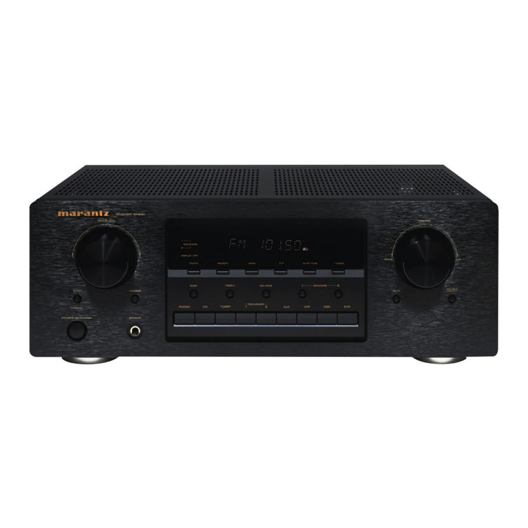
Marantz SR5000/N1B User manual

Marantz

Marantz SR5000/N1B User manual

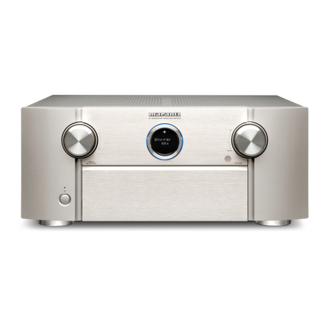
Marantz PS2100N1S User manual

Marantz

Marantz PS2100N1S User manual

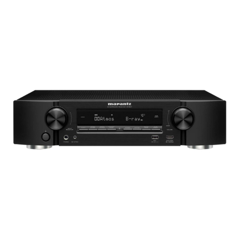
Marantz SR6006/U1B User manual

Marantz

Marantz SR6006/U1B User manual

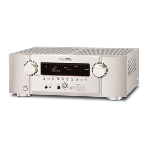
Marantz 2325 User manual

Marantz

Marantz 2325 User manual

Marantz SR6009 User manual

Marantz

Marantz SR6009 User manual

Marantz SR7008 User manual

Marantz

Marantz SR7008 User manual

Marantz SR5008 Product information sheet

Marantz

Marantz SR5008 Product information sheet

Marantz SR7005 User manual

Marantz

Marantz SR7005 User manual

Marantz SR6008 Quick start guide

Marantz

Marantz SR6008 Quick start guide

Marantz SR-6001 User manual

Marantz

Marantz SR-6001 User manual

Marantz SR7008 User guide

Marantz

Marantz SR7008 User guide

Marantz SR4320/A1B User manual

Marantz

Marantz SR4320/A1B User manual

Marantz 2235B User manual

Marantz

Marantz 2235B User manual

Marantz SR5005 User manual

Marantz

Marantz SR5005 User manual

Marantz SR-12S1 User manual

Marantz

Marantz SR-12S1 User manual

Marantz SR5003 User manual

Marantz

Marantz SR5003 User manual

Marantz SR5010 User manual

Marantz

Marantz SR5010 User manual

Marantz SR7000 User manual

Marantz

Marantz SR7000 User manual

Marantz SR5400 User manual

Marantz

Marantz SR5400 User manual

Marantz NR1504 User manual

Marantz

Marantz NR1504 User manual

Marantz NR1504 User manual

Marantz

Marantz NR1504 User manual

Marantz SR5002N1B User manual

Marantz

Marantz SR5002N1B User manual

Marantz Slim-line NR1501 User manual

Marantz

Marantz Slim-line NR1501 User manual

Marantz SR680 User manual

Marantz

Marantz SR680 User manual

Popular Receiver manuals by other brands

Televes ZAS HD SAT user manual

Televes

Televes ZAS HD SAT user manual

Realistic DX-75 Operating and service instructions

Realistic

Realistic DX-75 Operating and service instructions

Saris 4620 Assembly instructions

Saris

Saris 4620 Assembly instructions

Mini DTR 206C PVR user manual

Mini

Mini DTR 206C PVR user manual

RF Elements TwistPort manual

RF Elements

RF Elements TwistPort manual

Denon DN-200WS user guide

Denon

Denon DN-200WS user guide

Yamaha RX-V467 owner's manual

Yamaha

Yamaha RX-V467 owner's manual

Russound SaphIR 858 instruction manual

Russound

Russound SaphIR 858 instruction manual

Quasonix RDMS Firmware update procedure

Quasonix

Quasonix RDMS Firmware update procedure

Pioneer XV-HTD1 Service manual

Pioneer

Pioneer XV-HTD1 Service manual

ATZ HDMI-V2-44HE150 manual

ATZ

ATZ HDMI-V2-44HE150 manual

Sony XNV-770BT MyTomTom Specifications

Sony

Sony XNV-770BT MyTomTom Specifications

Grundig STR 7122 TWIN Service manual

Grundig

Grundig STR 7122 TWIN Service manual

Creative Blaster Modem user guide

Creative

Creative Blaster Modem user guide

Panduit ATLONA AT-OME-RX11 installation guide

Panduit

Panduit ATLONA AT-OME-RX11 installation guide

VOLTCRAFT UTPS-40 operating instructions

VOLTCRAFT

VOLTCRAFT UTPS-40 operating instructions

JVC KW-ADV794 instructions

JVC

JVC KW-ADV794 instructions

Litelink VT-1001 operating instructions

Litelink

Litelink VT-1001 operating instructions

manuals.online logo
manuals.online logoBrands
  • About & Mission
  • Contact us
  • Privacy Policy
  • Terms and Conditions

Copyright 2025 Manuals.Online. All Rights Reserved.

.4r;
SERVICE
MANUAL
MARANTZ DESIGN
AND SERVICE
Using
superior desiqn
and selecte.l
high
grade
components,
l\ilARANTZ
hascreatedtheultimate
in
stereosound.Onlyorlginal
l\,lARANTZ parts can insurethat your t!,4ARANTZ
product will continue
to pefformto the specLfications
{or which it is
famous.
parts
for your MARANTZ stereoare
generally
availablewithln 72 hoursthroughoutthe nation
via a toll-freellneto our
National
parts Depot in California.
The sales
professionals
who take
your call
immediatelyreferto thelrown
desktopcom_
puter terminal and can
qulckJy
determine
the availabilityand price
lnformation
yoLt
reqLrire.lf for some
reason,
your
order
shoLlld
exceed our available
stock,we usually
can
instantly
provlde
analternatereplacement
part
or current
deliveryinfor'
mation. When the order is placed
andconfirmed,the computersimultaneously
generates
"hard copy" orders
at the dlstri
bLltlon
center. As hardcopiescomedirectly
from thecomputerto thenational
partsdepot,
your requestedstock sassembled
andorepared
for shipment
and
placed
onthe
first
available
carrierior dellveryto you
ORDERING PARTS
phone orders will eliminatemail delays,
and we encourage
the useof thismetho(l. lf you orderby mail,useIVIARANTZ
parts
order
forms which
areavailablefrornour National
PartsDepotlocated
atthefollowingaddressl
The
following information
mustbesupplied
to ellminate
delaysin
processinqyo(rr
orcler:
1. Complete
address.
2. Complete
part
numbers-
3. Complete
descriptionof Parts.
4. lModelnumber
for which
part
isrequired
(indicate
MARANTZ).
5. Accountnumber
(for
accountcustomersonly).
Direct
consumers
wilL
be provided
with the current
r€taI prlve
quotation
on available
parts
in orderto advisethem ol thc
cost
of the Parts
andshiPPng
OVERSEAS PARTS ORDERING
Parts
rnaV
also
be ordered
from the
fo lowingoverseas
addresses:
Maranfz Australta
32 Cross
Street
Brookvale,N.S.W.2100 D'6072Dreieich
Marantz
GermanyGmbh MarantzAudioU.K..Ltd. MarantzSvenska
A.B.
Max'PlanckStraRe22,
Austra
lla
Maran? Eu
rope, S.A
326,
Avenue
Louise
Boite32
1050 Brussels
Belgrum
WestGermany
MarantzBelgium
193,LondonRoad
STA
lN
ES,
l\4idcllesex
UnitedK
ingdom
Marantz France
Franzengatan6
10425
Stockholm
S\,veden
Marantz
NorskeA.S.
Refstadaileen13
Oslo
5
Norway
45 qJe ALg-srp
VanTrnc 4 Rro Ber
rardDal
s.r
92600
Asnieres
France
1080Brussels
Belgium
All of the
above
locationsare
fu ly equippedto takecareof yolrr
tota service
needs.
Because
various
countries
havediffering
con{iguration
requirements,
it isnecessary
that you contactthe service
facilityln your particular
country. In lheeventthat
there
is
no service
locationlistedfor your
country,
p easeconlactthenearestfacilityfor the
necessaryasslstance.
rrr-rr-alrt_-
1.
2.
J.
4.
q
TABLEO
FCONTENTS
P.W.
BOARDS
TEST
EOUIPMENT
REOUIRED
FOR
SERVICING
' ...
ALIGNMENT PROCEDURES
VOLTAGE
CONVERSION
DIAGRAM AND COMPONENT
LOCATIONS
5.1 Main Amp. & Powersuppty
(P700)
Schematic
Diagram
and
Component
Locations
' - - " ' 6
5.2 Antenna/Osc
{PBOO)
Schematic
Diagram
andComponent
Locations "'--- "' 6
5.3 Signal
& Tuning
LED
(PX00)Schematic
Diagram
andComponent
Locations 8
5.4 Tuner {P100) Schematic
Diagram
andComponent
Locations I
5.5 switch Assembly
(PS00)
Diagram
andcomponent
Locations. " " " " 10
5.6 Speaker
Terminal
(PTO0)
Diagram
andComponent
Locations
. " " ' 10
5,7 Power
Switch (PUOo)
Diagram
andComponent
Locations
. . . " " " l0
6.
8.
9.
BLOCK DIAG
RAM .. .
13
EXPLODED
VIEWS
AND PARTSLIST
TECHNICAL SPECIFICATIONS
SCHEMATIC
DIAG
RAM 26
1a
"-
INTRODUCTION
This service
manual was
prepared
for useby Authorized
Warranty Stations and containsservice
information for
lMarantz
lvlodel
SF1
100L
Stereophonic
Receiver.
Servicing
information and voltage
data includedin this
manual
are intended for useby the knowledgeableandex
perienced
technician only- All instructionsshouldbe
read
carefully. No atternpt should be madeto proceed
without
a
goodunderstanding
of theoperationof the receiver.
The partslist {urnishes
informationby whichreplacement
parts may be ordered Jromthe N4aranlzCompany.A simple
description
is included
for parts
which
canusuallybe ob'
tained
through local
suPPliers
2. TEST EOUIPMENT
REOUIRED
FOR SERVICING
Item Manufacturerand Model No.
AlvlSignal
Generator
't.P.w.BoABDS
As can be seenfrom the circuit diagramthe chassisof
l4odelSR1100L
cons]stsof the
following
units. Each
unit
mounted
on a printed
circuit
board
isdescribedwithinthe
squareenclosedby a bold dotted line on the circuit dia-
gram.
1. Tuner. . - mountedon P-W.BoardP100
2. Main
Amp/PowerSupply
. mountedon P.W.BoardP700
3. Volume/BalancePush
Switch
mounted on P.W.BoardPS00
4. Speaker
Terminal . . . . mountedon P.W.Baord
PT00
5. TuningLED . . . .. .. mountedonP.W.BoardPX00
6. AntennaCoil mountedon P.W.BoardPB00
7. Power
Switch mountedon P.W.BoardPU00
Use
Signal
sourcefor AM alignment
TestLoop Usewlth AM SignalGenerator
FIMSignal
Generator SoundTechnology Signalsource
for FM
alignment
MPXOscillatoradjLrstment
(VCO
)
Troubleshooting
Voltagemeasurements
(DC)
lvlonitors
primary powerto amplif
ier
Stereo
separationalignmentandtroLrble
shootrng
Distortionmeasurements
Sinewave
and squarewavesignaJsourc-"
Voltagemeasurements
lAC)
Waveform
analysisandtrouble
shootingand
ASO
alignment
Oscilloscope
FrequencY
Cou
nter FlukeModel19004
Flukpl\,4odel
8000
"Dig.tal"
Simpson
f\4odel313,TripletModel801
SimpsonModel
1379
CommercialGrade
(1-10A)
Simpson
Model1359
TektronixModelT932
Philipsl,.4odel3232
SuperiorElectronicCo.,
Circuit
Tester
DC
VTVM
AC Wattmeter
Output
Load
r0.5%,100w)
ACAmmeter
Line
Voltmeter
Variable
Autotransformer
Shorting
Plug
Powerstat
l\4odel1168-10A
lMonitorsamplifier
output
undershortcrrcut
condition
Monitors
potential
of primarypower
to
am
p
lifier
Use
phonoplug
with 600-ohm
acrosscenter
pin
andshell
CommercialGrade
Shorts
amplifierinputto eliminate
norse
p
rcKLr
p
Adjusts'evelot pr
mary
power
to dmp
if er
Provides8-ohm
loadJor
amplifier
output
termrnarron
This
table
lists
the testequipment
requiredfor servicing
the N4odelSR
1
100LReceiver'
CommercialGrade
Output
Load
10.5%,
100w) Provides4 ohm oadfor amplifieroutput
rermtna(ton
SRl1OOL
TUNER
P.W.
BOARD
g [.]
@@
@
I l@*
Mwlw I I Lw Mw
wl--lw
Figure2. Adjustment Point Locations
3. ALIGNMENT
PROCEDURES
A dummy
resistor
of 47k-ohms
must
beconnectedacrossthetuneroutputterminals
beforealignment.
3.1 FMAlignmentProcedures
(Function
switchinthe
"FM" position)
FlvlRFAlignment
3,3 MultiplexAlignmentProcedures
(Function
switchin
the
"FM" position/Mode
switchinthe
"STEREO" position)
St€p SignalSo0rc6
Conneclion Signal Indicttor
Connoction s€(rheoigitll
Roadout
Frrquonry Adrurt
IRF generalor
to
terminalsthrough
matchingnetwork
(300
ohms,balanced)
lMaintain
RF lev6l
belowlimit.)
87.4
MHz
channeloutput
Tuningcapacitor
minimum closed. L106
formaximum
outpui.
2108.2MHz Tuningcepacitor C
118lor
maximum
outpur,
90 lvlHz 90 lvlHz L101,
L103
formaximum
4106MHz 106 MHz ANT. RF.TRIM. CAP.
tor maximum output,
5Repeat
steps
1
to 4.
6Checkoverallresponsecurveandrepeatabovestepsas
necessarv
to obtainmaximum sensirivaty,
1No signal
"0" center
meter
or DCcurrent
mererin 100pA
J2O1andJ2O2
L2O1primery
core
so
thal the meterindacales
its center or may read
"O". (RED core)
8RF g€nerator
1mV {or
300pV, only Step 10)
outpul lo Flvl
antenna
terminalsth.ough
matching
network,
{300
ohms,balanced)
98MHz Distortionmeter
to
L or R channel
ourpur 98 MHz L201 Secondary
core
(BLK)forminimum
distor-
10 98 lvtHz 98MHz R219 sothat sign6lstrength
LED may light5 points.
3.2 MutingCircuitAlignment
Stop SignalSource
Connection Sign.l lrdicator
Connection Set ths Digiral
R€adoul FrGqu€ncy Adiun
RF generator
12.5pV
output to FM antenna
terminalsthrough
matchingnetwork
(30O
ohrns,
balancedl
98 MHz channeloutput 98
MHz
F.213 tor 12.5pV
thresholdlevel.
(During
this adjustment
turn the
muting pushswitch
"oN".)
Stop Sign.l Source
Connoction Signal Indicator
Connoclion $t rhaoigit.l
R@doui
Frequency Adjust
RF generator
to Flvl
antennatermrnals
throughmatching
network (300
ohms,
balanced),
with 1mV
Fl!4
stereosimulator
RF leveland 10096
modulation
{pilor9%)
Frequency
counter
to J301
98 MHz
R304
sothat
Frequency
countermaypreciselY
re6d
76 kHz.
2Stereo, left
(1,00O
Hz) VTVM to right R331 lor maximum
outpul and sameseparatlon
in both channels.
Stereo,right
{1,0O0
Hz) channeloutput
Pilot
only output 98 MHz R307
torminimum
outputand
same
outputin
bothchannels,
3.4 AM AlignmentProcedures
(Function
iwitchinthe
"AM" position)
'1
. AM lFAlignment
Stop Sign.l So(l
rc.
Conn6ction Sign.l lndicator
Connsction SorDbl
Pointertoi Adiun
1Sweepgenerator to
OSCVariable
Cap. 450
kHzmarker Oscilloscope
to T.P. Ouietpoint on band LA02& LAO3
form6ximum
anosymmetflcresponse.
2. MWRFAlignment
3. LWRFAlignment
TestLoop
FigurB3. Application of AM Signtl
St.p Signal Sourca
Conmction Signal lndic.tor
Connoction S€tthoDioir.l
Reado0t
Fr€qu6ncy Adjust
Apply thesignalto
theAM barantenn€
from rhe RF generator,
using
thetest
loop.
as
perthe Figure
2.
520
kHz
channel
output
Tuningcapacitor
minimum closed. LB04
for maximumoutput,
1,630kHz Tuningcapacitor CBO2formaximumoutput.
600kHz 600
kHz LB01for maximumoutput.
41,400
kHz 1,400
kHz CB01
for maximumoutput.
Rep€atsteps1 to 4 d necessaryto obtainmaximumsensitivity.
Al\4Loop Antenna
Stop Sigrul SoU
rce
C,onn€ction Signal lndic€tor
Connection Set
ohl
Pointorto Adjun
I
RF g€norator
to
Alvl an'tenna
t6rminals
through IHF dumrrry
145kHz 'l45
kHz
wirh
tuning
gang
closed. L803for maximumoutput.
2380
kHz 380
kHzwith
tuning
gang
op€n. CB02
formaximumoutput.
't70
kHz 170kHz LB02for rmximumoutpul.
4350
kHz 350
kHz CBo1
formaximum
output.
5450kHz Tuning
geng
clos6d. LB05forminimumoutput.
Rep€at
steps
1to 4 as
necossaryto obtainmaximumsenritivity.
4. VOLTAGE
CONVERSION
To convertthe unit to a djfferent
power
source
voltage,
change
the
position
as
illustrated
in
thedrawing
below.
CAUTION:DISCONNECTPOWER
SUPPLYCORD
FROM
ACOUTLET
BEFORE
CONVERTING
VOLT.
AGE. DO NOT DISASSEMBLE
THE VOLT-
AGESELECTOR
ABSOLUTELY.
220v ?2AV
-
(T)V€rsions
Figure 3, Voltage Convstsion
(Note
onsafety:The
parts
markedwith A areimportant
parts
onthesafety.Pleaseuse
the
parts
havingthedesignated
parts
numbers
without
fail.
)
FTZREGULATION
Instructionfor theusein the range
otherthanspecifiedin FTZcodes,
Achtungfiir die Leute,
die in demGebietwohnen,
wo die FTZ-Bestimmungen
vorherschend
sind.
SolltedasGeratauch
fiir Frequenzen
auszerhalb
desin denFTZ-Bestimmungenangegebenen
Bereichesempfangebereit
sein,
bitten wir, den Bereich
durchNachstellen
desKernes
in derOszillatorspule
(inderAbbildung
mit "FTZ" gekennzeichnet)
so
zukorrigieren,
dasserdenBestimmungen
entspricht.
5. DIAGRAM
AND COMPONENT
LOCATIONS
5.1
MainAmp.&Power
Supply
(P700)
SchematicDiagram
andComponentLocations
Woo
IMAIN
AMP
ond R7t7
3,3
roNol R736
330
(
lw)
c713
roop
e7O9 07t3
,\
+t,pv fr
POWER
SUPPLY
QKO3
A
R80t 39
(3W)
5.2Antenna/Os0
(P800)
Schematic
Diagram
and
Component
Locations
c 71rl
3,3/fiv
j
Q723 Q705
o7r
r 0715
RzrB 3,3x QNO5 czrq roop
QTIO O7l4
POWER
SUPPLY
j<
I
1
tT
-'ll -l
l--a I
'l