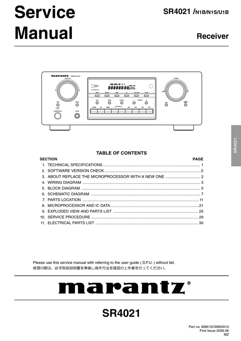
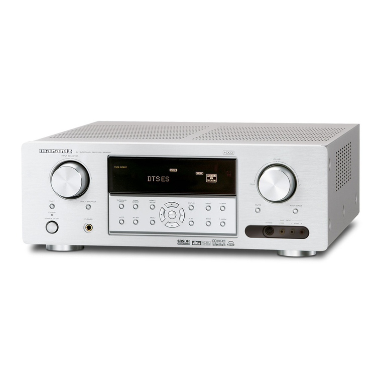
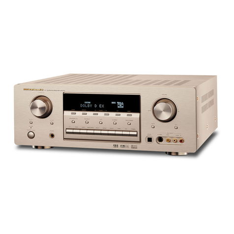
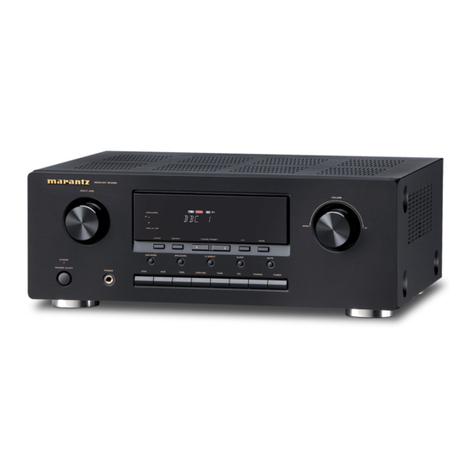
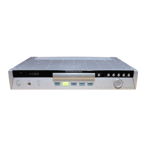
Marantz SR-4021 User manual

Model SR4021 User Guide
Receiver

ENGLISH
WARRANTY
For warranty information, contact your local Marantz
distributor.
RETAINYOUR PURCHASE RECEIPT
Your purchase receipt isyour permanent record
of a valuable purchase. It should be kept ina safe
place to be referred to asnecessary for insurance
purposesor whencorresponding with Marantz.
IMPORTANT
Whenseeking warranty service, it isthe responsibility
of the consumer to establish proof and date of
purchase. Your purchase receipt or invoice is
adequate for such proof.
FOR U.K. ONLY
Thisundertaking isinadditionto a consumer’s
statutory rightsand doesnot affect those rightsin
any way.
FRANÇAIS
GARANTIE
Pour desinformations sur la garantie, contacter le
distributeur local Marantz.
CONSERVER L’ATTESTATION D’ACHAT
L’attestationd’achat est la preuve permanente
d’un achat de valeur. La conserver enlieusur pour
s’y reporter aux fins d’obtentiond’une couverture
d’assurance oudans le cadre de correspondances
avec Marantz.
IMPORTANT
Pour l’obtentiond’un service couvert par la garantie,
il incombe auclient d’établir la preuve de l’achat
et d’encorroborer la date. Le reçuoula facture
constituent despreuvessuffisantes.
DEUTSCH
GARANTIE
Bei GarantiefragenwendenSie sich bitte anIhren
Marantz-Händler.
HEBEN SIE IHRE QUITTING GUT AUF
Die Quittung dient Ihnenalsbleibende Unterlage
für IhrenwertvollenEinkauf DasAufbewahrender
Quittung ist wichtig, da die darinenthaltenenA ngaben
für Versicherungswecke oder bei Korrespondenz mit
Marantz angeführt werdenmüssen.
WICHTIG!
BeiGarantiefragenm ußderKundeeineKaufunterlage
mit Kaufdatum vorlegen. IhrenQuittung oder
Rechnung ist alsUnterlage ausreichend.
NEDERLANDS
GARANTIE
Voor inlichtingenomtrent garantie dient uzich tot uw
plaatselijke Marantz.
UW KWITANTIE, KASSABON E.D. BEWAREN
Uw kwitantie, kassabone.d. vormenuw bewijs
vanaankoop vaneenwaardevol artikel endienen
op eenveilige plaatsbewaard te wordenvoor evt,
verwijzing bijv, inverbend met verzekering of bij
correspondentie met Marantz.
BELANGRIJK
Bij eenevt, beroep op de garantie ishet de
verantwoordelijkheid vande consument een
gedateerd bewijsvanaankoop te tonen. Uw
kassabonof factuurzijnvoldoende bewijs.
ESPAÑOL
GARANTIA
Para obtener informaciónacerca de la garantia
póngase encontacto consu distribuidor Marantz.
GUARDE SU RECIBO DE COMPRA
Surecibo de compra essu prueba permanente de
haber adquirido un aparato de valor, Este recibo
deberá guardarlo enun lugar seguro y utilizarlo
como referencia cuando tenga que hacer uso del
seguro o se ponga encontacto conMarantz.
IMPORTANTE
Cuando solicite el servicio otorgado por la garantia
el usuario tiene la responsabilidad de demonstrar
cuándo efectuó la compra. Eneste caso, su recibo
de compra será la prueba apropiada.
ITALIANO
GARANZIA
L’apparecchio è coperto da una garanzia di buon
funzionamento della durata di un anno, o del periodo
previsto dalla legge, a partire dalla data di acquisto
comprovata da un documento attestante il nominativo
del Rivenditore e la data di vendita. La garanzia sarà
prestata conla sostituzione o la riparazione gratuita
delle parti difettose.
Nonsono coperti da garanzia difetti derivanti da
uso improprio, errata installazione, manutenzione
effettuata da personale nonautorizzato o, comunque,
da circostanze che nonpossano riferirsi a difetti di
funzionamento dell’apparecchio. Sono inoltre esclusi
dalla garanzia gli interventi inerenti l’installazione e
l’allacciamento agli impianti di alimentazione.
Gli apparecchi verranno riparati presso i nostri Centri
di Assistenza Autorizzati. Le spese ed i rischi di
trasporto sono a carico del cliente.
La casa costruttrice declina ogni responsabilità per
danni diretti o indiretti provocati dalla inosservanza
delle prescrizioni di installazione, uso e manutenzione
dettagliate nel presente manuale o per guasti dovuti ad
uso continuato a fini professionali.
SVENSKA
GARANTI
För informationom garantin, kontakta Marantz
lokalagent.
SPAR KVITTOT
Kvittot är ett inköpsbevispå envärdefull vara. Det skall
förvarassäkert och hänvisastill vid försäkringsfall
eller vidkorrespondens mod Marantz.
VIKTIGT
Fö att garantinskall gälla är det kundens sak att
framställa bevisoch datum om köpet. Kvitto eller
faktura är tillräokligt bevisfö detta.

English
WARNINGS
- Do not expose the equipment to rainor moisture.
- Do not remove the cover from the equipment.
- Do not insert anything into the equipment through
the ventilationholes.
- Do not handle the mains cord with wet hands.
- Do not cover the ventilationwith any itemssuch as
tablecloths, newspapers, curtains, etc.
- No naked flame sources, such aslighted candles,
should be placed onthe equipment.
- Whendisposing of used batteries, please comply
with governmental regulations or environmental
public instruction’srulesthat apply inyour country
or area.
- Make a space of about 0.2 meter around the unit.
- No objectsfilled with liquids, such asvases, shall
be placed onthe equipment.
- Whenthe switch isinthe OFF position, the
equipment isnot completely switched off from
MAINS.
- The equipment shall be installed near the
power supply so that the power supply iseasily
accessible.
Français
AVERTISSEMENTS
- Ne pasexposer l’appareil à la pluie ni à
l’humidité.
- Ne pasessayer de retirer le boîtier de l’appareil.
- Ne rieninsérer dans l’appareil par lesorificesde
ventilation.
- Ne pasmanipuler le cordond’alimentationavec
lesmains mouillées.
- Ne pasrecouvrir lesouïesde ventilationavec un
objet quelconque comme une nappe, un journal,
un rideau, etc.
- Ne placer aucune source de flamme nue, comme
une bougie allumée, sur l'appareil.
- Pour mettre aurebut lespilesusées, respecter les
loisgouvernementalesoulesrèglementsofficiels
concernant l’environnement qui s'appliquent à
votre paysourégion.
- Veiller à ce qu’aucun objet ne soit à moins de 0,2
mètre descôtésde l'appareil.
- Aucun objet rempli de liquide, un vase par exemple,
ne doit être placé sur l'appareil.
- Lorsque l'interrupteur est sur la positionOFF,
l'appareil n'est pascomplètement déconnecté du
SECTEUR (MAINS).
- L'appareil sera installé prèsde la source
d'alimentation, de sorte que cette dernière soit
facilement accessible.
Deutsch
WARNHINWEISE
- DasGerät nicht Regenoder Feuchtigkeit
aussetzen.
- Die Abdeckung nicht vom Gerät abnehmen.
- Keine Gegenstände durch die Belüftungsschlitze
stecken.
- DasNetzkabel nicht mit feuchtenoder nassen
Händenanfassen.
- DeckenSie die Lüftungsöffnungennicht mit einem
Tischtuch, einer Zeitung, einem Vorhang usw. ab.
- Esdürfenkeine Gegenstände mit offener Flamme,
wie etwa brennende Kerzen, auf dem Gerät
aufgestellt werden.
- BeachtenSie bei der Entsorgung der verbrauchten
Batterienallegeltendenlokalenundüberregionalen
Regelungen.
- Auf allenGeräteseitenmuß einZwischenraum
vonungefähr 0,2 meter vorhandensein.
- Auf dasGerät dürfenkeine mit Flüssigkeiten
gefüllte Behälter, wie etwa eine Vase, gestellt
werden.
- Wenn der Schalter ausgeschaltet ist (OFF-
Position), ist dasGerät nicht vollständigvom
Stromnetz (MAINS) abgetrennt.
- DasGerät sollte inder Nähe einer Netzsteckdose
aufgestellt werden, damit esleicht andas
Stromnetz angeschlossenwerdenkann.
Nederlands
WAARSCHUWINGEN
- Stel het apparaat niet bloot aanregenof vocht.
- Verwijder de afdekplaat vanhet apparaat niet.
- Duw nietsdoor de ventilatieopeningeninhet
apparaat.
- Raak het netsnoer niet met natte handenaan.
- Bedek de ventilatieopeningenniet met enige
voorwerpen, zoalstafelkleden, kranten, gordijnen,
enz.
- Plaatsgeenbrandende voorwerpen, zoals
kaarsen, op het apparaat.
- Volgbij het weggooienvanverbruikte batterijende
overheidswetgeving of milieuvoorschriftenop die
vankracht zijninhet land of de regio waarinuzich
bevindt.
- Zorgdat er 0,2 meter vrije ruimte rond het toestel
is.
- Plaatsgeenvoorwerpenmet eenvloeistof erin,
zoalseenbloemenvaas, op het apparaat.
- Alsde schakelaar op OFF staat, ishet apparaat
niet vollediglosgekoppeld vande netspanning
(MAINS).
- Deapparatuur wordt indebuurt vanhet stopcontact
geïnstalleerd, zodat dit altijd gemakkelijk
toegankelijk is.
CE MARKING
English
The SR4021 isinconformity with the EMC directive and low-voltage directive.
Français
Le SR4021 est conforme à la directive EMC et à la directive sur lesbassestensions.
Deutsch
DasModell SR4021 entspricht denEMC-Richtlinienund denRichtlinienfür
Niederspannungsgeräte.
Nederlands
De SR4021 voldoet aande EMC eisenende vereistenvoor laag-voltage.
Español
El SR4021 está de acuerdo conlasnormasEMC y lasrelacionadasconbaja tensión.
Italiano
Il SR4021 è conforme alle direttive CEE ed a quelle per i bassi voltaggi.
Svenska
SR4021 är tillverkad i enlighet med EMC direktivenoch direktivenför lågvoltsutrusning.

Español
ADVERTENCIAS
- No exponga el equipo a la lluvia ni a la humedad.
- No extraiga la tapa del equipo.
- No introduzca nada enel interior del equipo a
travésde losorificiosde ventilación.
- No maneje el cable de alimentaciónconlas
manosmojadas.
- No cubra la ventilaciónconobjetoscomo manteles,
periódicos, cortinas, etc.
- No debencolocarse sobre el equipo elementos
confuego, por ejemplo velasencendidas.
- Cuando se eliminenbateríasusadas, deben
cumplirse lasreglamentacionesoficialeso las
normasde protecciónmedioambiental aplicables
ensu paíso ensu zona.
- Deje un espacio de unos0,2 metro alrededor de la
unidad.
- No se debencolocar sobre el aparato recipientes
que contenganlíquidos, como por ejemplo
jarrones.
- Cuando el interruptor está enla posiciónOFF, el
equipo no está completamente desconectado de
la alimentaciónMAINS.
- El equipo se instalará cerca de la fuente de
alimentaciónde manera que resulte fácil acceder
a ella.
Italiano
AVVERTENZE
- Nonesporre l’apparecchio alla pioggia o
all’umidità.
- Nonrimuovere il coperchio dell’apparecchio.
- Nonintrodurre oggetti all’interno dell’apparecchio
attraverso i fori di ventilazione.
- Nontoccare il cavo di alimentazione conle mani
bagnate.
- Noncoprire le fessure di ventilazione contovaglie,
giornali, tende od oggetti analoghi.
- Nonposare sull'apparecchio sorgenti di fiamme
scoperte quali candele accese.
- Smaltire le pile usate inconformità alle norme
governative o disposizioni ambientali vigenti nel
proprio paese o zona.
- Lasciare 0,2 metro liberi tutto intorno l'unità.
- Nonmetteresull'apparecchiatura alcun contenitore
di liquido, come ad esempio dei vasi.
- Quando l'interruttore è nella posizione OFF,
l'apparecchiatura nonè completamente scollegata
da MAINS.
- L’apparecchio va installato inprossimità della
fonte di alimentazione, inmodo che quest’ultima
sia facilmente accessibile.
Svenska
VARNINGAR
- Utsätt inte utrustningenför regn eller fukt.
- Ta inte bort utrustningens hölje.
- För inte införemål i utrustningengenom
ventilationshålen.
- Hantera inte nätsladdenmed våta händer.
- Täck inte för ventilationsöppningarna med
några föremål som till exempel bordsdukar,
dagstidningar, gardiner e.d.
- Inga föremål med öppenlåga, som till exempel
tända stearinljus, bör placeraspå utrustningen.
- Följ de lagar och miljöskyddsråd som gäller i det
land eller område där dubor när dugör digav med
batterier.
- Se till att det finns omkring 0,2 meter fri platsrunt
omkring enheten.
- Inga objekt som är fyllda med någonvätska,
till exempel blomstervaser, bör placeraspå
apparaten.
- Ävenom strömbrytarenstår i det avstängda läget
OFF, så är utrustningeninte helt bortkopplad från
det elektriska nätet (MAINS).
- Utrustningenska vara installeradnära strömuttaget
så att strömförsörjningenär lätt att tillgå.

1
ENGLISH
TABLE OF CONTENTS FOREWORD
Thissectionmust be read before any connectionis
made to the mains supply.
EQUIPMENT MAINS WORKING SETTING
Your Marantz product hasbeenprepared to comply
with the household power and safety requirements
that exist inyour area.
SR4021 canbe powered by 230V AC only.
COPYRIGHT
Recording and playback of any material may
require consent. For further informationrefer to the
following:
— Copyright Act 1956
— Dramatic and Musical PerformersAct 1958
— PerformersProtectionActs1963 and 1972
— any subsequent statutory enactmentsand
orders
INTRODUCTION
Thank youfor purchasing the Marantz SR4021
Receiver.
Thisremarkable component hasbeenengineered
to provide youwith many yearsof home theater
enjoyment. Please take a few minutesto read this
manual thoroughly before youconnect and operate
the SR4021.
Asthereare a numberof connectiona ndconfiguration
options, youare encouraged to discuss your own
particular home theater setup with your Marantz A/V
specialist dealer.
PRECAUTIONS
CAUTIONS ON INSTALLATION
For heat dispersal, leave at least 20 cm/8 ins. of
space betweenthe top, back and sidesof thisunit
and the wall or other components.
• Do not obstruct the ventilationholes.
0.2 m (8ins.)
or more
0.2 m(8ins.)
or more
0.2 m(8ins.)
or more
0.2 m (8ins.)
or more
RECORDER
RECORDER
F/P
F/P
BAND
BAND
BALANCE
BALANCE
SPEAKERS
SPEAKERS
2
SOURCE
SOURCE
DIRECT
DIRECT
SPEAKERS
SPEAKERS
DISPLAYOFF
DISPLAYOFF
2
1
BASS
BASS
TREBLE
TREBLE
VCR
VCR
T-MODE
T-MODE
CLEAR
CLEAR
AUTOTUNE
AUTOTUNE
MEMORY
MEMORY
1
DVD
DVD
DSS
DSS
21 AUX
AUX
TUNER
TUNER
CD
CD
PHONO
PHONO
DOWN
DOWN
VOLUME
VOLUME
MULTIJOG
MULTIJOG
UP
UP
RECEIVERSR4021
RECEIVERSR4021
SLEEP
SLEEP
DIMMER
DIMMER
MUTE
MUTE
STANDBY
STANDBY
PHONES
PHONES
POWERON/OFF
POWERON/OFF
A NOTE ABOUT
RECYCLING
Thisproduct’spackaging materialsare recyclable
and canbe reused. Thisproduct and the accessories
packed together are the applicable product to the
WEEE directive except batteries.
Please dispose of any materialsinaccordance with
your local recycling regulations.
Whendiscarding the unit, comply with your local
rulesor regulations.
Batteriesshould never be thrownaway or incinerated
but disposed of inaccordance with your local
regulations concerning chemical wastes.
FOREWORD...........................................1
INTRODUCTION ....................................1
PRECAUTIONS......................................1
A NOTE ABOUT RECYCLING ..............1
FEATURES .............................................2
ACCESSORIES......................................2
FRONT PANEL ......................................3
FL DISPLAY........................................................................4
REAR PANEL .........................................5
REMOTE CONTROL OPERATION .......6
FUNCTION AND OPERATION ..........................................6
THE CONTROLLABLE FUNCTION TABLE ......................7
USING THE REMOTE CONTROL UNIT ...........................7
FUNCTION AND OPERATION ..........................................8
CONNECTIONS .....................................8
CONNECTING SPEAKERS...............................................8
CONNECTING AUDIO COMPONENTS............................9
CONNECTING VIDEO COMPONENTS..........................10
CONNECTING THE REMOTE CONTROL JACKS.........10
CONNECTING THE ANTENNA TERMINALS .................11
BASIC OPERATION (PLAY BACK).....12
SELECTING AN INPUT SOURCE...................................12
ADJUSTING THE MAIN VOLUME ..................................12
ADJUSTING THE TONE (BASS & TREBLE) AND
BALANCE CONTROL ......................................................12
TEMPORARILY TURNING OFF THE SOUND....................12
USING THE SLEEP TIMER .............................................13
LISTENING THROUGH HEADPHONES .......................13
RECORDING A SOURCE................................................13
BASIC OPERATION (TUNER).............14
LISTENING TO THE TUNER...........................................14
PRESET MEMORY ..........................................................15
RDS OPERATION ............................................................16
TROUBLESHOOTING .........................17
TECHNICAL SPECIFICATIONS..........18
DIMENSIONS ......................................18

2
ENGLISH
ACCESSORIES
Check the supplied accessories.
Remote control unit (RC4021SR)
Batteries (AAA, R03, UM-4) 2 pcs
AC Power cord
FM Antenna
AM Loop Antenna
Registration Card
User Guide
FEATURES
■High quality full discrete power amplifier
80W+80W (8 ohms, 20 Hz – 20 kHz, 0.08%
THD)
■Speaker 1/2 switching
Youcanswitch the speaker 1/2 via remote control
unit.
■Four A/V inputs (DVD, DSS, VCR and AUX)
■One A/V output (VCR) and one video monitor
output
■Four audio inputs and Two audio outputs
Built inPHONO equalizer (MM)
■Simulcast playback video signal of video
source with audio source
■30 station AM/FM random preset memory
■Bass and treble tone controls
■Source direct
Youcanbypass the tone and balance controls,
routing the audio signal directly to provide the
pure sound quality.
■PRE OUT and MAIN IN jacks
■Sleep timer
■Dimmer control
■RDS function
Radio Data System (RDS) providesinformation
onFM broadcasts.

3
ENGLISH
FRONT PANEL
eMULTI JOG control knob
Thisknob isused inconjunctionwith the BASS,
TREBLE and BALANCE buttons, and isused to
adjust tone control and balance control. Also, this
knob isused for the TUNING/PRESET search in
the TUNER mode. Inthe tuning mode, the reception
frequency istuned up or down. Turning the control
inthe clockwise directiontunesthe frequency up.
Turning the control inthe counterclockwise direction
tunesthe receptionfrequency down. Inthe preset
mode, the selectionof the preset channel ismoved
up or down.
rDIMMER button
Whenthisbuttonispressed once display isdimmed.
Whenthisbuttonispressed twice, the display is
turned off and the “DISPLAY OFF” indicator lights
up.
Press thisbuttonagainto turnonthe display again.
qPOWER switch and STANDBY
indicator
Press the buttonto turnthe power ON, and press
againto turnit OFF. If the POWER switch isinthe
ON position, the power of thisunit canbe turned ON/
OFF by pressing the POWER buttononthe remote
control unit.
Whenthisunit isinthe standby mode with the
POWER switch set to the ON position, pressing one
of the FUNCTION SELECTOR buttons also allowsto
turnthe power on.
The STANDBY indicator lightsup whenthisunit is
inthe standby mode (power OFF) by the remote
control unit.
wSLEEP (Sleep timer) button
Thisbuttonisused for setting the sleep timer.
tCLEAR button
Press thisbuttonto cancel the tuner preset stationor
preset scantuning. (See page 15)
yMEMORY button
Press thisbuttonto enter the tuner preset memory
numbersor stationnames. (See page 15)
uBAND button
Press thisbuttonto switch betweenFM and AM in
the TUNER mode.
iBALANCE control button
Press thisbuttonand turnMULTI JOG control knob
to vary the output level of the left and right channel. If
thisbuttonispressed inSource Direct Mode, Source
Direct iscancelled.
oF (Frequency)/P (Preset) button
During receptionof AM or FM, youcanchange
the functionof the UP/DOWN buttons for scanning
frequenciesor selecting preset stations by pressing
thisbutton.
!0 AUTO TUNE button
Whenthisbuttonispressed and the MULTI JOG
knob isturned, auto scanfunctionof the tuner
frequency starts.
!1 T-MODE button
Press thisbuttonto select the auto stereo mode or
mono mode whenthe FM band isselected.
!2 INFRARED receiving sensor
window
Thiswindow receivesinfrared signalsfrom the
remote control.
!3 VOLUME control knob
Adjuststhe overall sound level. Turning the control
clockwise increasesthe sound level.
!4 SOURCE DIRECT button
Whenthisbuttonispressed, the audio signal will
bypass the balance and tone control circuit to provide
the pure sound quality.
To returnnot to bypass the balance and tone control
circuit, press SOURCE DIRECT buttonagain.
!5 MUTE button
Press thisbuttonto mute the output to the speakers.
Press it againto returnto the previous volume level.
!6 SPEAKERS (system 1/2) buttons
These buttons are used to select the speaker
system(s) connected to the SPEAKER SYSTEM
1/2 terminalsonthe rear panel. The corresponding
indicatorsof the active speakerslight. If headphone are
connected, both 1 and 2 are set off automatically.
!7 Function selector buttons
These buttons are used to select the sources. The
selected source name will be displayed onthe front
display.
The video functionselector, such asDVD, VCR, DSS
and AUX selectsvideo and audio simultaneously.
Audio functionsourcessuch asPHONO, CD,
TUNER ,RECORDER 1 and RECORDER 2 may be
selected inconjunctionwith a Video source.
Thisfeature (Sound Injection) combinesa sound
from one source with a picture from another.
Choose the video source first, and thenchoose a
different audio source to activate thisfunction.
!8 BASS/TREBLE control buttons
Press these buttons and turnMULTI JOG control
knob to adjust the tone by controlling the level of
two frequency bands. To adjust the bass effect,
press BASS button. To adjust the treble effect, press
TREBLE button. If these buttons are pressed in
Source Direct Mode, Source Direct iscancelled.
!9 PHONES jack for stereo
headphones
Conventional dynamic headphonescanbe plugged
inhere.
Note:
When using headphones, the speaker 1 and/or 2 are
switched automatically to OFF and the sound from
the speakers is muted. The speaker 1 and/or 2 return
to the previous setting as soon as the plug is removed
from the jack.
RECORDER
RECORDER
F/P
F/P
BAND
BAND
BALANCE
BALANCE
SPEAKERS
SPEAKERS
2
SOURCE
SOURCE
DIRECT
DIRECT
SPEAKERS
SPEAKERS
DISPLAYOFF
DISPLAYOFF
2
1
BASS
BASS
TREBLE
TREBLE
VCR
VCR
T-MODE
T-MODE
CLEAR
CLEAR
AUTO TUNE
AUTO TUNE
MEMORY
MEMORY
1
DVD
DVD
DSS
DSS
21 AUX
AUX
TUNER
TUNER
CD
CD
PHONO
PHONO
DOWN
DOWN
VOLUME
VOLUME
MULTI JOG
MULTI JOG
UP
UP
RECEIVER SR4021
RECEIVER SR4021
SLEEP
SLEEP
DIMMER
DIMMER
MUTE
MUTE
STANDBY
STANDBY
PHONES
PHONES
POWER ON/OFF
POWER ON/OFF
4 5 6 7 98 10 11 12 13 14
321
151618 1719

4
ENGLISH
FL DISPLAY
aTUNED indicator
Thisindicator illuminateswhena stationisbeing
received with sufficient signal strength to provide
acceptable listening quality.
bSTEREO indicator
Thisindicator illuminateswhenanFM stationis
being tuned instereo condition.
cMEMORY indicator
Whenthe MEMORY buttonispressed, thisindicator
blinksfor about 5 seconds.
dSLEEP indicator
Thisindicator lightsup while the sleep timer function
isinuse.
eFrequency/Character display
Thisdisplaysthe selected stationfrequency or the
corresponding wordswhenselecting a program
source.
fPreset number display
Showsthe selected preset number.
gRDS indicators
These indicatorsilluminate whenthisunit isreceiving
RDS data.

5
ENGLISH
,AC IN
Connect to supplied anAC power cord, and connect
to anAC power outlet.
SR4021 hasto be powered by 230V AC only.
.Speaker terminals
Connect your speaker system(s) to these terminals.
There are two setsof terminals, so youcanconnect
either 1 and/or 2 speaker systems.
⁄0 MAIN IN jacks
Use these jacksto connect anextensionpre amplifier
or graphic equalizer.
Whena graphic equalizer isto be connected,
connect itsoutput jackswith the MAIN IN jackson
thisunit.
Whennot used, leave these jacksconnected with the
supplied connecting pins.
⁄1 PRE OUT jacks
Use these jacksto connect anextensionpower
amplifier or graphic equalizer.
Whena graphic equalizer isto be connected,
connect itsinput jackswith the PRE OUT jackson
thisunit.
Whennot used, leave these jacksconnected with the
supplied connecting pins.
⁄2 AUDIO IN/OUT
(PHONO, CD, RECORDER 1,
RECORDER 2)
These are the analogaudio inputsand outputs. There
are 8 audio inputs(4 of which are linked to video
inputs) and 3 audio outputs(1 of which islinked to
video output). The audio jacksare nominally labeled
for recorder1 (CD recorder) recorder2 (cassette tape
deck), compact disc players, DVD playersand etc....
The audio inputsand outputsrequire RCA-type
connectors.
REAR PANEL
bREMOTE CONTROL IN/OUT
terminals
Connect to a Marantz component equipped with
remote control (RC-5) terminals.
nFLASHER IN (Flasher input
terminal)
Thisterminal isto control the unit from another
zone.
Connect the control signal from a Keypad, etc.
mAC OUTLET
Connect the AC power cord of component such asa
DVD or CD player to thisoutlet.
The marked SWITCHED providespower only when
the SR4021 isturned onand isuseful for components
which youuse every time youplay your system.
Caution:
• In order to avoid potential turn-off thumps, anything
plugged into these outlets should be powered up
before the SR4021 is turned on.
• The capacity of this AC outlet is 150W. Do not
connect devices that consume electricity more than
the capacity of this AC outlet. If the total power
consumption of the connected devices exceeds the
capacity, the protection circuit shuts down the power
supply.
zGND (ground) terminal
Connect the grounding wire from the analogturntable
to thisterminal.
xAntenna terminals
FM antenna terminal
For connecting the supplied FM antenna or for
connecting anexternal FM antenna with a coaxial
cable, or for connecting a cable network.
AM antenna and ground terminal
For connecting the supplied AM loop antenna. Use
the terminalsmarked “AM” and “GND”.
The supplied AM loop antenna will provide good AM
receptioninmost areas. Positionthe loop antenna to
the best reception.
cVIDEO IN/OUT
(AUX, DSS, DVD, VCR)
These are the video inputsand output. There are 4
video inputsand 1 video output. Connect VCR, DVD
players, and other video componentsto the video
inputs.
The 1 video output canbe used to be connected to
video tape recorder for making recording.
vMONITOR output jack
Connect to the TV’svideo input (VIDEO IN) jack.
230V 50/60Hz
230V 50/60Hz
IN
IN
SYSTEM 2
SYSTEM 2
150W 1A MAX.
150W 1A MAX.
AC OUTLET
AC OUTLET
SWITCHED
SWITCHED
IN
IN
AM
AM
FM
FM
(
(
75
75
)
)
PHONO
PHONO
IN
IN
IN
IN
OUT
OUT
IN
IN
OUT
OUT
DSS
DSS
GND
GND
AUX
AUX
VIDEO
VIDEO
SYSTEM 1
SYSTEM 1
CONTROL
CONTROL
REMOTE
REMOTE
GND
GND
VCR
VCR
IN
IN
OUT
OUT
L
L
ANTENNA
ANTENNA
IN
IN
OUT
OUT
IN
IN
OUT
OUT
OUT
OUT
IN
IN
IN
IN
IN
IN
IN
IN
OUT
OUT
IN
IN
IN
IN
(CD-R)
(CD-R)
(TAPE)
(TAPE)
AUX
AUX
CD
CD
DSS
DSS
PRE
PRE
DVD
DVD
RECORDER 2
RECORDER 2
MAIN
MAIN
VCR
VCR
RECORDER 1
RECORDER 1
IN
IN
R
R
DVD
DVD
AUDIO
AUDIO
R
R
MONITOR
MONITOR
FLASHER
FLASHER
AC IN
AC IN
L
L
R
R
L
L
MODEL NO. SR4021
MODEL NO. SR4021
SYSTEM
SYSTEM
1
1
:
:
4 - 16 OHMS
4 - 16 OHMS
SYSTEM
SYSTEM
2
2
:
:
4 - 16 OHMS
4 - 16 OHMS
SYSTEM
SYSTEM
1+2
1+2
:
:
8 - 16 OHMS
8 - 16 OHMS
3 4 5 6 7
1112
1 8
10
22
9

6
ENGLISH
.TREBLE up (3) /down (4) buttons
These buttons are used to adjust the tone control of
high frequency sound.
⁄0 T-DISP. / PAUSE button
(When tuner mode is selected)
Thisbuttonisused to select display mode functionin
RDS (Radio Data System).
(When CD/RECORDER/VCR/DVD mode is selected)
Press thisbuttonto pause each programs.
⁄1 PTY / PLAY button
(When tuner mode is selected)
Press thisbuttonto display the programme type
informationof current station.
(When CD/RECORDER/VCR/DVD mode is selected)
Press thisbuttonto playback each programs.
⁄2 BAND / STOP button
(When tuner mode is selected)
Press thisbuttonto switch betweenFM and AM.
(When CD/RECORDER/VCR/DVD mode is selected)
Press thisbuttonto stop each programs.
⁄3 Cursor, ENTER, MENU, etc.
buttons
These buttons are used whenoperating the DVD
player, VCR, etc. The functionof these buttons are
dependent onthe functionbuttonselected. For the
controllable functions of each input function, please
refer to controllable table onpage 7.
⁄4 F.DIR / ANGLE button
(When tuner mode is selected)
Press thisbuttonto change tuner mode to Frequency
Direct Call mode. Youcancall your desired frequency
with numeric buttonof the remote control unit inthis
mode.
⁄5 MEMO / PROG. button
Memory enable buttonfor various preset functions.
⁄6 CLEAR button
Thisbuttonisused to cancel for certainmemory or
programming operations.
⁄7 Numeric buttons 0 to +10
These buttons are used to enter figuresinthe
selectionof a tuner preset stationand stationname
preset or to set select a DVD chapter or title and a CD
track number, etc. The functions of these buttons are
dependent onthe functionbuttonselected.
⁄8 TUNE/SEARCH buttons
(When tuner mode is selected)
These buttonare used to increase or decrease the
frequency to which the tuner iscurrently tuned. Press
and hold one of these buttons to initiate the auto
tuning operation.
⁄9 CHANNEL / SKIP buttons
(When tuner mode is selected)
These buttonare used to move up or downthrough
the preset stations.
¤0 T-MODE button
(When tuner mode is selected)
Press thisbuttonto select the auto stereo mode or
mono mode whenthe FM band isselected.
¤1 P.SCAN button
(When tuner mode is selected)
Thisbuttonisused to start preset scanwhenTUNER
mode isselected inSR4021.
¤2 TV INPUT button
Press thisbuttonto select TV input mode.
¤3 SPKR 1/2 button
Press thisbuttonto select the speaker system (or
systems) which isto be used. Each time it ispressed,
the setting isselected inthe following sequence in
turn: 1 only ON →2 only ON →1 and 2 ON →1
and 2 OFF →1 only ON, and so on. The speaker
indicator (or indicators) corresponding to the speaker
(or speakers) which hasbeenset to the active status
lights.
Whenheadphoneshave beenconnected, speakers
1 and 2 are automatically set to OFF.
¤4
Input selector buttons / FUNCTION
SELECTOR buttons
(AUDIO / VIDEO INPUT)
These buttons are used to select a Audio or Video
source component. Whenone of these buttons
ispressed, the input functionof the SR4021 is
changed.
Audio functionsourcessuch asPHONO, CD,
TUNER, RECORDER1 and RECORDER2 may be
selected inconjunctionwith a Video source.
Thisfeature (Sound Injection) combinesa sound
from one source with a picture from another.
Choose the video source first, and thenchoose a
different audio source to activate thisfunction.
¤5 SLEEP button
Thisbuttonisused for setting the sleep timer.
REMOTE CONTROL
OPERATION
FUNCTION AND OPERATION
The provided remote control unit canbe used to
control a Marantz audio/visual component such asa
DVD player, CD player.
The POWER button, numeric buttons and control
buttons are used incommonacross different input
source components.
The input source controlled with the remote control
unit changeswhenone of the input selector buttons
onthe remote control unit ispressed.
• Example
To select the DVD as the input source and play
the DVD player.
Press the DVD button. The input selector of the
SR4021 isswitched to DVD and the remote control
unit isset for control of the DVD player.
Press the PLAY buttononthe remote control
unit.
zMAIN POWER button
Press to switch the power of the SR4021 ON or
STANDBY.
xTransmitting indicator
Lightsup during a buttonispressed and aninfrared
signal issending.
cSOURCE POWER button
Press to switch the power of the source component
after pressing the functionselector button.
vDIMMER button
Whenthisbuttonispressed once, the display
isdimmed. Whenthisbuttonispressed twice,
the display isturned off and the “DISPLAY OFF”
indicator lightsup.
Press thisbuttonagainto turnonthe display again.
bS (Source)-DIRECT button
Whenthisbuttonispressed, the audio signal will
bypass the balance and tone control circuit to provide
the pure sound quality.
nMUTE button
Press thisbuttondecrease the sound temporarily.
Press thisbuttonagainto returnto the previous
sound level.
mVOLUME up (3) /down (4) buttons
Press to adjust the volume control of SR4021.
,BASS up (3) /down (4) buttons
These buttons are used to adjust the tone control of
low frequency sound.
24
22
20
19
18
16
17
12
15
14
11
23
25
21
4
1
2
3
5
6
7
8
10
9
13
7
ENGLISH
USING THE REMOTE CONTROL UNIT
REMOTE CONTROL OPERATIONAL RANGE
The distance betweenthe transmitter of the remote
control unit and the IR SENSOR of the SR4021
should be less thanabout 5 meters.
If the transmitter ispointed to a directionother than
the IR SENSOR or if there isanobstacle between
them, remote control may not be possible.
Remote control unit (RC4021SR)
SR4021
Approx. 5 m
60°
PREPARING THE REMOTE CONTROL UNIT
The life of the batteriesused with the remote control
unit isabout 4 monthswith normal use. Also be sure
to replace batteriesearlier whenyounotice that they
are getting weak.
1. Remove the back cover.
2. Insert the new batteries(AAA type) with correct
and polarity.
3. Close until it clicksshut.
THE CONTROLLABLE FUNCTION TABLE
CD
RECORDER 1
(CDR)
RECORDER 2
(TAPE)
VCR DSS DVD
SOURCE POWER POWER ON/
STANDBY
POWER ON/
STANDBY
POWER ON/
STANDBY
POWER ON/
STANDBY
POWER ON/
STANDBY
POWER ON/
STANDBY
CHANNEL/SKIP
SPREV PREV PREV CH- CH- PREV
CHANNEL/SKIP
TNEXT NEXT NEXT CH+ CH+ NEXT
T-DISP. ;PAUSE PAUSE PAUSE PAUSE - PAUSE
PTY 2PLAY PLAY PLAY PLAY - PLAY
TUNE/SEARCH
QFR FR FR FR - FR
TUNE/SEARCH
RFF FF FF FF - FF
REC 0- REC REC REC - -
BAND 9STOP STOP STOP STOP - STOP
Cursor - - - Cursor Cursor Cursor
ENTER - - - OK OK OK
SETUP - - - - - SETUP
MENU
INFO - - - DISPLAY DISPLAY DISPLAY
MENU SWITCH
DISPLAY
SWITCH
DISPLAY
SWITCH
DISPLAY
CALL UP
MENU
CALL UP
MENU
CALL UP
MENU
0-9 INPUT
NUMERIC
INPUT
NUMERIC
INPUT
NUMERIC
INPUT
NUMERIC
INPUT
NUMERIC
INPUT
NUMERIC
+10 -----Input +10
AUDIO - - - AUDIO AUDIO AUDIO
SUBTITLE - - - - - SUBTITLE
F.DIR/ANGLE - - - - - ANGLE
CLEAR INPUT
CLEAR
INPUT
CLEAR
INPUT
CLEAR
INPUT
CLEAR
INPUT
CLEAR
INPUT
CLEAR
MEMO/PROG. CALL
PROGRAM
CALL
PROGRAM
CALL
PROGRAM
- - CALL
PROGRAM

8
ENGLISH
FUNCTION AND OPERATION
AMP
1, 2, 3
INFO
REMOTE CONTROL CODE SETTING
The remote control unit contains 3 setsof remote
control codes, and it canbe used to control up to 3
receiversinone location. To control a second or third
receiver, select the remote control code asexplained
below. The selected receiver canbe operated from
the remote control.
• Whenthe unit isshipped from the factory, the main
unit and remote control are set to RECEIVER1.
1. RECEIVER2
To set the remote control to RECEIVER2,
hold downboth the AMP buttonand 2number
buttononthe remote control for at least five
seconds.
RECEIVER3
To set the remote control to RECEIVER3,
hold downboth the AMP buttonand 3number
buttononthe remote control for at least five
seconds.
2.
Also set the mainunit’sremote control setting
to the same setting asthe remote control.
To
change mainunit’sremote control setting,
hold downboth the AMP and INFO buttons
onthe remote control; the remote control
setting (“RECEIVER 1”, “RECEIVER 2” or
“RECEIVER 3”) will be displayed inthe display
window onthe mainunit and mainunit setting
will be changed same setting asremote
control.
Notes:
• To set the remote control back to RECEIVER1, hold
down both the AMP button and 1number button on
the remote control for at least five seconds.
•
If the batteries in the remote control are replaced
while the remote control is set to RECEIVER2 or
RECEIVER3, the setting will revert to RECEIVER1.
CONNECTIONS
CONNECTING SPEAKERS
System 2
Right Left
230V 50/60Hz
IN
SYSTEM 2
150W 1A MAX.
AC OUTLET
SWITCHED
IN
AM
FM (75 )
PHONO
ININ OUTIN OUT
DSS
GND
AUX
VIDEO
SYSTEM 1
CONTROL
REMOTE
GND
VCR
IN
OUT
L
ANTENNA
IN
OUT
INOUT OUT ININ IN
IN
OUTIN IN
(CD-R) (TAPE)
AUXCD DSS PREDVDRECORDER 2 MAINVCRRECORDER 1
IN
R
DVD
AUDIO
R
MONITOR
FLASHER
AC IN
L
R L
MODEL NO. SR4021
SYSTEM 2
SYSTEM 1
RL
R L
SYSTEM 1: 4 - 16 OHMS
SYSTEM 2: 4 - 16 OHMS
SYSTEM 1+2: 8 - 16 OHMS
System 1
Right Left
CONNECTING SPEAKER WIRE
1. 2.
3. 4. 5.
10 mm
(3/8inch)
1. Strip away approx. 10 mm (3/8inch) of wire
insulation.
2. Twist the bared wire endstight, to prevent short
circuits.
3.
Loosenthe knob by turning it counterclockwise.
4. Insert the bare part of the wire into the hole in
side of each terminal.
5. Tightenthe knob by turning it clockwise to
secure the wire.
Caution:
• Be sure to use speakers with the specified impedance
as shown on the rear panel of this unit.
• To prevent damage to circuitry, do not let the bare
speaker wires touch each other and do not let them
touch any metal part of this unit.
• Do not touch the speaker terminals when the power
is on. It may cause you to receive an electric shocks.
• Do not connect more than one speaker cable to one
speaker terminal. Doing so may damage this unit.
Note:
Be sure to connect the positive and negative cables for
the speaker properly. If they are miss-connected, the
signal phase will be reversed and the signal quality
will be corrupted.

9
ENGLISH
CONNECTING AUDIO COMPONENTS
IN
PHONO
AUX
GND
IN
L
ININOUT OUTININ
(CD-R) (TAPE)
AUXCD RECORDER 2RECORDER 1
AUDIO
R
AM
FM (75 )
GND
ANTENNA
PHONO
GND
IN
L
INOUT OUTININ
AUDIO
R
CD player
CD recorder
Tape Deck
Turn table
The output audio signal from the RECORDER 1 OUT jack and the RECORDER 2 OUT jack isthe same signal
which iscurrently selected.
Caution:
• Do not connect this unit and other components to mains power until all connections between components have been
completed.
Notes:
• Insert all plugs and connectors securely. Incomplete connections may make noise.
• Be sure to connect the left and right channels properly.
Red connectors are for the R (right) channel, and white connectors are for the L (left) channel.
• Be sure to connect input and output properly.
• Refer to the instructions for each component that is connected to this unit.
• Do not bind audio/video connection cables with power cords and speaker cables this will result in generating a hum
or other noise.
CONNECTING PRE OUT/MAIN IN JACKS
IN OUTIN OUT
VIDEO
CONTROL
REMOTE
VCR
OU
OUT
ININ
IN
OUT
PREDVD MAINVCR
IN
DVD
MONITOR
OUT IN
PRE MAIN
L
R
L
R
OUT IN
RL RL
RL RL
Graphic equalizer
or
processor
Connecting with external power amplifier
Thisreceiver hasenough power for normal listening but PRE OUT jacksare prepared to connect external
power amplifiersfor higher power output. Insuch a case, connect these jacksto the MAIN IN jacksor AUX IN
jacksof the power amplifier.
Connecting with graphic equalizer
Use PRE OUT and MAIN IN jacksto connect a graphic equalizer or other analogaudio processor.
Note:
When not used, leave these jacks connected with the supplied connecting pins.

10
ENGLISH
CONNECTING VIDEO COMPONENTS
IN
PHONO
ININ OUTIN OUT
DSSAUX
VIDEO
CONTRO
L
REMOTE
GND
VCR
IN
O
U
L
IN
OUT
INOUT OUT ININ
IN
OUTIN
(CD-R) (TAPE)
AUXCD DSS PREDVDRECORDER 2 MAINVCRRECORDER 1
I
N
DVD
AUDIO
R
MONITOR
ININ
AM
FM (75 )
GND
ANTENNA
VIDEO
IN
CVBS
LR
AUDIO
OUT VIDEO
OUT
LR
AUDIO
OUT AUDIO
IN
LR
VIDEO
OUT IN
LR
AUDIO
OUT VIDEO
OUT
L RL R
LR
L R L R
LR
LR
L R
L R
LR
AUDIO
ININ OUTIN
DSSAUX DVD VCR
IN
ININ OUTIN
DSS VCRDVD
MONITOR
VIDEO
OUT
OUTOUT
LVIDEO R
VCR Monitor
DVD player Satellite tuner
VIDEO camera etc..
Notes:
• Insert all plugs and connectors securely. Incomplete connections will result in the generation of noise.
• Be sure to connect the left and right channels properly.
Red connectors are used for the R (right) channel, and white connectors are used for L (left) channel.
• Be sure to connect input and output of video signal properly.
CONNECTING THE REMOTE CONTROL JACKS
IN
PHONO
ININ OUTIN OUT
DSSAUX
VIDEO
CONTROL
REMOTE
GND
VCR
IN
OUT
L
IN
OUT
INOUT OUT ININ
IN
OUTIN
(CD-R) (TAPE)
AUXCD DSS PREDVDRECORDER 2 MAINVCRRECORDER 1
IN
DVD
AUDIO
R
MONITOR
ININ
AM
FM (75 )
GND
ANTENNA
OUT
REMOTE
CONTROL REMOTE
CONTROL REMOTE
CONTROL
IN
OUT
IN
OUT
IN
OUT
EXTERNAL INTERNAL EXTERNAL INTERNAL EXTERNAL INTERNAL
OPEN/CLOSE
FLOFFVIRTUAL
STANDBY
POWERON/STANDBY
DVDPLAYERDV4600
CD player
CD recorder DVD player
q
Youcancontrol other Marantz productsthrough
thisunit with the remote control by connecting the
REMOTE CONTROL terminalsoneach unit.
The signal transmitted from the remote control is
received by the remote sensor onthisunit. Thenthe
signal issent to the connected device through this
terminal. Therefore youonly need to aim the remote
at one unit. Also, if a Marantz power amplifier (some
modelsexcluded) isconnected to one of these
terminals, the power amplifier’s, power switch is
synchronized with thisunit’spower switch.
Set the REMOTE CONTROL SWITCH onthe units,
other thanthe mainunit to EXT.(EXTERNAL) for this
feature.
w
Whenever external infrared sensorsor similar
devicesare connected to RC-5 IN of the SR4021,
be sure to alwaysdisable operationof the infrared
sensor onthe mainunit by using the following
procedure.
1. Hold downthe SLEEP buttonand DIMMER
buttononthe front panel at the same time for 3
seconds.
2. The setting “IR=ON” isshownonthe FL
DISPLAY.
3. Turnthe MULTI JOG knob to change thisto
“IR=OFF”.
4. Press the MEMORY button. Once thissetting
ismade, the infrared sensor onthe mainunit is
disabled.
Note:
Be sure to set to “IR=ON” when external infrared
sensors or similar devices are not connected.
Otherwise, the main unit will be unable to receive
remote control commands.
5. To restore the original setting, perform steps1
to 4 to set to “IR=ON”.

11
ENGLISH
CONNECTING THE ANTENNA TERMINALS
SYSTEM 1 :4 - 16 OHMS
SYSTEM 2 :4 - 16 OHMS
SYSTEM 1+2 :8 - 16 OHMS
230V 50/60Hz
IN
SYSTEM 2
150W 1A MAX.
AC OUTLET
SWITCHED
IN
PHONO
ININ OUTIN OUT
DSSAUX
VIDEO
SYSTEM 1
CONTROL
REMOTE
GND
VCR
IN
OUT
L
IN
OUT
INOUT OUT ININ
IN
OUTIN
(CD-R) (TAPE)
AUXCD DSS PREDVDRECORDER 2 MAINVCRRECORDER 1
IN
R
DVD
AUDIO
R
MONITOR
FLASHER
AC IN
L
R L
MODEL NO. SR4021
AM
FM (75 )
GND
ANTENNA
FM
Antenna
FM External
Antenna
AM Loop
Antenna AM External
Antenna
ASSEMBLING THE AM LOOP ANTENNA
1. Take out the connectionline.
2. Bend the base part inthe reverse direction.
CONNECTING THE SUPPLIED ANTENNAS
Connecting the supplied FM antenna
The supplied FM antenna isfor indoor use only.
During use, extend the antenna and move it invarious
directions until the clearest signal isreceived.
Fix it with push pins or similar implementsinthe
positionthat will cause the least amount of distortion.
If youexperience poor receptionquality, anoutdoor
antenna may improve the quality.
Connecting the supplied AM loop antenna
The supplied AM loop antenna isfor indoor use
only.
Set it inthe directionand positionit to where you
receive the clearest sound. Put it asfar away as
possible from the unit, televisions, speaker cables,
and power cords.
If youexperience poor receptionquality, anoutdoor
antenna may improve the quality.
1.
Loosenthe screwsand attach the wire terminals.
2. Tightenthe screws.
CONNECTING AN FM OUTDOOR ANTENNA
Notes:
• Keep the antenna away from noise sources (neon
signs, busy roads, etc.).
• Do not put the antenna close to power lines. Keep it
well away from power lines, transformers, etc.
• To avoid the risk of lightning and electrical shock,
grounding is necessary.
CONNECTING AN AM OUTDOOR ANTENNA
Anoutdoor antenna will be more effective if it is
stretched horizontally above a window or outside.
Notes:
• Do not remove the AM loop antenna.
• To avoid the risk of lightning and electrical shock,
grounding is necessary.
3. Insert the hook at the bottom of the loop part
into the slot at the base part.
4. Place the antenna onstable surface.

1212
ENGLISH
TEMPORARILY TURNING OFF THE SOUND
2
SOURCE
DIRECT
T
-MODE
DVD
DOWN
VOLUME
UP
MUTEMUTE
To temporarily silence all speaker outputssuch as
wheninterrupted by a phone call, press the MUTE
buttononthe front panel or MUTE buttononthe
remote.
Thiswill interrupt the output to all speakersand the
head-phone jack, but it will not affect any recording
or dubbing that may be inprogress.
Whenthe system ismuted, the display will show
“MUTE ON” .
Press the MUTE buttonagainto returnto normal
operation.
BASIC OPERATION
(PLAY BACK)
SELECTING AN INPUT SOURCE
Before youcanlistento any input media, youmust
first select the input source onthe SR4021.
Example : DVD
RECORDER
F/PBAND
BALANCE SPEAKERS
2
VCR
T-MODEAUTOTUNE
1
DVDDSS21AUX
DOWN
MUTE
To select DVD, simply press the DVD buttononthe
front panel or press the DVD buttononthe remote.
After youhave selected DVD, simply turnonthe DVD
player and play the DVD.
• The input name will appear inthe display onthe
front-panel.
• Whenanaudio source isselected, the last video
input used remains routed to the VCR Output
and Monitor Output. Thispermitssimultaneous
viewing and listening to different sources.
• Whena Video source isselected, the video
signal for that input will be routed to the Monitor
Output jack and will be viewable ona TV monitor
connected to the SR4021.
ADJUSTING THE MAIN VOLUME
2
SOURCE
DIRECT
T
-MODE
DVD
DOWN
VOLUME
UP
MUTE
DOWN
VOLUME
UP
Adjust the volume to a comfortable level using
the VOLUME control knob onthe front panel or
VOLUME 3/ 4buttons onthe remote.
To increase the volume, turnthe VOLUME knob
clockwise or press VOLUME 3buttononthe remote,
to decrease the volume, turncounterclockwise or
press VOLUME 4buttononthe remote.
Note:
The volume can be adjusted within the range of – 80
to 0 dB, in steps of 1 dB.
ADJUSTING THE TONE (BASS & TREBLE)
AND BALANCE CONTROL
RECORDER
F/PBAND
BALANCE
SPEAKERS
DISPLAYOFF
2
1
BASS TREBLE
CLEAR MEMORY
21
A
TUNERCDPHONO
MULTIJOG
RECEIVER SR4021
SLEEP DIMMER
STANDBY
PHONES
POWERON/OFF
BALANCE
BASS TREBLE
During a listening sessionyoumay wish to adjust the
Bass and Treble Control and Balance Control to suit
your listening tastesor room acoustics.
(Using the SR4021)
1. Press the BASS, TREBLE and BALANCE
buttons onthe front panel to select your desired
control.
2. Turnthe MULTI JOG knob to adjust the
control.
BALANCE: Turnthe knob clockwise to decrease
volume of the left channel and turnthe
knob counter clockwise to decrease
volume of the right channel.
TREBLE: Turning the knob clockwise enhance
the high frequency band, while turning
counterclockwise attenuatesthe high
frequency band.
BASS: Turning the knob clockwise enhance
the low frequency band, while turning
counterclockwise attenuatesthe low
frequency band.
(Using the remote control unit)
To adjust the bass effect, press BASS 3or BASS 4
onthe remote.
To adjust the treble effect, press TREBLE 3or
TREBLE 4onthe remote.
Balance Control cannot be adjusted with the remote
control unit.
Note:
When Source Direct mode is set, tone control is disable.

1313
ENGLISH
USING THE SLEEP TIMER
To program the SR4021 for automatic standby, press
the SLEEP buttononthe front panel or press the
SLEEP buttononthe remote.
Each press of the buttonwill increase the time before
shut downinthe following sequence.
OFF 10 20 30 40
90 80 70 60 50
The sleep time will be shownfor a few secondsinthe
display onthe front panel, and it will count downuntil
the time haselapsed.
Whenthe programmed sleep time haselapsed, the
unit will automatically turnoff.
Note that the SLEEP indicator onthe display will
illuminate whenthe Sleep functionisprogrammed.
To cancel the Sleep function, press the SLEEP
buttonuntil the display shows“SLEEP OF (SLEEP
OFF)” and the SLEEP indicator will disappear.
LISTENING THROUGH HEADPHONES
Thisjack may be used to listento the SR4021’s
output through a pair of headphones. Be certainthat
the headphoneshave a standard 1/4" stereo phono
plug. (Note that the speakerswill automatically be
turned off whenthe headphone jack isinuse.)
SPEAKERS
DISPLAYOFF
2
1
BASS
CLEAR M
E
T
CDPHONO
MULTIJOG
RECEIVER SR4021
SLEEP DIMMER
STANDBY
PHONES
POWERON/OFF
PHONES
RECORDING A SOURCE
Innormal operation, the audio or video source
selected for listening through the SR4021 issent to
the record outputs.
Thismeans that any program youare watching
or listening to may be recorded simply by placing
machinesconnected to the outputsfor RECORDER1
OUT, RECORDER2 OUT, and VCR OUT inthe
record mode.
To record the input source signal you are currently
watching or listening to
RECORDER
F/PBAND
BALANCE SPEAKERS 2
SPEAKERS
DISPLAYOFF
2
1
BASS TREBLE
VCR
T-MODECLEAR AUTOTUNEMEMORY
1
DVDDSS21 AUXTUNERCDPHONO
1. Select the input source to record by pressing
the corresponding input selector button.
The input source isnow selected and youmay
watch or listento it asdesired.
2. The currently selected input source signal is
output to the
RECORDER 1 OUT, RECORDER 2
OUT, and VCR OUT outputsfor recording.
3. Start recording to the recording component as
desired.
Recording the video from one source and the
audio from another
Youcanadd the sound from one source to the
video of another source to make your ownvideo
recordings.
Below isanexample of recording the sound from
a compact disc player connected to CD IN and the
video from a video camera connected to AUX IN to
video cassette recorder connected to the VCR OUT
jack.
RECORDER
F/PBAND
BALANCE S
P
SPEAKERS
DISPLAYOFF
2
1
BASS TREBLE
VCR
CLEAR AUTOTU
N
MEMORY
1
21 AUXTUNERCDPHONO
2.
1.
1. Press the AUX input source buttonto set video
output.
2. Press the CD input source buttonto set audio
output.
3. Now “CD” hasbeenselected asthe audio input
source and “AUX” asthe video input source.
Notes:
• If you change the input source during recording, you
will record the signals from the newly selected input
source.
• The setting of BALANCE, BASS, TREBLE,
VOLUME, MUTE does not affect the recorded
material.
• A given input source does not output on the same
OUT channel (For example, the signal input from
VCR IN is not output on VCR OUT).
• If you playback a video source that uses scrambled
or encoded signals to prevent it from being dubbed,
the picture itself may be disturbed due to those
signals.

1414
ENGLISH
(Using the remote control unit)
1. To select the tuner and desired band (AM or
FM), press BAND button.
2. Press the TUNE / SEARCH Qor Rbutton
more than1 second onthe remote.
3. Automatic searching begins thenstopswhena
stationistuned in.
If tuning doesnot stop at the desired station, use
manual tuning.
MANUAL TUNING
RECORDER
F/PBAND
BALANCE SPEAKERS
SPEAKERS
DISPLAYOFF
2
1
BASS TREBLE
VCR
CLEAR AUTOTUNEMEMORY
1
D
S
21AUXTUNERCDPHONO
MULTIJOG
RECEIVER SR4021
SLEEP DIMMER
STANDBY
PHONES
P
OWERON/OFF
MULTIJOG
BAND
2. 1.
1.2.
(Using the SR4021)
1. To select the tuner and desired band (AM
or FM), press the BAND buttononthe front
panel
2. Turnthe MULTI JOG knob onthe front panel to
select the desired station.
(Using the remote control unit)
1. To select the tuner and desired band (AM or
FM), press BAND button.
2. Press the TUNE / SEARCH Qor Rbutton
onthe remote to tune inthe desired station.
BASIC OPERATION
(TUNER)
LISTENING TO THE TUNER
The AM frequency scanincrementsare selectable.
The default is9 kHz increments. If your country’s
standard is10 kHz increments, press and hold the
BAND buttononthe front panel for 5 secondsor
more. The new scanincrementswill be stored.
Note:
The all Preset memory for the tuner will be cleared
clear by changing this setting.
AUTO TUNING
RECORDER
F/PBAND
BALANCE SPEAKERS
SPEAKERS
DISPLAYOFF
2
1
BASS TREBLE
VCR
CLEAR AUTOTUNEMEMORY
1
DS21AUXTUNERCDPHONO
MULTIJOG
RECEIVER SR4021
SLEEP DIMMER
STANDBY
PHONES
P
OWERON/OFF
MULTIJOG
BAND AUTOTUNE
1. 2.2.
1.2.
(Using the SR4021)
1. To select the tuner and desired band (AM
or FM), press the BAND buttononthe front
panel.
2. Press the AUTO TUNE buttononthe front
panel, and turnthe MULTI JOG knob to start
the Auto Tuning mode.
3. Automatic searching begins thenstopswhena
stationistuned in.
(FM) TUNING MODE (AUTO STEREO OR MONO)
RECORDER
F/PBAND
BALANCE SPEAKERS
2
SPEAKERS
DISPLAYOFF
2
1
BASS TREBLE
VCR
T-MODE
CLEAR AUTOTUNEMEMORY
1
DVDDSS21AUXTUNERCD
P
HONO
AUTOTUNE
WhenFM hasbeenselected, the current mode is
displayed whenthe T-MODE buttononthe front
panel or the T-MODE buttononthe remote control
unit ispressed once, and the screenchangeswhen
the same buttonispressed ageinwhile the current
mode isdisplayed.
When“AUTO” mode isselected, “FMAUTO” appears
onthe front display about 2 seconds. FM stations
that broadcast instereo will be received instereo and
the “STEREO” indicator lightsup.
If the signal isweak, it may be impossible to tune into
the stationinstereo. Insuch case, press the T-MODE
buttononthe front panel or press the T-MODE button
onthe remote control unit. “FM MONO” appearson
the front display about 2 secondsand the program is
received asthe monaural mode.
To returnto stereo, press the T-MODE buttonor T-
MODE buttonagain. Some noise may be heard, but
the sound will not cut inand out asit would if stereo
wasselected.
DIRECT FREQUENCY CALL
1.
2.
3.
1. To select the tuner and desired band (AM or
FM), press the BAND button.
2. Press the F.DIRECT onthe remote, display will
show “F-DIR-IN”.
3. Input your desired station’sfrequency with the
numeric buttononthe remote.
E.g.) 98.1MHz : Press 9, 8, 1 and 0
4. The desired stationwill automatically be
tuned.

1515
ENGLISH
MANUAL PRESET MEMORY
SPEAKERS
DISPLAYOFF
2
1
BASS TREBLE
CLEAR MEMORY
TUNERCDPHONO
MULTIJOG
RECEIVER SR4021
SLEEP DIMMER
STANDBY
PHONES
W
ERON/OFF
MEMORY
MULTIJOG
2. 4.
3.
2.
(Using the SR4021)
1. Tune into the desired radio station. (See the
“MANUAL TUNING” or “AUTO TUNING”).
2. Press the MEMORY buttononthe front panel.
“MEMORY” indicator blinksinthe display.
3. Select the preset number by turning the MULTI
JOG knob while it isstill blinking. (approx. 5
second)
4. Press the MEMORY buttonagainto enter.
“MEMORY” indicator stopsblinking and goes
out.
The stationisnow stored inthe specified
preset memory location.
(Using the remote control unit)
1. Tune into the desired radio station. (See the
“MANUAL TUNING” or “AUTO TUNING”).
2. Press the MEMO / PROG buttononthe remote
control unit. “MEMORY” indicator blinksinthe
display.
3. Enter the desired preset number by pressing
the numeric keypads.
Notes:
• When entering a single digit number (2 for example),
either input “02” or just input “2” and wait for a few
seconds.
• If a preset number already used is selected ,the
currently tuned station is stored with the preset
number and the formerly stored station with the
number is erased without any warning.
PRESET MEMORY
Youcanpreset up to 30 AM/FM stations inany
order.
For each station, youcanmemorize the frequency
and receptionmode if desired.
AUTO PRESET MEMORY
Thisfunctionautomatically scans the AM and FM
band and entersall stations with proper signal
strength into the memory.
RECORDER
F/PBAN D
BALANCE SPEAKERS
2
S
O
DI
SPEAKERS
DISPLAYOFF
2
1
BASS TREBLE
VCR
T-MODE
CLEAR AUTOTUNEMEMORY
1
DVDDSS21AUXTUNERCDPHONO
DOWN
VOLUMEMULTIJOG
RECEIVER SR4021
L
EEP DIMMER MUTE
A
NDBY
PHONES
R
ON/OFF
AUTOTUNEBAND
CLEAR MEMORY
4. 3. 1. 3.
1. Select the FM band with the BAND buttonon
the front panel.
2. Tune inthe lowest receivable frequency.
3. Press and hold downthe MEMORY button
and AUTO TUNE buttonsimutaneously, auto
presetting will start.
4. Each time the tuner findsa station, the scanning
will pause and memory.
5. Operationstopsautomatically whenall 30
preset memory positions are filled or whenauto
scanning attains the highest end of all bands.
To stop the auto preset functionat anytime,
press the CLEAR button.
Note:
If Auto Presetting is interrupted by pressing the
CLEAR button, the memory which has already been
set is kept still.
PRESET SCAN
1.
3.
3.
(Using the remote control unit)
1. Press the P.SCAN onthe remote control unit.
The preset stationwith the lowest preset
number isrecalled first.
2. Preset stations are recalled insequence (No. 1
→No. 2 →etc.) for 5 secondseach.
No stored preset number will be skipped.
3. Youcanfast forward through the preset
stations by pressing the CHANNEL / SKIP
Tcontinuously.
Whenthe desired preset stationisreceived,
cancel the preset scanoperationby pressing
the CLEAR or P.SCAN.
RECALLING A PRESET STATION
RECORDER
F/PBA ND
BALANCE
SPEAKERS
DISPLAYOFF
2
1
BASS TREBLE
CLEAR MEMORY
21AUXTUNERCDPHONO
MULTIJOG
RECEIVER SR4021
SLEEP DIMMER
STANDBY
PHONES
W
ERON/OFF
MULTIJOG
F/P
1. 1.
1.
(Using the SR4021)
1. Press the F/P buttonto show the preset station
onthe display. Select the desired preset station
by turning the MULTI JOG knob onthe front
panel.
(Using the remote control unit)
1. Press the CHANNEL/SKIP Sor Tbutton
to select the desired preset station, or input
the desired preset channel with the numeric
keypad onthe remote control unit.

1616
ENGLISH
CLEARING STORED PRESET STATIONS
Youcanremove preset stations from the memory
using the following procedure.
3. 2.
3. 2.
RECORDER
F/PBAND
BALANCE
SPEAKERS
DISPLAYOFF
2
1
BASS TREBLE
CLEAR MEMORY
21AUXTUNERCDPHONO
ER SR4021
DIMMER
PHONES
CLEAR MEMORY
1. Recall the preset number to be cleared with the
method described in“RECALLING A PRESET
STATION”.
2. Press the MEMORY buttononthe front panel
or MEMO/PROG. buttononthe remote control
unit.
3. “MEMORY” indicator blinksinthe display for
5 seconds. While blinking, press the CLEAR
buttononthe front panel or press the CLEAR
buttononthe remote control unit.
4. “CLEAR” appearsonthe display to indicate
that the specified preset number hasbeen
cleared.
NAME INPUT OF THE PRESET STATION
Thisfunctionallowsthe name of each preset channel
to be entered using alphanumeric characters.
Before inputting names, youneed to store preset
stations with the preset memory operation.
SPEAKERS
DISPLAYOFF
2
1
BASS TREBLE
CLEAR MEMORY
TUNERCDPHONO
MULTIJOG
RECEIVER SR4021
SLEEP DIMMER
STANDBY
PHONES
P
OWERON/OFF
CLEAR MEMORY
MULTIJOG
4. 3. 2. 5. 6.
4. 2.
5.
1. Recall the desired preset number with the
method described in“RECALLING A PRESET
STATION”.
2. Press the MEMORY buttononthe front panel
or press the MEMO / PROG. buttononthe
remote for more than3 seconds.
3. The left most columnof the stationname
indicator flashes, indicating the character entry
ready status.
4. Whenturnthe MULTI JOG knob onthe front
panel, alphabetic and numeric characterswill
be displayed inthe following order:
A →B →C ...Z →1 →2 →3..... 0 →–→+ →
/ →(Blank) →A
Clockwise →
←Counter clockwise
Numeric keypad Display
1A →B →C →1 →A
2D →E →F →2 →D
3G →H →I →3 →G
4J →K →L →4 →J
5M →N →O →5 →M
6P →Q →R →6 →P
7S →T →U →7 →S
8V →W →X →8 →V
9Y →Z →space →9 →Y
0– →+ →/ →0
5. After selecting the first character to be entered,
press the MEMORY buttononthe front panel
or press MEMO/PROG. buttononthe remote.
The entry inthiscolumnisfixed and the next
columnstartsto flash. Fill the next column
using the same method.
Note:
Unused columns should be filled by entering blanks.
6. To save the name, press the MEMORY button
for more than3 secondsto confirm the entry.
RDS OPERATION
Now inuse inmany countries, RDS (Radio Data
System) isa descriptionof the station’sprogramming
hiddenspace inthe FM signal.
Your new receiver isequipped with RDS to assist
inthe selectionof FM stations using stationand
network names, rather thanbroadcast frequencies.
Additional RDS functions include the ability to search
for programme types.
RADIO TEXT
Some RDS stations broadcast RADIO TEXT, which is
additional informationonthe stationand programme
being broadcast.
RADIO TEXT informationappearsas‘running’ text
inthe display. RADIO TEXT istransmitted character
by the radio station. Asa result of that it may take
some time until the entire text hasbeencompletely
received.
RDS DISPLAY
Whena receiver istuned to anFM stationthat is
transmitting RDS data, the Front Panel Information
Display will automatically show the stationname or
RADIO TEXT inplace of the typical display of the
station’sbroadcast frequency.
To change the display, press the T-DISP buttonon
the remote.
RT (
RADIO TEXT
)
PS (
Program Service Name
) Frequency
PROGRAMME TYPE (PTY) DISPLAY
The RDS system categorizesprogrammesaccording
to their genre into different programme type (PTY)
groups. To display the programme type information
of the current station, press the PTY buttoninthe
TUNER MODE onthe remote.
PTY AUTO SEARCH
Your receiver isequipped to automatically search for
stations transmitting any of 29 different programme
types. To search for a PTY, follow these procedures:
1. 3. 4.2.
1. Press the PTY buttoninthe TUNER MODE on
the remote. The current station’sPTY will be
displayed, or the currently selected PTY group
will be displayed inblinking if no stationor RDS
data ispresent.
2. To change to a new PTY type, press the
CHANNEL/SKIP Sor Tbuttononthe
remote until the desired PTY isshowninthe
display.
Other manuals for SR-4021
3
Table of contents
Other Marantz Receiver manuals

Marantz
Marantz NR1607 User manual

Marantz
Marantz SR7008 User manual

Marantz
Marantz SR7008 Quick start guide

Marantz
Marantz SR9200 User manual

Marantz
Marantz SR7010 User manual

Marantz
Marantz SR-12S1 User manual

Marantz
Marantz SR800 User manual

Marantz
Marantz 2245 manual

Marantz
Marantz SR5400 User manual

Marantz
Marantz NR1200 User manual

Marantz
Marantz SR4023 User manual

Marantz
Marantz NR1504 User manual

Marantz
Marantz 2220B User manual

Marantz
Marantz SR7010 User manual

Marantz
Marantz M-ER803 User manual

Marantz
Marantz SR7010 User manual

Marantz
Marantz 2235B User manual

Marantz
Marantz SR6008 Quick start guide

Marantz
Marantz SR7007 User manual

Marantz
Marantz SR7400 User manual