Marantz SR3053 User manual

AV Surround Receiver
SR3053
SR3053S00cover.indd3SR3053S00cover.indd3 09.4.2111:46:21AM09.4.2111:46:21AM

NAMES AND
FUNCTIONS
1
BASIC
CONNECTIONS
BASIC
OPERATION
ADVANCED
CONNECTIONS
SETUP
ADVANCED
OPERATION
TROUBLESHOOTING
OTHERS
WARRANTY
For warranty information, contact your local Marantz
distributor.
RETAIN YOUR PURCHASE RECEIPT
Your purchase receipt is your permanent record
of a valuable purchase. It should be kept in a safe
place to be referred to as necessary for insurance
purposes or when corresponding with Marantz.
IMPORTANT
When seeking warranty service, it is the responsibility of
the consumer to establish proof and date of purchase.
Your purchase receipt or invoice is adequate for such
proof.
AMPRC_090130N1
Thank you for choosing the Marantz product.
Please read this User Guide thoroughly to ensure proper operation and installation before using this
product.
After reading this User Guide, be sure to keep this for your future reference.
ACCESSORIES CHECK
Before use, check the below accessories were included in the package.
• Remote controller .............................................. 1
• AAA-size batteries.............................................. 2
• Power supply cord .............................................1
• AM loop antenna................................................ 1
• FM antenna........................................................1
• User guide..........................................................1
WARNINGS
- Do not expose the equipment to rain, moisture,
dripping or splashing.
- Do not remove the cover from the equipment.
- Do not insert anything into the equipment through
the ventilation holes.
- Do not handle the mains cord with wet hands.
- Do not cover the ventilation with any items such as
tablecloths, newspapers, curtains, etc.
- No naked flame sources, such as lighted candles,
should be placed on the equipment.
- No objects filled with liquids, such as vases, shall be
placed on the equipment.
- When the switch is in the OFF position, the equipment
is not completely switched off from MAINS.
- The equipment shall be installed near the power
supply so that the power supply is easily accessible.
- Do not expose the unit to excessive heat such as
direct sunlight, fire or the like.
SR3053S01ENG.indd1SR3053S01ENG.indd1 09.4.2111:46:49AM09.4.2111:46:49AM

NAMES AND
FUNCTIONS
2
BASIC
CONNECTIONS BASIC
OPERATION ADVANCED
CONNECTIONS SETUP ADVANCED
OPERATION
TROUBLESHOOTING
OTHERS
CONTENTS FEATURES
This unit incorporates the latest generation of digital
surround sound decoding technology such as Dolby
Digital, DTS, Dolby Pro Logic II (Movie, Music).
In addition, Marantz has focused on the future. By
utilizing pre-out jacks, 5.1 direct inputs, the unit is
tomorrow’s technology, today!
This unit features a fully discrete 5 channel amplifier
section capable of delivering 170 W/ch (6 ohm,
JEITA) of high-current amplification, for continuously
clean and stable power into each of the 5 channels.
It employs a massive EI power transformer in
combination with oversized filter capacitors. This
design configuration is capable of a clear and
powerful reproduction of the most demanding action
movie soundtracks and full range (multichannel)
music discs. Through its ability to generate very high
output voltages, the unit can easily drive the most
demanding speakers with optimum results.
This unit incorporates the most advanced Digital
Signal Processing circuitry, along with a 192
kHz/24 bit D/A converter in each of the 5 channels.
Independent power supply circuits are incorporated
for the FL display, audio and video sections
for maximum separation, clarity and dynamic
range. Together with hand-selected customized
components, all elements work in harmony to
recreate the emotion, exactly as the artist had
intended.
An easy-to-use universal remote controller allows
full access to all of the operating functions and can
be used for system operation as well.
• Dolby Digital
• Dolby Pro Logic II (Movie, Music)
• Dolby Virtual Speaker (Ref, wide)
• DTS Digital Surround
• SOURCE DIRECT Mode
• Hall, Rock and Jazz Mode
• 50 Stations Preset
• Speaker Distance Settings (Delay Time)
• 5 × 170 W/ch (6 ohm, JEITA), Discrete
Amplifiers
• Massive Energy Power Supply, Huge EI
Transformer.
• 192 kHz/24 bit DAC for all 6 Channels
• 32 bit Digital Surround Processing Chipsets
• Large Heavy Duty Speaker Terminals for all
Channels
• Auto Input Signal Detection
• Front AUX Input (MP3 Player)
• HDMI (Ver. 1.3 switcher)
2 Input/1 Output
FEATURES ........................................................2
BEFORE USE ....................................................3
EQUIPMENT MAINS WORKING SETTING.............. 3
DO NOT LOCATE IN THE FOLLOWING PLACES...... 3
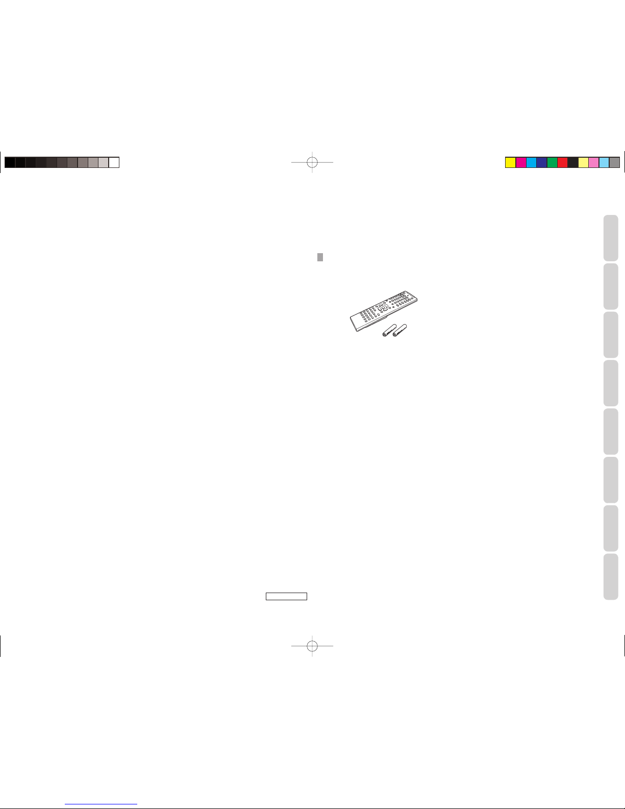
USAGE OF REMOTE CONTROLLER ........................... 3
NAMES AND FUNCTIONS............................4
FRONT PANEL................................................................ 4
FL DISPLAY AND INDICATOR..................................... 5
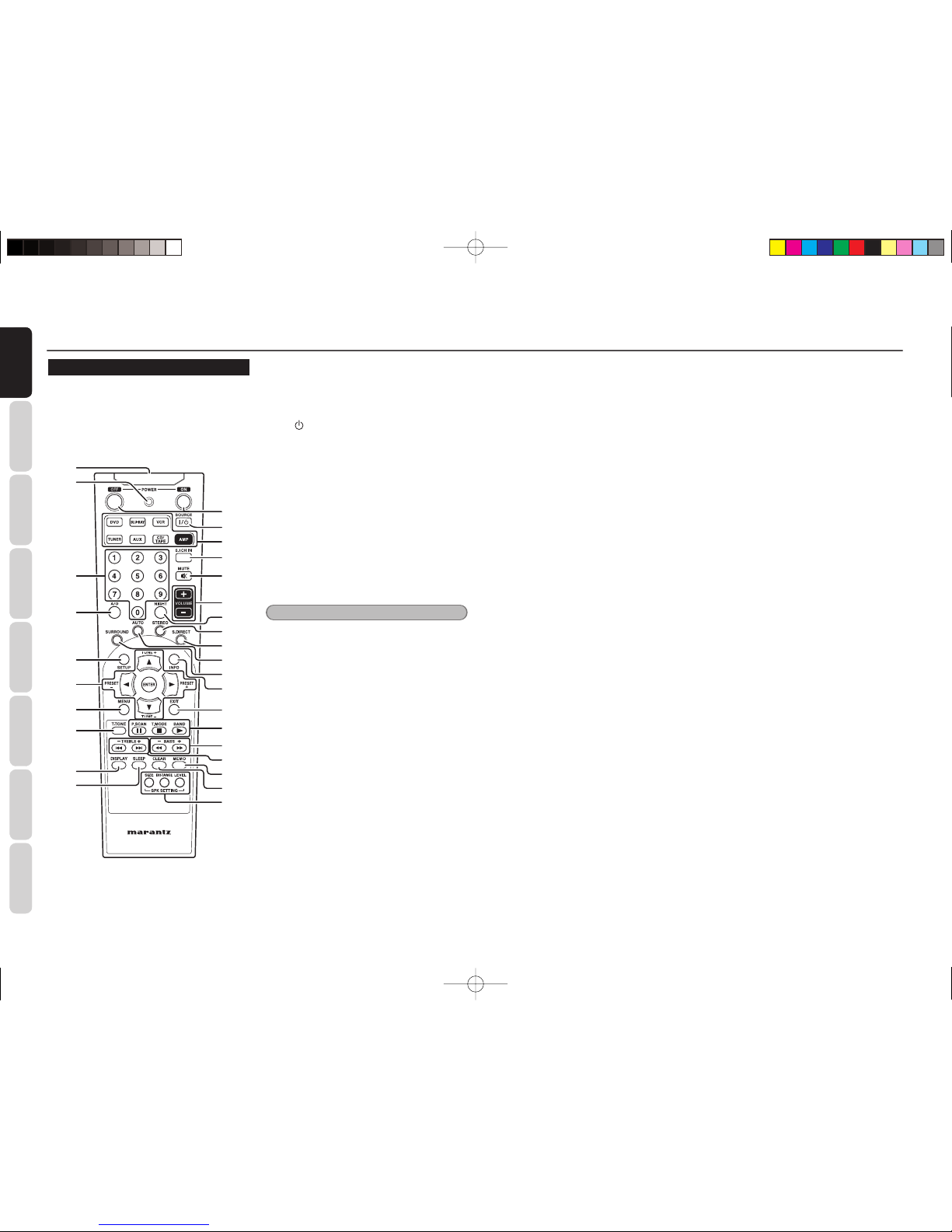
REMOTE CONTROLLER................................................ 6
REAR PANEL .................................................................. 7
BASIC CONNECTIONS ..................................8
SPEAKER PLACEMENT ............................................... 8
CONNECTING SPEAKERS........................................... 8
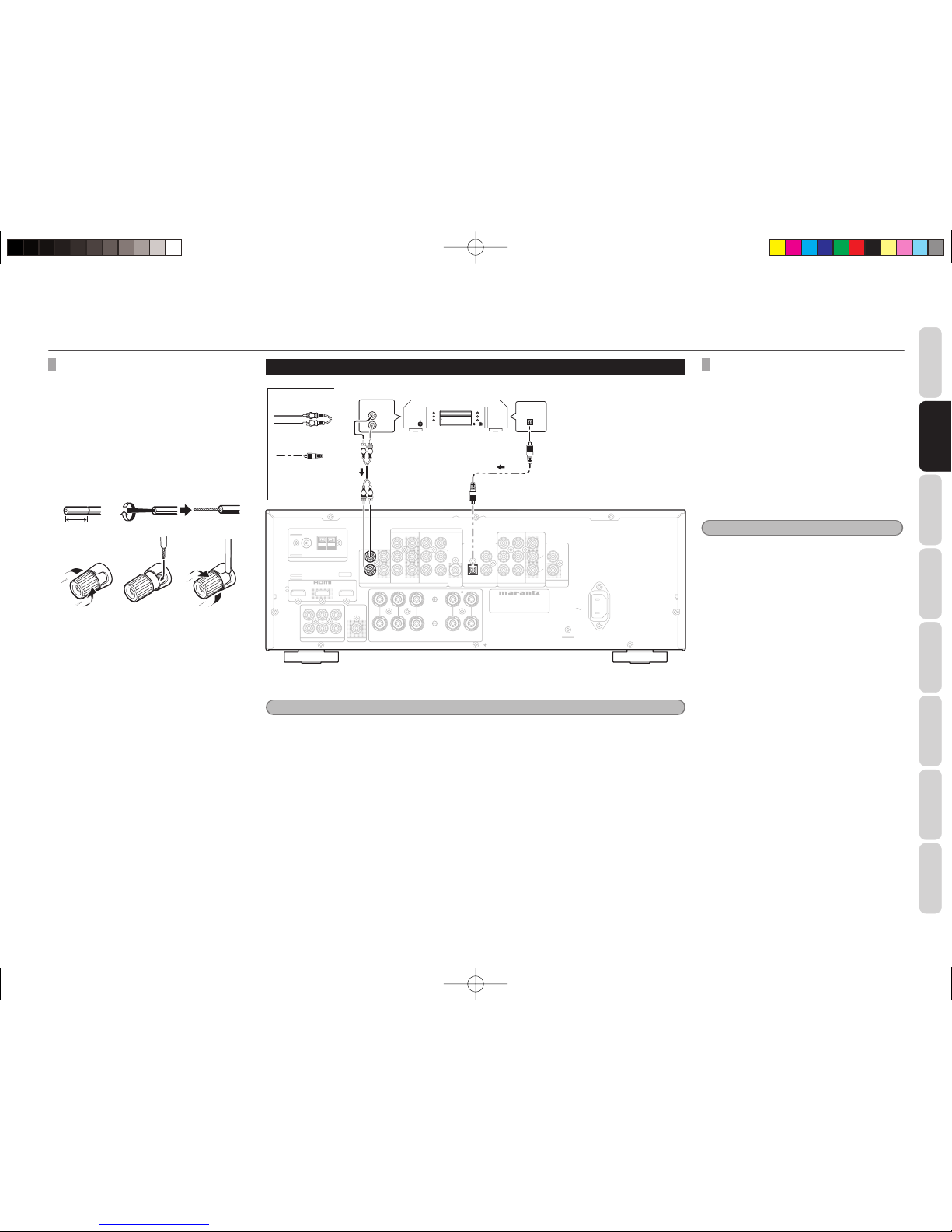
CONNECTING AUDIO COMPONENTS ..................... 9
CONNECTING VIDEO COMPONENTS .................... 10
CONNECTING HDMI COMPONENTS ..................... 11
CONNECTING THE ANTENNAS............................... 12
CONNECTING OF AC POWER CABLE..................... 12
AMP OPERATION........................................................ 12
TUNER OPERATION.................................................... 13
REMOTE CONTROLLER OPERATION ...................... 14
ADVANCED CONNECTIONS.......................15
CONNECTING MULTI CHANNEL AUDIO
COMPONENT............................................................... 15
CONNECTING THE REMOTE CONTROL JACKS ... 15
SETUP .............................................................16
SPEAKER SETUP......................................................... 16
ADVANCED OPERATION.............................19
AMP OPERATION........................................................ 19
TUNER OPERATION (PRESET MEMORY)............... 20
REMOTE CONTROLLER OPERATION ...................... 22
TROUBLESHOOTING....................................23
GENERAL ...................................................................... 23
SURROUND.................................................................. 24
TUNER........................................................................... 24
VIDEO ............................................................................ 24
HDMI ............................................................................. 25
FRONT KEY (BUTTON) LOCK .................................... 25
GENERAL MALFUNCTION ........................................ 25
HOW TO RESET THE UNIT ........................................ 25
OTHERS ..........................................................26
SURROUND MODE ..................................................... 26
DESCRIPTION.............................................................. 28
SPECIFICATIONS ........................................................ 28
DIMENSIONS .............................................................. 29
COPYRIGHT.................................................................. 29
CLEANING OF EQUIPMENT EXTERNAL SURFACES
... 29
REPAIRS........................................................................ 29
SR3053S01ENG.indd2SR3053S01ENG.indd2 09.4.2210:56:03AM09.4.2210:56:03AM

NAMES AND
FUNCTIONS
3
BASIC
CONNECTIONS
BASIC
OPERATION
ADVANCED
CONNECTIONS
SETUP
ADVANCED
OPERATION
TROUBLESHOOTING
OTHERS
BEFORE USE
EQUIPMENT MAINS WORKING
SETTING
Your Marantz product has been prepared to comply
with the household power and safety requirements
that exist in your area.
This unit can be powered by 230V AC only.
DO NOT LOCATE IN THE
FOLLOWING PLACES
To ensure long-lasting use, do not locate the unit
where:
• Exposed to direct sunlight.
• Near to sources of heat such as heaters.
• Highly humid or poorly ventilated.
• Dusty.
• Subjected to mechanical vibrations.
• On wobbly, inclined or otherwise unstable
surfaces
• Near windows where there is a chance of
exposure to rain, etc.
• On top of an amplifier or other component which
dissipates a great deal of heat
To ensure proper heat radiation, ensure the below
clearance from walls and other equipment.
Left 0.2 m (8 in)
or more
Right 0.2 m
(8 in) or more
Above 0.2 m
(8 in) or more
Rear 0.2 m (8 in) or more
KEEP OBJECTS OFF
Keep objects off the unit. Blocking the vent can
result in accident and damage.
DO NOT TOUCH HOT AREAS,
ESPECIALLY AROUND THE “HOT
SURFACE MARK” DURING AND
IMMEDIATELY AFTER USE
During and immediately after use, this product is
hot in areas other than the controls and rear panel
connection jacks. Do not touch hot areas, especially
around the “hot surface mark” and the top panel.
Contact with hot areas can cause burns.
USAGE OF REMOTE CONTROLLER
LOADING BATTERIES
Before using the remote controller for the first time,
load the batteries in the remote controller. The
batteries provided are used to verify the operations
of the remote controller only.
1. Remove the battery cover.
2. Paying close attention to polarity indicators
(ªplus and ·minus), be sure to insert
batteries correctly and as indicated.
3. Return the battery cover to its original
position.
3
2
1
CAUTIONS ON HANDLING BATTERIES
Misusing batteries can lead to fire, injury or soiling
of surrounding area as a result of leakage, rupture
or corrosion.
Carefully read the following precautions before
using batteries.
• Insert the batteries while ensuring that their
ªand ·poles are properly aligned with
the corresponding markings on the remote
controller.
• Batteries of the same size and shape may have
different voltages. Do not use any battery except
the type indicated. Do not use old and new
batteries together, and do not use different types
of batteries together.
• Do not recharge batteries.
• Keep batteries out of the reach of children. Seek
medical attention if accidentally ingested.
• Do not carry or store batteries together with
metal ball point pens, necklaces, coins, hair pins,
etc.
• If you will not be using the remote controller for
an extended time (1 month or more), remove the
batteries to prevent leakage. If batteries leak, do
not touch the fluid with bare hands. Wipe away
any fluid in the case and put in new batteries.
When doing so, handle with care, because fluid
on skin or clothing presents a burn risk. If you
accidentally get fluid on your skin, immediately
wash with water and seek medical attention.
• Do not heat or take apart batteries or put them in
flame or water.
• When disposing of used batteries, please
comply with governmental regulations or
environmental public instruction’s rules that
apply in your country or area.
• Do not expose the batteries to excessive heat
such as direct sunlight, fire or the like.
REMOTE CONTROL
Operate the remote controller within a distance of
approx. 5m from the infrared receptor window on
the front of the unit.
Approx. 5m (16.4 ft)
Remote controller
Caution
• Do not allow direct sunlight, an inverter
fluorescent light or other strong source of light to
shine onto the playerʼs infrared receptor window.
Otherwise, the operation of the remote controller
may be disabled.
• Bear in mind that operating the remote controller
may cause other devices operated by infrared
rays to be operated by mistake.
• The remote controller cannot be operated if the
space between the controller and the playerʼs
infrared receptor window is obstructed.
• Do not place any objects on top of the remote
controller.
Doing so may cause one or more buttons to be
held down which will cause the batteries to run
down.
SR3053S01ENG.indd3SR3053S01ENG.indd3 09.4.2111:46:50AM09.4.2111:46:50AM

NAMES AND
FUNCTIONS
4
BASIC
CONNECTIONS BASIC
OPERATION ADVANCED
CONNECTIONS SETUP ADVANCED
OPERATION
TROUBLESHOOTING
OTHERS
NAMES AND
FUNCTIONS
NAMES AND FUNCTIONS
FRONT PANEL
q w !3e t y !0 !1r u i o !2
!
4
!
5
!
6
!
7
qPOWER ON/OFF button, STANDBY
indicator
Press the button to turn the power ON, and press
again to turn it OFF. If the POWER switch is in the
ON position, the power of this unit can be turned
ON/OFF by pressing the POWER button on the
remote controller.
When this unit is in the standby mode with the
POWER switch set to the ON position, pressing the
ENTER button also allows to turn the power on.
The STANDBY indicator lights up when this unit
is the standby mode (power OFF) by the remote
controller.
wINPUT SELECTOR knob
This knob is used to select the input sources. (See
page 12)
eSURROUND MODE button
Press this button to select the surround mode.
rAUTO button
Press this button to select the AUTO mode from the
surround modes. When this mode is selected, the
unit determines the surround mode corresponding
to a digital input signal automatically.
tS.DIRECT button
When this button is pressed, the audio signal will
bypass the tone control circuit to provide the pure
sound quality.
In the source direct mode, the tone control circuitry
and bass management are bypassed.
Notes
• The surround mode is automatically switched to
AUTO when the source direct function is turned
on.
•
Additionally, speakers for which a “SMALL”
speaker configuration is chosen will be automatically
changed to “LARGE.”
yDISPLAY button
Press this button to change the FL display mode.
(See page 19)
uMENU button
Press this button to enter the SETUP MAIN
MENU.
iEXIT button
Press this button to exit from the SETUP MAIN
MENU.
oBAND button
Press this button to switch between FM and AM in
the TUNER mode.
!0 T.MODE button
Press this button to select the auto stereo mode or
mono mode when the FM band is selected.
(See page 13)
!1 MEMORY button
Press this button to enter the tuner preset memory
numbers or station names. (See page 20)
!2 CLEAR button
Press this button to cancel the station-memory
setting mode or preset scan tuning. (See page 21)
!3 VOLUME control knob
This knob is used to adjust the overall sound level.
Turning the control clockwise increases the sound
level. (See page 13)
!4 INFRARED receiving sensor area
This area receives infrared signals for the remote
control.
!5 Cursor (1, 2, 3, 4) / ENTER button
Press these buttons to operate the SETUP MAIN
MENU and TUNER function.
!6 AUX INPUT jack
This auxiliary analog/audio input jacks accept the
connections of a MP-3 player, game etc.
!7 PHONES jack
This jack may be used to listen to the unit’s output
through a pair of headphones. Be certain that the
headphones have a standard 1 / 4” stereo phono
plug.
SR3053S01ENG.indd4SR3053S01ENG.indd4 09.4.2111:46:50AM09.4.2111:46:50AM

NAMES AND
FUNCTIONS
5
BASIC
CONNECTIONS
BASIC
OPERATION
ADVANCED
CONNECTIONS
SETUP
ADVANCED
OPERATION
TROUBLESHOOTING
OTHERS NAMES AND
FUNCTIONS
NAMES AND FUNCTIONS
FL DISPLAY AND INDICATOR
P.SCAN ST Tuned PRESET
PROG.
MUTE
dB
kHz
MHz
AUTO VIRTUAL ES EX PL PCMD DIGITAL ANALOG SLEEP
L C R
SL
SW
SR
a s d f hg j
a¡0¡1¡5¡6 ¡2 kl¡4 ¡3
aSLEEP timer indicator
This indicator is illuminated when the sleep timer
function is in use.
sP.SCAN indicator
This indicator is illuminated when the P.SCAN mode
is active.
dTUNER’s indicators
ST(Stereo) : This indicator illuminates when an
FM station is being tuned into stereo
condition.
Tuned : This indicator illuminates when the
tuner receives a sufficiently strong
radio signal.
fPRESET indicator
This indicator is illuminated when a PRESET mode
has been selected.
gdB indicator
This indicator is illuminated when the Tone Control
is active.
hPROG indicator
This indicator is illuminated when the PRESET
MEMORY mode is active.
jOUTPUT SIGNAL CHANNEL
STATUS indicators
These indicators display the channels that are
output signal.
If the output signal is 2 channel, “L” and “R” will
be illuminated.
kMUTE indicator
This indicator is illuminated when the MUTE is
active.
lkHz/MHz indicators
These indicators are illuminated when the TUNER
FM or AM are active.
¡0 ANALOG indicator
This indicator is illuminated when an analog input
source has been selected.
¡1 DIGITAL indicator
This indicator is illuminated when a digital input has
been selected.
¡2 Main Information Display Area
This area shows messages relating to the status,
input source, surround mode, tuner, volume level or
other aspects of unit’s operation.
¡3 2PL II indicator
This indicator is illuminate to show the DOLBY Pro-
Logic and Pro-Logic II decording mode.
¡4 SIGNAL FORMAT indicators
PCM
This indicator is illuminated when the input signal is
PCM (pulse code modulation).
EX
This indicator is illuminated when a Dolby Digital EX
signal is input.
2D
This indicator is illuminated when a Dolby Digital
signal is input.
ES
This indicator is illuminated when a DTS ES signal
is input.
This indicator is illuminated when a DTS signal is
input.
¡5 VIRTUAL indicator
This indicator is illuminate to shown the VIRTUAL
surround mode.
¡6 AUTO indicator
This indicator is illuminated when a AUTO surround
mode has been selected.
SR3053S01ENG.indd5SR3053S01ENG.indd5 09.4.2111:46:50AM09.4.2111:46:50AM

NAMES AND
FUNCTIONS
6
BASIC
CONNECTIONS BASIC
OPERATION ADVANCED
CONNECTIONS SETUP ADVANCED
OPERATION
TROUBLESHOOTING
OTHERS
NAMES AND
FUNCTIONS
NAMES AND FUNCTIONS
zPOWER ON and OFF buttons
(When AMP mode is selected)
These buttons are used to turn the unit on or off.
x
I
/ SOURCE button
This button is used to turn a specific source (such
as a DVD player) on or off independently from the
rest of the system.
cSOURCE buttons
These buttons are used to switch the source of your
A/V Receiver. To change the A/V Receiver source,
press this button twice within two seconds. The
signal is sent when it is pressed the second time.
Each time a source button is pressed, the control
mode of this remote controller is changed to the
source which was pressed.
This remote controller can control 6 types of
Marantz AV equipment.
Notes
• Select the AMP as the source to use this remote
controller with the unit.
v5.1 CH IN button
Press when selecting or canceling 5.1CH input.
bMUTE button
This button is used to mute the audio for the
amplifier.
nVOLUME +/– buttons
These buttons are used to adjust the volume for
the amplifier.
mNIGHT button
Pressing this button prevents the Dolby Digital
signal from playback at a loud voice.
,STEREO button
This button is used to select STEREO mode.
.S.DIRECT button
This button is used to select SOURCE DIRECT
mode.
⁄0 AUTO button
This button is used to select auto surround.
⁄1 SURROUND button
Each press of this button will switch among
Surround modes.
⁄2 INFO button
This button is used to display the INFORMATION for
DVD and other device.
⁄3 EXIT button
(When AMP mode is selected)
This button is used to cancel setting in the setup
menu.
⁄4 CONTROL buttons
These buttons are used when operating PLAY,
STOP, PAUSE and other commands of a source.
(When TUNER mode is selected)
BAND button
This button is used to select a radio band.
T.MODE button
This button is used to select auto stereo mode or
mono mode when the FM band is selected.
P.SCAN button
This button is used to start preset scan.
⁄5 BASS +/– buttons
(When AMP mode is selected)
These buttons are used to adjust the level of low
frequency sound.
⁄6 TREBLE +/– buttons
(When AMP mode is selected)
These buttons are used to adjust the level of high
frequency sound.
⁄7 MEMO button
(When tuner mode is selected)
This button is used to store the setting of preset
channel and others.
⁄8 CLEAR button
This button is used to erase the memory or program
of a source include the Tuner mode.
⁄9 SPK SETTING buttons
LEVEL button
This button is used to call up SPK LEVEL.
DISTANCE button
This button is used to call up SPK DISTANCE.
SIZE button
This button is used to call up SPK SIZE.
¤0 SLEEP button
This button is used for setting the sleep timer.
¤1 DISPLAY button
(When AMP mode is selected)
This button is used to selects the display mode for
the front display of the unit.
¤2 T.TONE button
This button is used to enter the test tone menu.
¤3 MENU button
(When AMP mode is selected)
This button is used to call up the SETUP MAIN
MENU of the unit.
REMOTE CONTROLLER
The provided remote controller is a system remote
controller. The POWER button, numeric buttons
and control buttons are used in common across
different input source components.
The input source controlled with the remote
controller changes when one of the input selector
buttons is pressed.
z
x
c
v
¤0
¤1
¤2
¤3
¤4
¤5
¤6
¤7
¤8
¤9
b
⁄3
⁄4
n
⁄0
⁄1
⁄2
.
,
m
⁄5
⁄6
⁄7
⁄8
⁄9
SR3053S01ENG.indd6SR3053S01ENG.indd6 09.4.2111:46:50AM09.4.2111:46:50AM

NAMES AND
FUNCTIONS
7
BASIC
CONNECTIONS
BASIC
OPERATION
ADVANCED
CONNECTIONS
SETUP
ADVANCED
OPERATION
TROUBLESHOOTING
OTHERS NAMES AND
FUNCTIONS
¤4 1, 2, 3, 4(CURSOR) / ENTER
buttons
These buttons are used when controlling the cursor
of the unit, DVD or other AV equipment.
(When Tuner mode is selected)
PRESET +/ PRESET - buttons
Used to select a preset station up and down.
TUNE 3/TUNE 4buttons
Used to tune a frequency station up and down.
¤5 SETUP button
This button is used to setup for DVD and other
device.
¤6 A/D button
This button is used to switch between the analog
and digital inputs.
¤7 Numeric buttons
These buttons are used to switch between 0 to 9 of
the source components.
If the source is set to the amplifier, these buttons
are used to perform operations.
¤8 SEND indicator
Indicates when the remote controller is transmitting
a signal.
¤9 Infrared Transmitter
This transmitter emits infrared light. Press the
buttons while pointing the transmitter towards the
infrared receiver window of the unit or other AV
equipment.
NAMES AND FUNCTIONS
REAR PANEL
MODEL NO. SR3053
MODEL NO . SR3053
AC IN
AC IN
FM
FM
(
(
75
75
Ω
Ω
)
)
GND
GND
AM
AM
ANTENNA
ANTENNA
DVD
DVD
L
L
SL
SL
C
C
R
R
L
L
R
R
L
L
SUB
SUB
WOOFER
WOOFER
R
R
SR
SR
5.1CH INPUT
5.1CH INPUT
PRE OUT
PRE OUT
SW
SW
SURROUND
SURROUND
FRONT
FRONT
MONITOR OUT
MONITOR OUT
BLU-RAY
BLU-RAY
VIDEO
VIDEO
OUT
OUT
IN
IN
L
L
R
R
Y
Y
VCR
VCR
OUT
OUT
DVD
DVD
IN
IN
BLU-RAY
BLU-RAY
VCR
VCR
DVD
DVD
BLU-RAY
BLU-RAY
IN
IN
MONITOR
MONITOR
OUT
OUT
IN
IN
DVD
DVD
BLU-RAY
BLU-RAY
OUT
OUT
REMOTE
REMOTE
CONTROL
CONTROL
ANALOG AUDIO
ANALOG AUDIO
DIGITALAUDIO IN
DIGITALAUDIO IN
IN
IN
COMPONENT VIDEO
COMPONENT VIDEO
MONITOR
MONITOR
OUT
OUT
P
P
B
B
C
C
B
B
P
P
R
R
C
C
R
R
SPEAKER SYSTEMS : 6-8 OHMS
CENTER
CENTER
BLU-RAY
BLU-RAY
CD
CD
COAXIAL
COAXIAL
OPTICAL
OPTICAL
DVD
DVD
CD
CD
/
/
TAPE
TAPE
q w e r t u
io!1 !0!2
y
qANTENNA terminals
FM
Connect an external FM antenna with a coaxial
cable, or a cable network FM source.
AM
Connect the supplied AM loop antenna. Use the
terminals marked “AM” and “GND”. The supplied
AM loop antenna will provide good AM reception in
most areas. Position the loop antenna until you hear
the best reception.
wAUDIO IN/OUT terminals
(CD/TAPE, VCR, DVD, BLU-RAY)
These are the analog audio inputs and outputs.
There are 4 audio inputs (3 of which are linked
to video inputs) and 2 audio outputs (1 of which
are linked to video outputs). The audio jacks are
nominally labeled for cassette tape decks, compact
disc players, DVD players and etc.... The audio
inputs and outputs require RCA-type connectors.
eVIDEO IN/OUT terminals
(VCR, DVD, BLU-RAY)
These are the video inputs and outputs. There are
3 video inputs and 1 video outputs configurations.
Connect VCRs, DVD players, and Blu-ray disc
players to the video inputs.
The 1 video output channels can be used to be
connected to video tape recorders for making
recordings.
rMONITOR OUT terminal
Connect to TV composite input.
tDIGITAL IN terminal
These are the digital audio inputs.
This unit has 2 coaxial digital inputs and 1 optical
digital input.
The inputs accept digital audio signals from a BLU-
RAY, DVD, or CD source component.
yCOMPONENT VIDEO terminals
If your DVD player or other device has component
video connectors, be sure to connect them to these
component video connectors on the unit. This unit
has 2 component video input connectors to obtain
the color information (Y, PB/CB, PR/CR) directly from the
recorded DVD signal or other video component and
one component video output connector to output it
directly into the matrix decoder of the display device.
By sending the pure DVD component video signal
directly, the DVD signal forgoes the extra processing
that normally would degrade the image. The result
is vastly increased image quality, with incredibly life
like colors and crisp detail.
uREMOTE CONTROL IN/OUT
terminals
Connect to a Marantz component equipped with
remote control (RC-5) terminals.
iAC INLET
Plug the supplied power cable into this AC INLET
and then into the power outlet on the wall.
This unit can be powered by 230V AC only.
oSPEAKER SYSTEMS terminals
5 terminals are provided for the front left, front right,
front center, surround left, surround right speakers.
!0 SUB WOOFER PREOUT terminal
Connect this jack to the line level input of a powered
subwoofer. If an external subwoofer amplifier is used,
connect this jack to the subwoofer amplifier input. If
you are using two subwoofers, either powered or
with a 2 channel subwoofer amplifier, connect a “Y”
connector to the subwoofer output jack and run one
cable from it to each subwoofer amplifier.
!1 5.1 CH INPUT terminals
By connecting a DVD Audio player, Super Audio CD
multichannel player, or other components that has a
multichannel port, you can playback the audio with
5.1 channel outputs.
!2 HDMI terminals
This unit has 2 HDMI inputs and 1 HDMI output.
SR3053S01ENG.indd7SR3053S01ENG.indd7 09.4.2111:46:50AM09.4.2111:46:50AM

NAMES AND
FUNCTIONS
8
BASIC
CONNECTIONS BASIC
OPERATION ADVANCED
CONNECTIONS SETUP ADVANCED
OPERATION
TROUBLESHOOTING
OTHERS
BASIC
CONNECTIONS
BASIC CONNECTIONS
SPEAKER PLACEMENT
The ideal surround speaker system for this unit is 5-speaker systems, using front left and right speakers, a
center speaker, surround left and right speakers and a subwoofer.
For best results we recommend that all front speakers be of the same type, with identical or similar driver
units. This will deliver smooth pans across the front sound stage as the action moves from side to side.
Your center channel speaker is very important as over 80% of the dialog from a typical motion picture
emanates from the center channel.
It should possess similar sonic characteristics to the main speakers. Surround channel speakers need not be
identical to the front channel speakers, but they should be of high quality.
One of the benefits of both Dolby Digital and DTS is that surround channels are discrete full range, while they
were frequency limited in earlier “Pro Logic’ type systems.
Bass effects are an important part of home theater. For optimal enjoyment a subwoofer should be used as
it is optimized for low frequency reproduction. If you have full range front speakers, however, they may be
used in place of a subwoofer with proper setting of the switches in the menu system.
Front Right
Front Left
Front
Center
Surround
Left
Surround
Right
Subwoofer
FRONT LEFT AND RIGHT SPEAKERS
We recommend to set the front L and R speakers
with 45-60 degrees from the listening position.
CENTER SPEAKER
Align the front line of the center speaker with the
front L/R speakers. Or place the center speaker a
little backward from the line.
SURROUND LEFT AND RIGHT SPEAKERS
When this unit is used in surround operation, the
preferred location for surround speakers is on the
side walls of the room, at or slightly behind the
listening position.
The center of the center speaker should face the
center of the room.
SUBWOOFER
We recommend using a sub-woofer to have maximum
bass effect. As the subwoofer only handles low
frequencies, you can place it any where in the room.
HEIGHT OF THE SPEAKER UNITS
FRONT LEFT AND RIGHT SPEAKERS,
AND A CENTER SPEAKER
Align the tweeters and mid-range drivers on the
three front speakers at the same height, as best
as possible.
Note
Use magnetically-shielded speakers for front left,
right and the center speakers when the speakers are
installed near the TV.
SURROUND LEFT AND RIGHT SPEAKERS
Place the surround left, right higher than your ears
by about 70cm – 1m. Also place the speakers at the
same height, as best as possible.
70cm
1m
CONNECTING SPEAKERS
• Be sure to use speakers with the specified impedance as shown on the rear panel of this unit.
• When the subwoofer you are connecting is a powered subwoofer (i.e., has a built-in amp), connect it to
the PRE OUT subwoofer jack.
MODEL NO. SR3053
MODEL NO . SR3053
AC IN
AC IN
FM
FM
(
(
75
75
Ω
Ω
)
)
GND
GND
AM
AM
ANTENNA
ANTENNA
DVD
DVD
L
L
SL
SL
C
C
R
R
L
L
R
R
L
L
SUB
SUB
WOOFER
WOOFER
R
R
SR
SR
5.1CH INPUT
5.1CH INPUT
PRE OUT
PRE OUT
SW
SW
SURROUND
SURROUND
FRONT
FRONT
MONITOR OUT
MONITOR OUT
BLU-RAY
BLU-RAY
VIDEO
VIDEO
OUT
OUT
IN
IN
L
L
R
R
Y
Y
VCR
VCR
OUT
OUT
DVD
DVD
IN
IN
BLU-RAY
BLU-RAY
VCR
VCR
DVD
DVD
BLU-RAY
BLU-RAY
IN
IN
MONITOR
MONITOR
OUT
OUT
IN
IN
DVD
DVD
BLU-RAY
BLU-RAY
OUT
OUT
REMOTE
REMOTE
CONTROL
CONTROL
ANALOG AUDIO
ANALOG AUDIO
DIGITALAUDIO IN
DIGITALAUDIO IN
IN
IN
COMPONENT VIDEO
COMPONENT VIDEO
MONITOR
MONITOR
OUT
OUT
P
P
B
B
C
C
B
B
P
P
R
R
C
C
R
R
SPEAKER SYSTEMS : 6-8 OHMS
CENTER
CENTER
BLU-RAY
BLU-RAY
CD
CD
COAXIAL
COAXIAL
OPTICAL
OPTICAL
DVD
DVD
CD
CD
/
/
TAPE
TAPE
R
R
L
L
R
R
L
L
SUB
SUB
WOOFER
WOOFER
PRE OUT
PRE OUT
SURROUND
SURROUND
FRONT
FRONT
SPEAKER SYSTEMS : 6-8 OHMS
CENTER
CENTER
Right Left Right Left
Surround Front
CenterPowered
subwoofer
Note
• To prevent damage to circuitry, do not let the bare speaker wires touch each other and do not let them touch any
metal part of this unit.
• Do not touch the speaker terminals when the power is on. It may cause you to receive an electric shocks.
• Do not connect more than one speaker cable to one speaker terminal. Doing so may damage this unit.
• Be sure to connect the positive and negative cables for the speaker properly. If they are miss-connected, the
signal phase will be reversed and the signal quality will be corrupted.
SR3053S01ENG.indd8SR3053S01ENG.indd8 09.4.2111:46:51AM09.4.2111:46:51AM

NAMES AND
FUNCTIONS
9
BASIC
CONNECTIONS
BASIC
OPERATION
ADVANCED
CONNECTIONS
SETUP
ADVANCED
OPERATION
TROUBLESHOOTING
OTHERS BASIC
CONNECTIONS
CONNECTING SPEAKER WIRE
1. Strip away approx. 10 mm (3/8 inch) of wire
insulation.
2. Twist the bared wire ends tight, to prevent
short circuits.
3.
Loosen the knob by turning it counterclockwise.
4. Insert the bare part of the wire into the hole
in side of each terminal.
5. Tighten the knob by turning it clockwise to
secure the wire.
1. 2.
3. 4. 5.
10 mm
(3/8 inch)
BASIC CONNECTIONS
CONNECTING AUDIO COMPONENTS
MODEL NO. SR3053
MODEL NO . SR3053
AC IN
AC IN
FM
FM
(
(
75
75
Ω
Ω
)
)
GND
GND
AM
AM
ANTENNA
ANTENNA
DVD
DVD
L
L
SL
SL
C
C
R
R
L
L
R
R
L
L
SUB
SUB
WOOFER
WOOFER
R
R
SR
SR
5.1CH INPUT
5.1CH INPUT
PRE OUT
PRE OUT
SW
SW
SURROUND
SURROUND
FRONT
FRONT
MONITOR OUT
MONITOR OUT
BLU-RAY
BLU-RAY
VIDEO
VIDEO
OUT
OUT
IN
IN
L
L
R
R
Y
Y
VCR
VCR
OUT
OUT
DVD
DVD
IN
IN
BLU-RAY
BLU-RAY
VCR
VCR
DVD
DVD
BLU-RAY
BLU-RAY
IN
IN
MONITOR
MONITOR
OUT
OUT
IN
IN
DVD
DVD
BLU-RAY
BLU-RAY
OUT
OUT
REMOTE
REMOTE
CONTROL
CONTROL
ANALOG AUDIO
ANALOG AUDIO
DIGITALAUDIO IN
DIGITALAUDIO IN
IN
IN
COMPONENT VIDEO
COMPONENT VIDEO
MONITOR
MONITOR
OUT
OUT
P
P
B
B
C
C
B
B
P
P
R
R
C
C
R
R
SPEAKER SYSTEMS : 6-8 OHMS
CENTER
CENTER
BLU-RAY
BLU-RAY
CD
CD
COAXIAL
COAXIAL
OPTICAL
OPTICAL
DVD
DVD
CD
CD
/
/
TAPE
TAPE
IN
IN
L
L
R
R
OPTICAL
OPTICAL
ANALOG AUDIO
ANALOG AUDIO
DIGITALAUDIO IN
DIGITALAUDIO IN
CD
CD
CD
CD
/
/
TAPE
TAPE
OUT
L
R
L R
R L
DIGITAL
OUTPUT
L R
CD Player
Analog Audio
Digital Audio (optical)
When using a tape deck, connect Analog Audio OUT/IN only.
Notes
• Do not connect this unit and other components to mains power until all connections between components have
been completed.
• Insert all plugs and connectors securely. Incomplete connections may make noise.
• Be sure to connect the left and right channels properly.
Red connectors are for the R (right) channel, and white connectors are for the L (left) channel.
• Be sure to connect input and output properly.
• Refer to the instructions for each component that is connected to this unit.
• Do not tie the connected cable into a bundle with the power supply cord or speaker cables. Doing so may cause
noise.
CONNECTING DIGITAL AUDIO
COMPONENTS
• There are 3 digital inputs, 2 coaxial jacks and
1 optical jacks, on the rear panel. You can use
these jacks to input PCM, Dolby Digital and DTS
bitstream signals from a Blu-ray, DVD, and CD.
• Refer to the instructions for each component. To
setup the digital audio format of Blu-ray player, or
other digital source’s connected to digital input
jacks.
• Use fiber optical cables (optical) for CD, input
jacks. Use 75 ohms coaxial cables (for digital
audio) for Blu-ray, DVD, input jacks.
Notes
• There is no Dolby Digital RF input jack. Please
use an external RF demodulator Dolby Digital
decoder when connecting the Dolby Digital RF
output jack of the video disc player to the digital
input jack.
• The digital signal jacks on this unit conform to
the EIA standard. If you use a cable that does
not conform to this standard, this unit may not
function properly.
• Each type of audio jack works independently.
Signals input through the digital and analog jacks
are output through the corresponding digital and
analog jacks, respectively.
SR3053S01ENG.indd9SR3053S01ENG.indd9 09.4.2111:46:51AM09.4.2111:46:51AM

NAMES AND
FUNCTIONS
10
BASIC
CONNECTIONS BASIC
OPERATION ADVANCED
CONNECTIONS SETUP ADVANCED
OPERATION
TROUBLESHOOTING
OTHERS
BASIC
CONNECTIONS
BASIC CONNECTIONS
CONNECTING VIDEO COMPONENTS VIDEO, COMPONENT JACKS
There are 2 types of video jacks on the rear panel.
VIDEO JACK
The video signal for the VIDEO jacks is the conventional composite video signal.
COMPONENT JACK
Make component video connections to a TV or monitor with component inputs to produce higher quality
video images. Use a component video cable or 3 video cable to connect the component video out jacks on
the unit to the monitor.
Notes
• Be sure to connect the left and right audio channels properly.
Red connectors are for the R (right) channel, and white connectors are the for L (left) channel.
• Be sure to connect the inputs and outputs of the video signals properly.
• You may need to setup the digital audio output format of your DVD player, or other digital source components.
Refer to the instructions of the each component connected to the digital input jacks.
• There is no Dolby Digital RF input jack. Use an external RF demodulator with a Dolby Digital decoder to
connect the Dolby Digital RF output jack of the DVD player to the digital input jack on this unit.
MODEL NO. SR3053
MODEL NO . SR3053
AC IN
AC IN
FM
FM
(
(
75
75
Ω
Ω
)
)
GND
GND
AM
AM
ANTENNA
ANTENNA
DVD
DVD
L
L
SL
SL
C
C
R
R
L
L
R
R
L
L
SUB
SUB
WOOFER
WOOFER
R
R
SR
SR
5.1CH INPUT
5.1CH INPUT
PRE OUT
PRE OUT
SW
SW
SURROUND
SURROUND
FRONT
FRONT
MONITOR OUT
MONITOR OUT
BLU-RAY
BLU-RAY
VIDEO
VIDEO
OUT
OUT
IN
IN
L
L
R
R
Y
Y
VCR
VCR
OUT
OUT
DVD
DVD
IN
IN
BLU-RAY
BLU-RAY
VCR
VCR
DVD
DVD
BLU-RAY
BLU-RAY
IN
IN
MONITOR
MONITOR
OUT
OUT
IN
IN
DVD
DVD
BLU-RAY
BLU-RAY
OUT
OUT
REMOTE
REMOTE
CONTROL
CONTROL
ANALOG AUDIO
ANALOG AUDIO
DIGITALAUDIO IN
DIGITALAUDIO IN
IN
IN
COMPONENT VIDEO
COMPONENT VIDEO
MONITOR
MONITOR
OUT
OUT
P
P
B
B
C
C
B
B
P
P
R
R
C
C
R
R
SPEAKER SYSTEMS : 6-8 OHMS
CENTER
CENTER
BLU-RAY
BLU-RAY
CD
CD
COAXIAL
COAXIAL
OPTICAL
OPTICAL
DVD
DVD
CD
CD
/
/
TAPE
TAPE
VIDEO
VIDEO
Y
Y
VCR
VCR
OUT
OUT
DVD
DVD
IN
IN
VCR
VCR
DVD
DVD
MONITOR
MONITOR
OUT
OUT
IN
IN
DVD
DVD
ANALOG AUDIO
ANALOG AUDIO
DVD
DVD
MONITOR
MONITOR
OUT
OUT
P
P
B
B
C
C
B
B
P
P
R
R
C
C
R
R
L
L
R
R
COMPONENT VIDEO
COMPONENT VIDEO
DIGITALAUDIO IN
DIGITALAUDIO IN
COAXIAL
COAXIAL
LR
AUD IO
OUT
DIGITAL
OUT
VIDEO
OUT
LR
AUDIO
OUT
AUD IO
IN
LR
VIDEO
OUT IN
L R
L R L R LR
YC
B
/
P
B
C
R
/
P
R
COMPONENT
VIDEO OUT
YC
B
/
P
B
C
R
/
P
R
COMPONENT
VIDEO IN
VIDEO
IN
L R L R
L R
DVD player Video projector
VCR
Video
Analog Audio
Digital Audio
(coaxial)
TV
SR3053S01ENG.indd10SR3053S01ENG.indd10 09.4.2111:46:51AM09.4.2111:46:51AM

NAMES AND
FUNCTIONS
11
BASIC
CONNECTIONS
BASIC
OPERATION
ADVANCED
CONNECTIONS
SETUP
ADVANCED
OPERATION
TROUBLESHOOTING
OTHERS BASIC
CONNECTIONS
BASIC CONNECTIONS
CONNECTING HDMI COMPONENTS
An HDMI cable (sold separately) is used to connect
the HDMI jack on the unit with the HDMI jack
on a Blu-ray disc player, TV, projector or other
component.
HDMI video streaming is compatible with DVI in
principle. Therefore, it is possible to connect to a TV
or monitor that has a DVI terminal using an HDMI-
DVI conversion cable or plug. When connecting to a
DVI terminal, connect the audio signal separately.
Notes
• Some HDMI components can be controlled over
the HDMI cable, but this unit cannot control other
components this way.
• When connected to a monitor (i.e., TV, projector,
etc.) that does not support HDCP, video and
audio are not output.
• DVI cables come with 24-pin and 29-pin plugs.
This unit supports 24-pin DVI-D cables; 29-pin
DVI cables cannot connect to it.
• When multiple components are connected to this
unit, turn power to unused components off to
prevent interference between them.
• Disconnecting or connecting cables with the
power on can damage the equipment. Turn the
power off before disconnecting or connecting
cables.
• If the DVD player or other device with DVI output
is connected to the unit, a separate audio cable
(optical-digital, coaxial digital or analog) is
needed for the audio signals.
• Depending on the quality of the cable used, the
HDMI signal may be affected by noise.
CONNECTING HDMI COMPONENTS
HDMI JACK
This unit has 2 HDMI inputs and one HDMI output. There is only a pass-through mode in HDMI of this unit.
This unit does not support HDMI repeater. So, the sound of HDMI audio is not output from the speaker as
this unit.
When output the sound from the Blu-ray and DVD sources that connects HDMI cable with this unit, a
separate audio cable (coax digital or analog) is needed for the audio signals.
Notes
• When the HDMI output is connected to a display monitor that does not support HDCP*, signals are not output.
To view images in HDMI, it is necessary to connect to a display that supports HDCP*.
• There may be no image output if connected to a TV or display that is not compatible with the above format.
• Refer to the instruction manual of the TV or display to be connected to the unit for detailed information
regarding the HDMI terminal.
* HDCP: High-bandwidth Digital Content Protection
MODEL NO. SR3053
MODEL NO . SR3053
AC IN
AC IN
FM
FM
(
(
75
75
Ω
Ω
)
)
GND
GND
AM
AM
ANTENNA
ANTENNA
DVD
DVD
L
L
SL
SL
C
C
R
R
L
L
R
R
L
L
SUB
SUB
WOOFER
WOOFER
R
R
SR
SR
5.1CH INPUT
5.1CH INPUT
PRE OUT
PRE OUT
SW
SW
SURROUND
SURROUND
FRONT
FRONT
MONITOR OUT
MONITOR OUT
BLU-RAY
BLU-RAY
VIDEO
VIDEO
OUT
OUT
IN
IN
L
L
R
R
Y
Y
VCR
VCR
OUT
OUT
DVD
DVD
IN
IN
BLU-RAY
BLU-RAY
VCR
VCR
DVD
DVD
BLU-RAY
BLU-RAY
IN
IN
MONITOR
MONITOR
OUT
OUT
IN
IN
DVD
DVD
BLU-RAY
BLU-RAY
OUT
OUT
REMOTE
REMOTE
CONTROL
CONTROL
ANALOG AUDIO
ANALOG AUDIO
DIGITALAUDIO IN
DIGITALAUDIO IN
IN
IN
COMPONENT VIDEO
COMPONENT VIDEO
MONITOR
MONITOR
OUT
OUT
P
P
B
B
C
C
B
B
P
P
R
R
C
C
R
R
SPEAKER SYSTEMS : 6-8 OHMS
CENTER
CENTER
BLU-RAY
BLU-RAY
CD
CD
COAXIAL
COAXIAL
OPTICAL
OPTICAL
DVD
DVD
CD
CD
/
/
TAPE
TAPE
DVD
DVD
MONITOR OUT
MONITOR OUT
BLU-RAY
BLU-RAY
DIGITALAUDIO IN
DIGITALAUDIO IN
BLU-RAY
BLU-RAY
COAXIAL
COAXIAL
DVD
DVD
HDMI
OUTPUT
STANDBY
POWERON/OFF
HDMI
OUTPUT
HDMI
INPUT
DIGITAL
OUTPUT
DIGITAL
OUTPUT
DVD player Video projector
Blu-ray disc player
SR3053S01ENG.indd11SR3053S01ENG.indd11 09.4.2111:46:52AM09.4.2111:46:52AM

NAMES AND
FUNCTIONS
12
BASIC
CONNECTIONS BASIC
OPERATION ADVANCED
CONNECTIONS SETUP ADVANCED
OPERATION
TROUBLESHOOTING
OTHERS
BASIC
CONNECTIONS BASIC
OPERATION
BASIC CONNECTIONS
CONNECTING THE ANTENNAS
CONNECTING THE SUPPLIED ANTENNAS
The supplied antennas are for indoor use only.
FM
FM
(
(
75
75
Ω
Ω
)
)
GND
GND
AM
AM
ASSEMBLING THE AM LOOP ANTENNA
Insertting the tabs into the base as shown.
CONNECTING THE AM ANTENNA CABLE
Press and hold Insert wire Release
WhiteBlack
Note
• During use, extend the FM antenna and move it in various directions until the clearest sound is received.
Fix it with push pins or similar implements in that cause the least amount of distortion.
• Set in the direction and position it to where you receive the clearest sound. Put it as far away as possible from
the unit, televisions,speaker cables and power cable.
CONNECTING AN OUTDOOR ANTENNAS
If you experience poor reception quality, an outdoor antenna may improve the quality.
Keep the antenna from noise sources (neon signes, busy roads, power lines, transformers, etc)
FM
FM
(
(
75
75
Ω
Ω
)
)
GND
GND
AM
AM
FM External
Antenna
AM Loop Antenna
Black White
Ground
AM External
Antenna
16 to 32ft (5 to 10m)
Vinyl-coated wire
Note
• Do not remove the AM loop antenna.
• Do not connect the supplied FM antenna.
• The terminal marked “GND” on this unit is not for safety grounding.
CONNECTING OF AC POWER CABLE
1. Plug the supplied AC power cable to the
AC IN socket on the rear panel of the main
unit.
AC IN
2. Plug the power cable into an AC outlet.
BASIC OPERATION
AMP OPERATION
TURNING ON THE UNIT
1. Turn the power of the equipment connected
to this unit on.
2. Press the POWER ON/OFF button on the
unit. The power of the main unit switches
on/off each time this button is pressed.
Pressing POWER OFF or SOURCE ON/OFF
after pressing the AMP button on the
remote controller causes the STANDBY
indicator on the unit to light, and the unit to
go into standby mode.
To turn the power on while in standby
mode, press the ENTER button on the unit
or the AMP button on the remote controller,
then press POWER ON or SOURCE ON/
OFF.
SELECTING AN INPUT SOURCE
Before you can listen to any input media, you must
first select the input source on the unit.
EXAMPLE : DVD
To select DVD, turn the INPUT SOURCE knob on
the front panel or press the DVD button on the
remote controller two times in a row.
After you have selected DVD, simply turn on the
DVD player and play the DVD.
• As the input source is changed, the new input
name will appear in the display, on the front-
panel.
• As the input is changed, this unit will automatically
switch to the digital input, surround mode, and
night mode status which were entered during the
configuration process for that source.
SR3053S01ENG.indd12SR3053S01ENG.indd12 09.4.2111:46:52AM09.4.2111:46:52AM

NAMES AND
FUNCTIONS
13
BASIC
CONNECTIONS
BASIC
OPERATION
ADVANCED
CONNECTIONS
SETUP
ADVANCED
OPERATION
TROUBLESHOOTING
OTHERS BASIC
OPERATION
BASIC OPERATION
• When an audio source is selected, the last video
input used remains routed to the VCR Output
and Monitor Output. This permits simultaneous
viewing and listening to different sources.
• When a Video source is selected, the video
signal for that input will be routed to the Monitor
Output jacks and will be viewable on a TV
monitor connected to the unit.
If a component video input is connected to the
DVD or BLU-RAY component inputs, it will be
routed to the Component Video Output. Make
certain that your TV is set to the proper input to
view the signal.
ADJUSTING THE MAIN VOLUME
Adjust the volume to a comfortable level using
the VOLUME control knob on the front panel or
VOLUME +/ –buttons on the remote controller.
To increase the volume, turn the VOLUME knob
clockwise or press VOLUME +button on the
remote controller, to decrease the volume, turn
counterclockwise or press VOLUME –button on
the remote controller.
Notes
• The volume can be adjusted within the range of
VOL MUTE – to 16 dB, in steps of 1 dB.
• However, when the channel level is set as described
on page 17, if the volume for any channel is set at
+1 dB or greater, the volume cannot be adjusted
up to 16 dB.
(In this case the maximum volume adjustment
range is “16 dB - Maximum value of channel
level)
ADJUSTING THE TONE (BASS & TREBLE)
CONTROL
During a listening session you may wish to adjust
the Bass and Treble Control to suit your listening
tastes or room acoustics.
USING THE REMOTE CONTROLLER
To adjust the bass effect, press BASS + or BASS
–on the remote controller.
To adjust the treble effect, press TREBLE + or
TREBLE – on the remote controller.
Note
The tone control function can work in the AUTO
Surround, Stereo, Dolby PLII and DTS mode.
TEMPORARILY TURNING OFF THE SOUND
To temporarily silence all speaker outputs such as
when interrupted by a phone call, press the MUTE
button on the remote controller.
This will interrupt the output to all speakers and the
head-phone jack, but it will not affect any recording
or dubbing that may be in progress.
When the system is muted, the display will show
“MUTE” .
Press the MUTE button again to return to normal
operation.
TUNER OPERATION
Frequency scan step for AM is selectable.
Default setup is 9 kHz step, if your country’s
standard is 10 kHz step, Press BAND button on the
remote controller more than 6 seconds. Scan step
will change.
Note
Preset memory for the tuner will clear by changing
this setup.
AUTO TUNING
2. 1.
2
.
1
.
USING THE UNIT
1. To select tuner and desired band (FM or
AM), press the BAND button on the front
panel.
2. Press the 3or 4cursor buttons on the front
panel for more than 1 second to start the
auto tuning function.
3. Automatic searching begins then stops
when a station is tuned in.
USING THE REMOTE CONTROLLER
1. To select tuner and desired band (FM or
AM), press the BAND button on the remote
controller.
2. Press the TUNE 3or 4for more than 1
second on the remote controller.
3. Automatic searching begins then stops
when a station is tuned in.
If tuning does not stop at the desired station, use to
the “Manual tuning” operation.
MANUAL TUNING
2. 1.
2
.
1
.
USING THE UNIT
1. To select tuner and desired band (FM or
AM), press the BAND button on the front
panel.
2. Press the 3or 4cursor buttons on the front
panel to select the desired station.
USING THE REMOTE CONTROLLER
1. To select tuner and desired band (FM or
AM), press the BAND button on the remote
controller.
2. Press the TUNE 3or 4on the remote
controller to tune in the desired station.
(FM) TUNING MODE (AUTO STEREO OR MONO)
The “ST” indicator is illuminated when a stereo
broadcast is tuned in.
At open frequencies, the noise is muted and the
“TUNED” and “ST” indicators are not illuminated.
If the signal is weak, it may be difficult to tune into
the station in stereo. In such a case, press the
T.MODE button on the front panel or remote
controller.
The “ST” indicator is not illuminated, if FM stereo
broadcasts are received in monaural.
To return to auto stereo mode, press the T.MODE
button or press T.MODE button on the remote
controller again.
SR3053S01ENG.indd13SR3053S01ENG.indd13 09.4.2111:46:52AM09.4.2111:46:52AM

NAMES AND
FUNCTIONS
14
BASIC
CONNECTIONS BASIC
OPERATION ADVANCED
CONNECTIONS SETUP ADVANCED
OPERATION
TROUBLESHOOTING
OTHERS
BASIC
OPERATION
REMOTE CONTROLLER OPERATION
To control the unit by your remote controller, you have to select the device AMP or TUNER by pressing the SOURCE button. Please refer below for the details in AMP and TUNER mode.
BASIC OPERATION
POWER ON Turns the SR3053 on
POWER OFF Turns the SR3053 off
SOURCE ON/OFF Turns the SR3053 on and off
AMP Selects AMP mode of remote unit
SOURCE Selects a particular source component
5.1 CH IN Selects the 5.1CH IN
MUTE Decreases the sound temporarily
VOLUME+/– Adjusts the over all sound level
A/D Switches between the analog or digital inputs
NIGHT Turns on or off NIGHT mode
SURROUND Selects the surround mode
AUTO Selects auto surround
STEREO Selects STEREO mode
S.DIRECT Selects the pure direct mode
Cursor Moves the cursor for setting in "SETUP MENU" mode
ENTER Confirms the setting in "SETUP MENU" mode
MENU Enters the "SETUP MENU"
EXIT Exits from SETUP MENU
T.TONE Enters the test tone menu
TREBLE–/+ Adjusts the tone control of high frequency sound
BASS–/+ Adjusts the tone control of low frequency sound
DISPLAY Changes the front display mode
SLEEP Sets the sleep timer function
SIZE Calls up SPK SIZE adjust.
DISTANCE Calls up SPK DISTANCE adjust.
LEVEL Calls up SPK CH LEVEL ADJUST and adjusts speaker
levels or 5.1ch input level
AMP AMP function enabled
SOURCE AMP function enabled
5.1 CH IN AMP function enabled
MUTE AMP function enabled
VOLUME+/– AMP function enabled
0-9 Inputs the numeric
A/D AMP function enabled
NIGHT AMP function enabled
SURROUND AMP function enabled
AUTO AMP function enabled
STEREO AMP function enabled
S.DIRECT AMP function enabled
TUNE 3/ 4Tunes a frequency station up and down
PRESET + 2/– 1Selects a preset station up and down
MENU AMP function enabled
EXIT AMP function enabled
T.TONE AMP function enabled
P.SCAN Starts preset scan
T.MODE Selects the auto stereo mode or mono mode
BAND Selects a radio band
TREBLE–/+ AMP function enabled
BASS–/+ AMP function enabled
DISPLAY AMP function enabled
SLEEP AMP function enabled
CLEAR Clears the inputting
MEMO Enters the tuner preset memory numbers
SIZE AMP function enabled
DISTANCE AMP function enabled
LEVEL AMP function enabled
AMP MODE TUNER MODE
SR3053S01ENG.indd14SR3053S01ENG.indd14 09.4.2111:46:53AM09.4.2111:46:53AM

NAMES AND
FUNCTIONS
15
BASIC
CONNECTIONS
BASIC
OPERATION
ADVANCED
CONNECTIONS
SETUP
ADVANCED
OPERATION
TROUBLESHOOTING
OTHERS ADVANCED
CONNECTIONS
ADVANCED CONNECTIONS
CONNECTING MULTI CHANNEL AUDIO COMPONENT
The 5.1CH INPUT jacks are for multichannel audio source such as the Super Audio CD multichannel player,
DVD audio player or external decoder.
If you use these jacks, switch on the 5.1CH INPUT and set the 5.1CH INPUT level by using the remote
controller. See page 20.
MODEL NO. SR3053
MODEL NO . SR3053
AC
AC IN
FM
FM
(
(
75
75
Ω
Ω
)
)
GND
GND
AM
AM
ANTENNA
ANTENNA
DVD
DVD
L
L
SL
SL
C
C
R
R
L
L
R
R
L
L
SUB
SUB
WOOFER
WOOFER
R
R
SR
SR
5.1CH INPUT
5.1CH INPUT
PRE OUT
PRE OUT
SW
SW
SURROUND
SURROUND
FRONT
FRONT
MONITOR OUT
MONITOR OUT
BLU-RAY
BLU-RAY
VIDEO
VIDEO
OUT
OUT
IN
IN
L
L
R
R
Y
Y
VCR
VCR
OUT
OUT
DVD
DVD
IN
IN
BLU-RAY
BLU-RAY
VCR
VCR
DVD
DVD
BLU-RAY
BLU-RAY
IN
IN
MONITOR
MONITOR
OUT
OUT
IN
IN
DVD
DVD
BLU-RAY
BLU-RAY
OUT
OUT
REMOTE
REMOTE
CONTROL
CONTROL
ANALOG AUDIO
ANALOG AUDIO
DIGITALAUDIO IN
DIGITALAUDIO IN
IN
IN
COMPONENT VIDEO
COMPONENT VIDEO
MONITOR
MONITOR
OUT
OUT
P
P
B
B
C
C
B
B
P
P
R
R
C
C
R
R
SPEAKER SYSTEMS : 6-8 OHMS
CENTER
CENTER
BLU-RAY
BLU-RAY
CD
CD
COAXIAL
COAXIAL
OPTICAL
OPTICAL
DVD
DVD
CD
CD
/
/
TAPE
TAPE
L
L
SL
SL
C
C
R
R
SR
SR
5.1CH INPUT
5.1CH INPUT
SW
SW
L
R
FRONT SURR.
SUB
WOOFER
CENTER
R L R L
RL RL
DVD Audio player
or
Super Audio CD
Multi channel player
CONNECTING THE REMOTE CONTROL JACKS
MODEL NO. SR3053
MODEL NO . SR3053
R
R
L
L
R
R
L
L
U
B
SUB
FER
WOOFER
O
UT
PRE OUT
SURROUND
SURROUND
FRONT
FRONT
VIDEO
VIDEO
OUT
OUT
IN
IN
L
L
R
R
Y
Y
VCR
VCR
OUT
OUT
DVD
DVD
IN
IN
BLU-RAY
BLU-RAY
VCR
VCR
DVD
DVD
BLU-RAY
BLU-RAY
IN
IN
MONITOR
MONITOR
OUT
OUT
IN
IN
DVD
DVD
BLU-RAY
BLU-RAY
OUT
OUT
REMOTE
REMOTE
CONTROL
CONTROL
ANALOG AUDIO
ANALOG AUDIO
DIGITALAUDIO IN
DIGITALAUDIO IN
IN
IN
COMPONENT VIDEO
COMPONENT VIDEO
MONITOR
MONITOR
OUT
OUT
P
P
B
B
C
C
B
B
P
P
R
R
C
C
R
R
SPEAKER SYSTEMS : 6-8 OHMS
CENTER
CENTER
BLU-RAY
BLU-RAY
CD
CD
COAXIAL
COAXIAL
OPTICAL
OPTICAL
DVD
DVD
CD
CD
/
/
TAPE
TAPE
OUT
OUT
REMOTE
REMOTE
CONTROL
CONTROL
IN
IN
REMOTE
CONTROL
REMOTE
CONTROL
REMOTE
CONTROL
IN
OUT
IN
OUT
IN
OUT
EXTERNAL INTERNAL EXTERNAL INTERNAL EXTERNAL INTERNAL
1
RC OUT
2
STANDBY
POWERON/OFF
Option
DVD player CD playerBlu-ray disc player
q
You can control other Marantz products through this
unit with the remote controller by connecting the
REMOTE CONTROL terminals on each unit.
The signal transmitted from the remote controller
is received by the remote sensor on this unit. Then
the signal is sent to the connected device through
this terminal. Therefore you need to aim the remote
signal only to the unit. Also, if a Marantz power
amplifier (some models excluded) is connected
to one of these terminals, the power amplifier’s,
power switch is synchronized with this unit’s power
switch.
Set the REMOTE CONTROL SWITCH on the back of
other units (not the SR3053) to “EXT”.(EXTERNAL)
to use this feature.
w
Whenever external infrared sensors or similar
devices are connected to RC-5 IN of the unit, be sure
to always disable operation of the infrared sensor on
the unit by using the following procedure.
1. Hold down the SURROUND MODE button
and MENU button on the front panel at the
same time for five seconds.
2. The setting “ENABLE” is shown on the FL
DISPLAY.
3. Press the 1or 2cursor button to change
this to “DISABLE”.
4. Press the ENTER button. Once this setting
is made, the infrared sensor on the unit is
disabled.
Note
Be sure to set to “ENABLE” when external infrared
sensors or similar devices are not connected.
Otherwise, the unit will be unable to receive remote
control commands.
5. To restore the original setting, perform
steps 1 to 4 to set to “ENABLE”.
SR3053S01ENG.indd15SR3053S01ENG.indd15 09.4.2111:46:53AM09.4.2111:46:53AM

NAMES AND
FUNCTIONS
16
BASIC
CONNECTIONS BASIC
OPERATION ADVANCED
CONNECTIONS SETUP ADVANCED
OPERATION
TROUBLESHOOTING
OTHERSSETUP
SPEAKER SETUP
After you have installed the unit, connected all the
components, and determined the speaker layout, it
is now time to perform the settings in the Speaker
Setup menu for the optimum sound acoustics for
your environment and speaker layout.
Before you perform the following settings, it is
important that you first determine the following
characteristics:
After all components are connected, initial setup
must be performed.
1.
Press the AMP button of the remote controller.
(This step is not needed when operating the
setup menus from the unit itself.)
2. Press the MENU button on the remote
controller or the unit.
3.
Select a desired sub-menu with the 3or 4
cursor buttons, and press the ENTER button
to enter. The display will change to the
selected sub-menu. You can move the each
sub-menu with the 1or 2buttons.
4. If you desire to exit from this menu system,
press the EXIT button.
3, 4, 1, 2,
ENTER
EXITMENU
3, 4, 1, 2,
ENTER
EXIT
MENU
SIZE
DISTANCE
LEVEL
SETUP
MENU
Press MENU button. ENTER button
FL Maximum
+10dB
+9dB
0dB
-9dB
-10dB
1dB interval
1dB interval
1foot (0.3m)
interval
Minimum
Maximum
30FT (9.0M)
29FT (8.7M)
2FT (0.6M)
1FT (0.3M) Minimum
CT
FR
FRNT SML
LRG
SML
LRG
NONE
SML
LRG
NONE
YES
NONE
FT
M
CNTR
SURR
SUB
UNIT
FRNT
CNTR
SURR
SUB
SR
SL
SW
Press LEVEL button on the remote controller.
ENTER button
ENTER button
3/4button 1/2button 3/4button
SPK LEVEL
SPK SIZE
SPK DIST
LEVEL
Press SIZE button on the remote controller.
1/2button 3/4button
3/4button
3/4button
SIZE
Press DISTANCE button on the remote controller.
1/2button
DISTANCE
SR3053S01ENG.indd16SR3053S01ENG.indd16 09.4.2111:46:53AM09.4.2111:46:53AM

NAMES AND
FUNCTIONS
17
BASIC
CONNECTIONS
BASIC
OPERATION
ADVANCED
CONNECTIONS
SETUP
ADVANCED
OPERATION
TROUBLESHOOTING
OTHERS SETUP
SETUP
SPK LEVEL
Here you will set the volume for each speaker so
that they are all heard by the listener at the same
level.
1. Select SPK LEVEL in SETUP MENU with 3
or 4cursor button, and press the ENTER
button.
2. To select desired channel, press the 1or 2
cursor buttons.
3. Using the 3or 4cursor buttons, adjust the
volume level of each channel.
4. After you complete this portion of the set
up, press the EXIT button.
SPK SIZE
Here, set the unit to the size of the speakers you
have.
1. Select “SPK SIZE” in SETUP MENU with 3
or 4cursor button, and press the ENTER
button.
When setting the speaker size in the SPK SIZE sub-
menu, use the guidelines given below.
LRG:
The complete frequency range for the channel you
are setting will be output from the speaker.
SML:
Frequencies of the channel you are setting lower
than approx. 100 Hz will be output from the
subwoofer.
If the Subwoofer is set to “NONE”, the setting of
the front speakers will be fixed to “LRG,” and the
sound will be output from both the left and right
speakers.
2. To select the each speaker, press the 1or 2
cursor buttons.
3. To select the setting of each speaker size,
press the 3or 4cursor buttons.
4. After you complete this portion of the set
up, press the EXIT button.
FRNT
LRG:
Select if the front speakers are large.
SML:
Select if the front speakers are small.
CNTR
LRG:
Select if the center speaker is large.
SML:
Select if the center speaker is small.
NONE:
Select if no center speaker is connected.
SURR
LRG:
Select if the surround left and right speakers are
large.
SML:
Select if the surround left and right speakers are
small.
NONE:
Select if no surround left and right speakers are
connected.
SUB
YES:
Select when a subwoofer is connected.
NONE:
Select when a subwoofer is not connected.
If the front speakers are set to “SML”, the setting
of the subwoofer will be set to “YES”.
SPK DIST
Use this parameter to specify the distance of each
speaker’s position from the listening position. The
delay time is automatically calculated according to
these distances.
Begin by determining the ideal or most commonly
used seating position in the room.
This is important for the timing of the acoustics to
create the proper sound space that the unit and
today’s sound systems are able to produce.
Note
For speakers that you have selected “NONE” the
Speaker Configuration sub-menu will not appear
here.
1. Select SPK DIST in SETUP MENU with 3
or 4cursor button, and press the ENTER
button.
2. To select each speaker , press the 1or 2
cursor buttons.
3. To set the distance for each speaker , press
the 3or 4cursor buttons.
4. After you complete this portion of the set
up, press the ENTER button.
FRONT:
Set the distance from the front left and right
speakers to your normal listening position.
CENTER:
Set the distance from the center speaker to your
normal listening position.
SURR.:
Set the distance from the surround left and right
speakers to your normal listening position.
SUB W:
Set the distance from the subwoofer to your normal
listening position.
Note
• Set the distance to each speaker in meters (m) or
feet (ft) as follows.
m: 0.3 - 9 m in 0.3 m steps
ft: 1 - 30 ft in 0.1 ft steps
TEST TONE
〉〉〉
FL
Maximum
+10dB
+9dB
0dB
-9dB
-10dB
1dB interval
1dB interval
Minimum
〉〉
CT
〈〈
FR
〈〈〈
SR
〈〈
〉〉
SW
〈〈
〉〉
SL
Press T.TONE button on the
remote controller.
Automatically change
the channel 3/4button
T.TONE
Press T.TONE button to exit
from Test Tone mode.
T.TONE
1. Press the T.TONE button on the remote
controller.
2. The test tone will be cycled through in a
circular pattern which is FL →CT →FR →
SR →SW →SL →FL →.. increments of 5
seconds for each channel.
Using the 3or 4cursor buttons, adjust
the volume level of the noise from the
speaker so that it is the same level for all
the speakers.
3. After you complete this portion of the set
up, press the T.TONE button.
SR3053S01ENG.indd17SR3053S01ENG.indd17 09.4.2111:46:54AM09.4.2111:46:54AM

NAMES AND
FUNCTIONS
18
BASIC
CONNECTIONS BASIC
OPERATION ADVANCED
CONNECTIONS SETUP ADVANCED
OPERATION
TROUBLESHOOTING
OTHERSSETUP
SETUP
PL II (DOLBY PRO LOGIC II) MUSIC PARAMETER
Dolby Pro Logic II -Music mode creates a rich and enveloping surround ambience from stereo sources such
as CDs.
In this mode, this unit include three controls to fine-tune the soundfield as follows.
Select “PL II MODE” in the SETUP MENU with the 3or 4cursor buttons, and press the ENTER button.
Note
This mode can be operated when the Surround mode is set to PL II MUSIC.
MENU
Press MENU button.
ENTER
button
PANO
Maximum
+3
+2
STD
-2
-3
initial Value
Minimum
DIMEN
CT WID
Surround mode : PLII Music
3/4button 1/2button
OFF
ON
3/4button
3/4button
Maximum
7
6
3
1
0
initial Value
Minimum
3/4button
SPK LEVEL
SPK SIZE
SPK DIST
PLII MODE
5.1 CH INPUT LEVEL
This sub-menu is to adjust the speaker levels for 5.1-channel input sources.
Here you will adjust the volume for each channel so that they are all heard by the listener at the same
level.
Pressing the 5.1CH button on the supplied remote controller, select 5.1CH input as the function.
MENU
Press MENU button. ENTER
button
FL Maximum
+10dB
+9dB
0dB
-9dB
-10dB
1dB interval
1dB interval
Minimum
CT
FR
SR
SL
SW
Press LEVEL button on the remote
controller. (Function:5.1CH IN)
3/4button 1/2button 3/4button
SPK LEVEL
LEVEL
PANO:
Select the Panorama mode ON or OFF with the 3
or 4cursor buttons.
Panorama wraps the sound of the front left and right
speakers around you, for an exciting perspective.
DIMEN:
Set the Dimension level between +3 and –3 level in
1 level intervals with the 3or 4cursor buttons.
Adjust the soundfield either towards the front or
towards the rear.
This can be useful to help achieve a more suitable
balance from all the speakers with certain recordings.
CT WID:
Set the Center width level between 0 and 7 in 1
level intervals with the 3or 4cursor buttons.
Center Width allows you to gradually spread the center
channel sound into the front left and right speakers.
At its widest setting, all the sound from the center
is mixed into the left and right.
This control may help achieve a more spacious
sound or a better blend for the front image.
If “NONE” was selected for the Center speaker
setting, in the Speaker size set up menu, then this
setting will not appear.
After you complete this portion of the set up, press
the EXIT button.
1. Select “SPK LEVEL” in the SETUP MENU
with the 3or 4cursor buttons, and press
the ENTER button.
2. To Select desired channel , press the 1or 2
cursor buttons.
3. Using the 1or 2cursor buttons, adjust the
volume level of each channel.
4. After you complete this portion of the set
up, press the EXIT button.
SR3053S01ENG.indd18SR3053S01ENG.indd18 09.4.2111:46:54AM09.4.2111:46:54AM

NAMES AND
FUNCTIONS
19
BASIC
CONNECTIONS
BASIC
OPERATION
ADVANCED
CONNECTIONS
SETUP
ADVANCED
OPERATION
TROUBLESHOOTING
OTHERS ADVANCED
OPERATION
ADVANCED OPERATION
AMP OPERATION
USING THE SLEEP TIMER
To program this unit for automatic standby, press
the SLEEP button on the remote controller.
Each press of the button will increase the time
before shut down in the following sequence.
OFF 10 20 30 50
40
120 90 80 70 60100110
The sleep time will be shown for a few seconds in
the display on the front panel, and it will count down
until the time has elapsed.
When the programmed sleep time has elapsed, the
unit will automatically turn off.
Note that the SLEEP indicator on the display will
illuminate when the Sleep function is programmed.
To cancel the Sleep function, press the SLEEP
button until the display shows “SLEEP OFF” and
the SLEEP indicator will disappear.
DISPLAY MODE
You can select the display mode for the front display
of the unit.
To select this mode, press the DISPLAY on the front
panel or the remote controller.
When this button is pressed, the display mode is
switched in the following sequence.
→Surround Mode →Input Function with DIMMER
→Surround Mode with DIMMER →Input Function
→Surround Mode....
RECORDING AN ANALOG SOURCE
In normal operation, the audio or video source
selected for listening through this unit is sent to the
record outputs.
This means that any program you are watching
or listening to may be recorded simply by placing
machines connected to the outputs for TAPE OUT,
VCR OUT in the record mode.
TO RECORD THE INPUT SOURCE SIGNAL
YOU ARE CURRENTLY WATCHING OR LISTENING TO
1.
1.
1. Select the input source to record by turning
the INPUT SOURCE knob on the front panel
or press the input selector buttons on the
remote controller two times in a row.
The input source is now selected and you
may watch or listen to it as desired.
2. The currently selected input source signal
is output to the TAPE OUT, VCR OUT
outputs for recording.
3. Start recording to the recording component
as desired.
RECORDING THE VIDEO FROM ONE SOURCE AND
THE AUDIO FROM ANOTHER
You can add the sound from one source to the
video of another source to make your own video
recordings.
Below is an example of recording the sound from a
compact disc player connected to CD/TAPE IN and
the video from a video camera connected to DSS
to video cassette recorder connected to the VCR
OUT jack.
1.
2.
1. Switch the video output source to VCR by
pressing the input selector buttons on the
remote controller two times in a row.
2. Switch the audio input source to CD/TAPE
by pressing the input selector buttons on
the remote controller two times in a row.
3. Now “CD/TAPE” has been selected as the
audio input source and “VCR” as the video
input source.
Notes
• If you change the input source during recording,
you will record the signals from the newly selected
input source.
• You cannot record the surround effects.
• Digital input signals are only output to the digital
outputs. There is no conversion from digital to
analog.
When connecting CD players and other digital
components, do not connect only the digital
terminals, but the analog ones as well.
SELECTING ANALOG AUDIO INPUT OR
DIGITAL AUDIO INPUT
Press the AMP button and press the A/D button.
When this button is pressed, the input mode is
switched in the following sequence.
→Auto →Digital →Analog →Auto....
In Auto mode, the types of signals being input to the
digital and analog input jacks for the selected input
source are detected automatically.
If no digital signal is being input, the analog input
jacks are selected automatically.
In Digital mode, input is fixed to digital input
terminal.
In analog mode, the analog input jacks are
selected.
SELECTING THE SURROUND MODE
To select the surround mode during playback, press
the SURROUND MODE button on the front panel
or the SURROUND MODE buttons on the remote
controller.
• For surround modes, see “Surround Mode” on
page 26.
SR3053S01ENG.indd19SR3053S01ENG.indd19 09.4.2111:46:54AM09.4.2111:46:54AM
Table of contents
Other Marantz Receiver manuals

Marantz
Marantz SR7008 User manual

Marantz
Marantz SR680 User manual

Marantz
Marantz SR6008 User guide

Marantz
Marantz Duetto SR110 User manual

Marantz
Marantz SR-73 User manual

Marantz
Marantz NR1200 User manual

Marantz
Marantz SR7008 User manual

Marantz
Marantz NR1604 Quick start guide

Marantz
Marantz Slim-line NR1501 User manual

Marantz
Marantz SR6009 User manual

Marantz
Marantz M-CR510 User manual

Marantz
Marantz PS2100 User manual

Marantz
Marantz RX101 User manual

Marantz
Marantz 2270 User manual

Marantz
Marantz SR7010 User manual

Marantz
Marantz M-CR511 User manual

Marantz
Marantz SR8002 User manual

Marantz
Marantz SR6005 User manual

Marantz
Marantz SR5006 User manual

Marantz
Marantz SR480 User manual