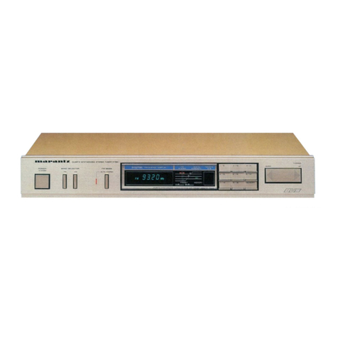
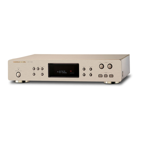
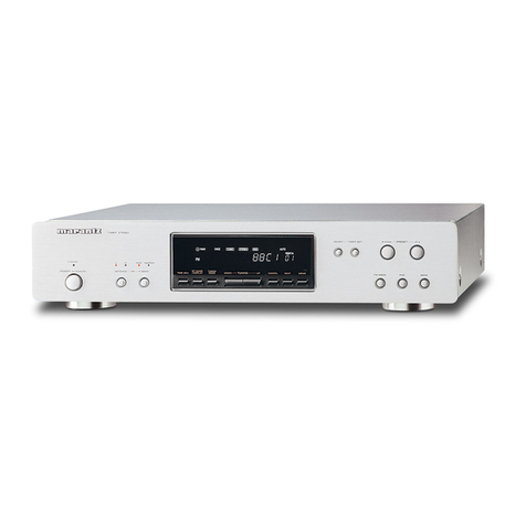
Marantz 74ST48/01B User manual

74S
T48/018/028/05B
Synthesizer
Stereo
Tuner
TABLE
OF
CONTENTS
SECTION
PAGE
q.
TECHNICAL.
SPECIFICATIONS
inccsti
ates
iuc
htc
sarees
dennaedevecchewuclpuatdas
netakeehecsmanranens
1
BS
AAIVERVIN
GS
DIGI
sso
cictcsca
seat
ccenccnccenncnseceedeties
inctace
ess
sh
des
aside
alel
ow
lacs
hese
avagia
Ae
aata
ain
eos
aaa:
2
As
ETC
HCD
iG
aa
ebais
fs
eta
tes
Ses
cos
nent
et
vcncsesinen
secon
soles
hades
Gestiva
nua
dedsteieboosanannaeaamaaiendbes
3
4.
SCHEMATIC
DIAGRAMS
AND
PARTS
LOCATIONS
(COMPONENT
SIDES)
........cssssscseeeseeeeeeeees
5
5,
ADJUSTMENT
.....ccccccccccccoceccescceccesceeeeceaveccnees
eases
apt
e
eeeaeteye
ee
ca
reat
hanes)
15
6.
EXPLODED
VIEW
AND
PARTS
LIST
.o.c.ccccccccccccccscsccececccesesseccscescscecsccacsacseasaressecesevacuenenansnesetsseanaces
18
7-
ELECTRICAL
PARTS
LIST
cui
soreness
titties
eile
eds
e
ert
aoa
19
NOTES
«
PC
boards
shown
are
viewing
from
parts
side.
«
The
parts
with
no
reference
number
or
no
parts
number
in
the
exploded
views
are
not
supplied.
*
As
regards
the
resistors
and
capacitors,
refer
to
the
circuit
diagrams
contained
in
this
manual.
+
Paris
of
[]
mark
can
be
used
only
with
the
version
designated.
[GE}:GENERAL
EXPORT
[EUR]:EUROPE
[UK]:U.K
Piease
use
this
service
manual
with
referring
to
the
user
guide
(
D.F.U.
)
without
fail.
|
4822
725
5117
First
issue
:
1908/0:
PCS
98
441
|
243We855016
3t

MARANTZ
DESIGN
AND
SERVICE
_
Using
superior
design
and
selected
high
grade
components,
MARANTZ
company
has
created
the
ultimate
in
stereo
sound.
Only
original
MARANTZ
parts
can
insure
that
your
MARANTZ
product
will
continue
to
perform
to
the
specifications
for
which
_
itis
famous.
| | |
Parts
for
your
MARANTZ
equipment
are
generally
available
to
our
National
Marantz
Subsidiary
or
Agent.
ORDERING
PARTS
:
|
Parts
can
be
ordered
either
by
mail
or
by
Fax..
In
both
cases,
the
correct
part
number
has
to
be
specified.
The
following
information
must
be
supplied
to
eliminate
delays
in
processing
your
order
:
1.
Complete
address
|
2.
Complete
part
numbers
and
quantities
required
3.
Description
of
parts
4.
Model
number
for
which
part
is
required
5.
Way
of
shipment
6.
Signature
:
any
order
form
or
Fax.
must
be
Signed,
otherwise
such
part
order
will
be
considered
as
null
and
void.
USA
MARANTZ
AMERICA,
INC.
440
MEDINAH
ROAD
ROSELLE,
ILLINOIS
60172
USA
PHONE
:
630
-
307
-
3100
FAX
:
630
-
307
-
2687
CANADA
LENBROOK
INDUSTRIES
LIMITED
633
GRANITE
COURT,
PICKERING,
ONTARIO
L1W
3K1
CANADA
PHONE
:
905
-
831
-
6333
FAX
:
905
-
831
-
6936
EUROPE
/
TRADING
MARANTZ
EUROPE
B.
V.
P.O.BOX
80002
BUILDING
SFF2
5600
JB
EINDHOVEN
THE
NETHERLANDS:
PHONE
:
+31
-
40
-
2732241
FAX
:+31-40-
2735578
KOREA
MK
ENTERPRISES
LTD.
2F
SHINHAN
BLDG.,
247-17
SEQKYO-DONG
MAPO-KU,
SEOUL
KOREA
|
PHONE
:
+82
-
2-323
-
2155
FAX
:+82-2-323-2154
PROFESSIONAL
CANADA
TC
ELECTRONICS
CANADA
LTD.
540
FIRING
AVE.
BAIE
D'URFE,
QUEBEC
H9X
3T2
CANADA
PHONE
:
514
-
457
-
4044
FAX
:
514
-
457
-
5524
PROFESSIONAL
USA
SUPERSCOPE
TECHNOLOGIES,
INC.
MARANTZ
PROFESSIONAL
PRODUCTS
1000
CORPORATE
BLVD.,
SUITE
D
AURORA,
ILLINOIS
60504
USA
PHONE
:
630
-
820
-
4800
FAX
:630-820-8103.
THAILAND
MRZ
STANDARD
CO.,
LTD.
746
-
754
MAHACHAI
RD.,
WANGBURAPAPIROM,
PHRANAKORN,
BANGKOK,
10200
THAILAND
PHONE
:
+66
-
2
-
222
-
9181
FAX
:
+66
-
2
-
224
-
6795
HONG
KONG
FORWARD
INTERNATIONAL
CORP.,
LTD.
3/F.,
BLOCK-B,
WO
KEE
HONG
BLDG.,
585-609
CASTLE
PEAK
RD.,
KWAI
CHUNG,
N.T.
HONG
KONG
PHONE
:
+852
24942033
FAX
=:
+852
24101656
BRAZIL
|
MARANTZ
BRAZIL
CAIXA
POSTAL
21462
CEP
04698-970
SAO
PAULO,
SP,
BRAZIL
PHONE
:
0800
-
123123
(Discagem
Direta
Gratuita
FAX
+55
11
534.
8988
MALAYSIA
WO
KEE
HONG
ELECTRONICS
SDN.
BHD.
NO.
102
JALAN
SS
21/35,
DAMANSARA
UTAMA,
47400
PETALING
JAYA
SELANGOR
DARUL
EHSAN,
MALAYSIA
PHONE
:
+60
3-
7184666
FAX
:
+60
3
-
7173828
SINGAPORE
FORWARD
MARKETING
(S)
PTE.
LTD.
23,
LORONG
8,
TOA
PAYOH,
©
SINGAPORE
319257.
PHONE
:
+65
2583640.
FAX
:
+65
3564047
TAIWAN
PAI
-
YUING
CO.,
LTD.
6
TH
FL
NO,
148
SUNG
KIANG
ROAD,
TAIPEI,
10429,
TAIWAN
R.0.C.
AUSTRALIA
/
NEW
ZEALAND
SCAN
AUDIO
PTY.
LTD.
52
CROWN
STREET,
RICHMOND
3121
VICTORIA
;
:
AUSTRALIA
PHONE
:
+61
-
3
-
9429
-
2199
FAX
:
+61
~
3
-
9429
-
9309
PHONE
:
+886
(2)
5221304
FAX
:
+886
(2)
5630415
JAPAN
Technical
MARANTZ
JAPAN,
INC.
35-
1,
7-
CHOME,
SAGAMIONO
SAGAMIHARA
-
SHI,
KANAGAWA
JAPAN
228-8505
PHONE
:
+81
427
48
9379
FAX
:+81
427
48
0889
AA
VOLVY
®t
=
+
|
A
tt
7228-8505
#8
Fe)!
PRA
EIR
THERA
7
-
35-1
SHAR
TF
150-0022
MRRRS
RRMA
1-11-9
SHOCK,
FIRE
HAZARD
SERVICE
TEST
-
|
CAUTION
:
After
servicing
this
appliance
and
prior
to
returning
to
customer,
measure
the
resistance
between
either
primary
AC
cord
connector
pins
(
with
unit
NOT
connected
to
AC
mains
and
its
Power
switch
ON
),
and
the
face
or
Front
Panel
of
product
and
controls
and
chassis
bottom.
| |
|
Any
resistance
measurement
less
than
1
Megohms
should
cause
unit
to
be
repaired
or
corrected
before
AC
power
is
applied,
and
verified
before
it
is
return
to
the
user/customer.
:
|
Ref.
UL
Standard
NO.
1492.
In
case
of
difficulties,
do
not
hesitate
to
contact
the
Technical
Department
at
above
mentioned
address.
PCS
98
442
a
|
|
:
:
|
9802
183K

1.
TECHNICAL
SPECIFICATIONS
FM
SECTION:
7
|
Tuning
Range
....essesessseseereeseeees
sb
aletdte
dee
h
ci
acaslanede
coaten
tan
ease
aera:
87.50
MHz
-
108.00
MHz
(50
kHz
steps)
Usable
Sensitivity
(JHE)
..csssscccssescccesesesesssessesseesssesesnesenseesnsmeeeconsnsannaveccnanesssgsrarsaastsaensnenannecnegnersesessy
iets
Mono
10
dBf
50
dB
Quieting
Sensitivity
..............
Bede
tin
tesniciuess
Sha
iulaeandhectss
esaesdinama
oneness
Sone
Aas
attests
Mono
10
dBf
Stereo
33
dBf
Alternate
Channel
Selectivity
(400
KHZ)
......ccescesceseseressssessessneneensanensorsesnenessnannnaenanensneeeeneeneegeegseg
ee
eet
eT
65
dB
Image
Response
Rattio
.......eseceeees
_cccoscssaueusnaeusauasarsssuaectucersesvrsssernecsneccusssorsevensnosnreceacsacsusesssaneoosoconsaenenagananansrt
60
dB
Frequency
RESPONSE
.......--scscesrseeressetsecrerestenseeees
aaeiuaess
cdlecsideneatea
cess
(idsseaste
amasuetens
cluded
Sore
deastevaeielay
tance
60
dB
Capture
Ratio
.........
eee
E
aaah
tus
camps
alo
dahl
cba
kulicsee
ib
ada
e
es
woe
ener
cans
SR
(aie
esa
pons
avec
ene
ase
eeR
Ia
Eze
Ree
2
dB
Distortion
(at
65
ABE,
1
KHZ)
.....ccsscscsscecseesesstestesessesenseneenseneennscssnssssssecnnnennnsnsanyensseeeeeesne
et
eeete
ttt
te
EI
Mono
0.2%
Stereo
0.3%
Signal-to-Noise
Ratio
(at
65
ABE,
1
KHZ)
........eeersessesssessssseeenententesnennsnenecaeecentees
bch
sctak
Deis
Guludeuntunneees
same
seen
Mono
70
dB
Stereo
65
dB
AM
Suppression
Ratio
.........cscsesssssscesreesserenssvesssessnsessnenensensensenserssscsnsenacnacasanensrenseeseenseesneeses
seen
g
ee
eee
nidateaiecutateneets
80
dB
Stereo
Separation
(1
KHZ)
......sccccesereestseesssereneneneseseessersernscnserenscnconentanninsserestes
<cassegebesasmavaselanwesee
Liou
tducaeaceaeaa
eetoa
eke
40
dB
OQUtPUt
0.0...
ccssereenecerens
oe
iu.
assist
ak
ia
SatnceReat
Hideous
page
ve
wasnanaueaavabaiiventOa
cnbane¥i
sna
ceabaermsancaateiansnsbnbewnetatacentnedaexvensiteyeTnsy’
600
mV
"M
SECTION:
|
Tuning
RANge
.sscsscsssssessecsseneccssssonsessessssessnsescsnesssssnsessessascnsocannavsouscocsaensesarannasszanecensnenssstt
522
kHz
-
1622
kHz
(9
kHz
step)
Usable
Sensitivity
..........:ceseeeereeeees
Ue
ated
oudsbe
satsdg
beset
eeatataeitacaanae
se
sesnveasacecsesavesesssanensacsssesansssunnornqasususnenssenseanensesesnese
55
dBm
RTE
eect
1
5
PTET
OCT
eae
ace
55
dB
(9
KHz)
Image
Response
Ratio
.......cssssccsssessnsssseeesssssssssessnscensstnssenseenconssersessenssesees
eee
sitnee
tee
e
tee
ete
eT
A
35
dB
ESTE
ITAL
COT
scxcassiis
cached
nec
ta,
ghee
emia
vote
ines
Stace
pga
ana
Sennen
nas
eee
ae
men
arr
1%
Signal-to-Noise
Ratio
.......ssccsseccsssserssesssnsessssecssessenessssennsernensvanescecernnnanancansconenaaseneesseeesenteas
aes eee
etter
eee
40
dB
(at
85
dB/m)
Output
tect
eect
le
cada
cee
nea
a
Sead
ede
ee
ana
ARS
2a
ceecadeanyeameaneean
aren
170
mV
GENERAL:
|
Power
Requirements
..........
sessanenensssneeecoanasnecersesceutaseuenenseconennossrocecensanensenege
i
ciechanehinseaienessnceemianen
een
230V
AC,
50
Hz
Power’
Come
upton:
siseviscsccucsodssessdunicivssvcassodssancustacandsyesnntestivnttatinssisapsiibexesesrtpesci
tap
sins
ensieaaetsertrarrentann
tints
ese
ST
6W
DIMENSIONS
(WX
HX
D)
.rissssccsisrsscscosssresssneeceonnensensnssarenenennsnuseneranecbsenaraengersnnansussesraesoncerneasnecsonarererenseseeneets
435
x
87
x
294
mm
AVIA
UV)
cass
cans
pcetirecans
thas
enasanenes
graves
tavos
ence
ents
es
cytes
tenet
steverenesn
ene
errr
eee
2.9
kg
Design
and
specifications
are
subject
to
change
without
notice.
RODUCT
SAFETY
NOTICE
Many
electrical
and
mechanical
parts
in
this
chassis
h
These
characteristics
are
often
passed
unnoticed
by
a
The
use
of
substitute
replacement
parts
which
do
not
have
the
same-safety
characteristics
as
§
cause
shock,
fire
or
other
hazards.
|
ave
special
safety-related
characteristics.
visual
inspection
and
the
protection
afforded
by
them
cannot
necessarily
be
obtained
by
using
replacement
components
rated
for
higher
voltage,
wattage,
efc.
Replacement
parts
which
have
these
special
safety
characteristics
are
identified
in
this
manual,
electrical
components
having
such
features
are
identified
by
the
schematic
diagrams
and
the
parts
list.
| |
Before
replacing
any
of
these
components,
read
the
parts
list
in
this
manual
carefully.
pecified
in
the
parts
list
may
ee
naemaanmie
inte
an
mumerntmerem
anit
ge
ys
anes
te
reyes
Ss
ies
ie
ee
ore
re
eet
cae
ne
oy
me
rere
woe
wnat
nemitee
pee
mite
em
ll
-
-
:
each
Tat
ce
tenance
ee
erin
2.
WIRING
DIAGRAM
C-LELLdNY
Ls]
Libby
¢NO
SOND
I-Z2bHd
Ay
biND
;
~
y-LEuL
dy
———
awn
See
me
yee
qe
_|
ZH
OS/AGEZ
‘ASL
OW
407
XINO
10/
ZH
OS/AQEZ
OV
GO/
‘Z0/

3.
BLOCK
DIAGRAM
Fi
FRONT-END
oF
101,102
CF2
+B
LL
T102
CT]
48
9-0
REG
LOOP
ANT
¥R3
SEPERATION
ADv.
POST
gang
ae
one
(2)
FILTER
4
CECODER
|
FF
FF
|
[STEREO
38KHz
F1iSKkHe
Fy
Sw:TCH
H
14
"
MC4558S
Paoveediiey
S
eis
FM
GF
&
i
Laizes
|
AM
RF,
OSC,
MIX
=
|
|
|
=>—©
~
||
:
/\
SYMMETRICAL
MUTING
REACTANCE
am
TRIGGE
|
LED
CIRCUIT
lo
i
DRIVER
t
ee
|
*
Osc
i
PHASE
oe
LED
a
u
ees
|
COMPARATOR
DET
DRIVER
)
oe
i
eu
i
1
YS
tm
|
(=z
——_
|
a
|
=o,
|
2g
=>
—3-
7 :
2
DRIVE
—+
+5V
r
{
>
ij
(ee
|
__)
7]
ORIVE
|
i
ae
=
“sie
¢
J
—
lye
|
4
|
<
:
As
'
[<6
:
)
H"3
|
4
hi
‘
a
eH
4
=
$
}
Fa
road
—_}——
as
i
22
‘
i
|
a5
=
<4
ax
ie
|
Bei
aks
[Sz
|
a
te
psi)
>—erh
|
AR!-DKDET'_!
aaa
es
|
|
gs
|
a
<
j
Wuleue
OET
:
Neied
\
a.
i
$
4
+
2
=
—
|
co
ae
=
—)
in
[t
or
i
psi)
Pe
Oe
ofr
H+
EVELOET
+H
j
|
:
FM/AM
nan
Fu
ae
SWiTCH
(7)
Ll
+B
AW
t
‘
‘
:QNO~113
Co
C7218
RA
PLL
CONTROL
a
Ly
ee
ee
ee
ee
ee
bHe
;
POWER
STIN
YQ
SIN
SIGNAL
oe
@)
CLOCK
(19
;
7
G8)
aos
|
vata
(1)
’
|
+8
49
START
é
|
eee
MICRO-CON.
POWER
5
t
+12¥
SWITCH
.
ad
Zz
RNC
IN
IN
Q703,704
a7)
DRIVE
{only
EUR
&
U.K}
Sag
RUC
OUT
Rewete
{_>
REMOCON
AC
115,230¥/S0H2
F791
T
200mA
4
4
3
4
'
|
t
§
AC
239V/50nz
|
;
5
AM
IF
SIGNAL
FM
OF
SIGrAL
|
AP
SIGNAL
FM
OSC
SIGMAL
oor
Bs
Se
ERPS
a
AM
DEL
SOWAL

.
SCHEMATIC
DIAGRAMS
AND
PARTS
LOCATIONS
(COMPONENT
SIDES)
ERSION
/
01
a
|
=>
|
|
|
.
LBK
o
1.8K
FEI
|
CFY
|
Ss3°TS
=—ss
x
Se
cr2
|}
BPFI
? |
Ben
25
oN
=
>
ra
3
oO
Fo)
ey
w
NS
a
css
Rize
SERVICE
INFORMATION
8158
0,047
~*
Gn
x
ry
.
Resistonce
vclues
ore
indiccted
in
ohms
unless
.
w
.
;
z
ys
C187
|
2.
Copacitence
values
ore
indicoted
in
microforods
unless
SP
otherwise
specified.
(
P=micro—microferad
}
3.
All
voltege
ove
measured
with
ground.
L105
C186
DC
:
volue
with
no
signe!
BiG?
K¥12362
;
47P
AC
:
RMS
(
ot
1KHz
Bohm
toed
full
signal
)
|
.
Y
en's
4.
PRECAUTION
ele
A)
Ali
covers
shields
ond
insulotig
spocers
must
be
&
&
€
o
S
s
reploced
before
returning
oprliance
te
customer.
on
ie
s
l—
Ci70
dak
ene
B)
A
damaged
powse
supply
cord
must
be
repioced
470P{S)
:
@
before
returning
appiience
to
customer.
get
x
C)
Dielectric
test
should
be
done
before
returning
;
2SS~=
A
ees
O O
asplicnce
to
customer.
mEem
ToS
D)
Since
those
ports
marked
with
beer
critical
&
ek
ports
for
sofety.
Use
the
one
described
in
parts
list.
@&
|
R126
TPO2
|
OK
C149
|
|
|
mizz
49/90
|
360
CNB
Rtas
|
Q107
x
CI7405R
AL
ab
xk
5
|
|
cng
=
R147
|
+
a
——fy---
Sse
eas
C163
10/16
rP0
es
SS
al
arta
5.6K
R145
mi
ow
~~
ans
s
=
DS
|
=
3
wa
xfs
Cats
|
C106
ores
*
nl
a4
H
i
ci740SR
|
Pe
VR3
|
.
3/50
200KB
«C161
|
|
rises
om
|
'
wt
3
Ral
C126
N
~
e
|
;
wox
2162
+
|
4
to
a
-~
=
ome
1.
i
is
5
5
o
CiuatTs
Lg
/
~
-
4
ry
I
XOUT
YSS
PD2
PD!
VDD
FMIN
4MN
SOTE
LCTR
CUTE
(13
-—(i2
{1
($)
7
$
tt
tal
}
ee
pon
BUTS
SEP
MO/ST
STN
2
.
Ic3
P
A341
S
2
Ni
1N4146
LAS410
as
a4
ey
DIO7
Chars
IN41ZE
R184
A
5
a
i
A
Y
X6
Jo
)
a
ea
Ci4t
C142
Bs
0.047(M)
560P
560P
RIT]
RIGS
R157
ot
RI72
C185
|
x
saps
MAY
nD
Wi
4.7450
Wo
Stu
nZQi,
WK
JKOS
she
2.7K
91K
3.3K
OS
a
C18O
aN
2
Ss
R724
ica
ee
Bi
mapa
:
%
<
=
100
Sy
+
C165
RI6B
a)
(3)
10/16
150K
150K
{
wen
|
&
Sr’
|
w
Sx
mek
|
ge
re
2-8
3
&
eexBse
|
Sey
EeEoT
Ss
<<
xe¢n
|
|
O12
D1De
RV77
10K
C178
Ay
3.3/50
Qs
18
100K
cial
0.0012
FS
oa
Se
—
CI740SR
7
0701
IN414B
INA
148
2
2
a
i)
yh
1N4003
S;
Se
g
I>)
©
tSxrs™
(~~
2
=
2
Sr
sees
iC
4
(
Be
,
a
wh
x
:
Qs
i
Q117
“es
0120
ES=
ants
¢
v9)
oe
CI740SR
f
Z
><)
-
+
6
ES
|
:
JKOE
ac
230/N5V
,
S0/s0H2
|
O12
AL
|
Ci740SR
~
6
ve
numemnnitnstrat
tte
nite
miei
erie
ere
a
eetsnteneth
Nr
tteer-natted
ete
Date
o
Seo
|
nS
Pe
a's
|
et
a
EE
Be
le
LTS
6
5
4
ne
|
CNg5
»-
{

VERSION
/02
/
05
‘
0S/L'¥
MEE
4
802¥
£429
JKQ6-
S
|
é
Sere
499
NS
:
a
a
©
O)
cozy)
,
4)
C)
i
apeticant
moe
MMAR
pg/L
Kh)
61Zz9
Aviva
Qe
.
ai
f<
)
9
es
459-9
ip'0
t—#)
OC:
mi
S93
19'0
caaemaememaaam
|
}+—
ne
a
or
of
O)
Balls
=
Oe
(¥)a900°0
a
AMT
=
gozy
a
Q
we
.)
~
@
LO2N
D
gy
$955
ew
nds
tis
sothnaecidlips
estan
“yace
,
a
ot
‘ares
Saeed
ain
102X
*
[hoe
Oy
—}
8
io
91/01
ae
OL
3S
|
|
Cay
BrLeNt
vi
&
-~
O
rs)
5)
asa
—
é
SS
Dod
DR:
-
sz
o
ey
a
.
+
oz
d06E
|
HAY
9¢ld
pamicneaee
=
.
2
YO
+
ws
=
we
=
;
=
‘
:
ba
q
.
oO
~~)
;
a
TN
:
“7
ee
Gy
>
4
mt
=>
ses
intl
ie
Ln
al
Cy
xf
A
sea
sa
scaaseSernsanontalacie-aine'Dy
“sone
sd
-
“ay
iw
*
4LP
Xi
NSS
C1740SR:
Y
c
ann
10/16
eS
Cen
+
nae
ete
een
teen
ete
a
etre
amar
i
eo
et
tiene
+
few
tenn
Reet
sen
natetnae
pee
ant
teen
ie
hem
Sere
rhe
oe
5
‘wel
ole
5
x
o>!
Z\
if
y
.
OCf/1¥O
+
£G19
tox
a,
Senenicesiaaie
6
|
j
tor
|
ariz
All4Y¥S
R152
_}i
als
22K
ei
eee
ee
<3
{
if
2°
Qit4
CusrTs
Qi
Alis7¥S
O10
IN414§
ML
Aree)
oar
aeaarnenmnnaire
geese
wal
Srieriad
eastern
Sanne
i
ok
<7
<9
<
vara]
@
e
6
z.
cane
:
_4
|
LX
9XSX*XEX
XY
|
a>
es
:
LZNO
ike
azine
‘
$oOx3O¥
4
=
=
tae
=
Lina
wv
/WJ
yo1
GCN
R15
39K
R154
10
18
R14
pm
AA
0.01
4
CugS
R147
VV
0.01
4.7K
|
R145
A
10K
O13
CUaTS
0107
RiB4
IN4148
MV
at
2
100%
,,
+o
na
2
ia}
mw
~~
o
Q116
SEE
BEERS
7
SEE
Ee
ee
ee
;
ie
te
r
+
ha
”
MINAL
4
,
i
iB
“sz
|
33x
<J
™
on
oy
1+
evaiiaael
i
1
C4
=
Bt
1
os
Ry
)
;
Opn-ponndef
!
!
2
3
Md
i
’
Oy
:
,
se
‘G
atin
eee
ar
callg
ad
Ca
.
<J
4
ro
‘
da.
ro
OI
a)
Paty
AO
AOL
ALE
:
a
ae
‘
Stty
ne
ae
:
‘
$
Or
[
;
)
IG
/E'E
a
:
7
*
©
gu
°
peers
WES
“e)
¢
s
oF
oS
8
os
;
3et3
.
es
joss
Sas
on
7
ee
ts
oe
a
be
>
4
re
‘A
5
Vv
:
8
£0
oasel
{tl
eage
.
ESP
¢
¢
e
~
kd
re
:
:
*
-
fF
001
wate?
;
é;
<P
S858
B
soaea
<
Cpanel
pipe
he
4
{
sa
ee
{
895
5
&
Bae
S
§
&
aye
ag
2019
e
Re
i
74
on
8
¢
+.
Sie
.
ee
ae
:
=
v2)
z
fos
"
§
3
a
20"
|
Si
a6
Go
EP
EBs
ag
wSEPF
,
ode
fe,
rene
:
»
2
oly
Streets
2
Saeee
4
€:
Or
Tee
gere
ies
a
a
Bites
enn
onde
Cae
:
=
aS
2
b-
.
Ae
13
9
i)
$F
s
5
4
py
.
uy
eet
OTs
ae
fl
=
sg
0
fs
9
3
a
o
eo
Bis
erabeaatecliedteg
nnn
see
|
S
eP
Fe,
*
ECE
®
%
7
e
S8stsce
Tesitce
te
Lal
:
‘
seme
om)
ox
Da
*
FS
ES8au
8
+l
PN
ta.
SLEL
yp
se
o
7
838
|
z
=
ae
ee
ee
ee
ee
a
ee
52°28
°**
Zesoexy
%
B
E
ul
Fe
y=
os
Se
*
5
8
oe
e
re
oe
UES
«ws
rs
2
e
Fs
.
=
SR2R
LF
SLRS
ves
\
oe
re
er
a
re
sere
gb
y
»
©
Wi»
o
se
©,
CX
HX
SX
9K
ZX
BX
6XOL
i
SES,
sxRS
tes
qas
=
riX
&
é\.
peel
fo
Nw
“”
gree
eSeorse
sss
e
4
ind
ee
ee
i
£6
£
8a;
Beet
>B8ler
8
GB
of
o
=
oc
aw
<
a
=
i]
Oe)
~
ues.
Yge
the
one
descr-nee
in
parts
‘or
safety.
ports
DMSO
OC
AAR

UP11117
YANN
pep
San
PARR
ARE
TREN
Re
RIE
2A
ARTE
aera
At
Q120
Q121
Q701
IC22
Q702~Q704
RDS
SECTION
CED
120
0704
Magee
ats
:
gee
Qe
CBT
EL,
Npoe
3425(x
425
at
i
ae
Terai
i
Q118.Q119
ICO1
_
Q1d1
Q114
-
Q106.Q107
ICO2
IC03
Q115~117
Q111-Q113
Q109
at.
:
Cae
©
crsi
“Se
ge
nag
+
A
-
t
4
ae
|
A
a
ORIN
t.
)
etait
|
RIGS"
R726
T450(0)
P
aR
seems,
WS
10132:
focal
pock—j125
insert
.
export
pack—ci25
insert:
£.
ae
ee
~
&®&
:
kM
}
eg
nes
¥
i
e
aah
“He
ie
ot
fy
y
% &
etre
4
A
.
"4
SEPERATIOX
ADs
16!
ae
ic
weet
Function
of
Terminal
(IC2)
BVILC7218
(LC7218)
oe
|
DO
Data
output
terminal
for
control
v5
[7
|
NPUT
|
_INO___|
Control
input
for
dataformat
[Te
fp
eur
|
C—“‘“S*S*S*S*S*™S™CC~*
MUTE
ON:
*H"
,
MUTE
OFF:
"L"
FM“
AML"
[2]
_oureut
|
__0uTs__|
Not
used
inthis
unit
|
3
T
oureut_
[|
outa
__|
STEREO
:
"L"
,
MONO:
"H
[ie
|
wer.
s|
RSs
SCSC~CSSC~‘dz
[—a7__|_ourput_|
outs
|
OuiputierminalforiF
detector
[78
|
INPUT
|
__
AMIN
|
Input
for
AM
OSC
output
input
for
FM
OSC
output
[20
|
_NpuT__|
VoD
___|
Power
supply
terminal
Not
used
in
this
unt
p23
f=
|
VSS_|
Ground
terminal
Function
of
Terminal
(1C91)
BVIANAM1239T
(TMP87CK78F-xxxx)
PIN
NO.
|
IN/OUT
MARK
i
DESCRIPTION
OF
TERMINAL
1
i
INPUT
VOD
Power
supply
terminal
—
2~5
|
INPUT
KEYO~-KEY3
=
jinput
terminal
for
key
6~10
:
|Not
used
in
this
unit.
14
'
INPUT
|
RDSDATA
Data
input
terminal
for
RDS
13.
|
INPUT
|
RDSSRART
iCiock
input
terminal
for
RDS
14~16
+
GND
{Ground
terminal
Option
terminal
for
area
/01B
/02B./05B
DESCRIPTION
OF
TERMINAL
'Signal
level
indicator
drive
Not
used
in
this
unit.
feta
nase
alll
Ground
terminal
24
INPUT
|
VREF
i\Referance
power
input
terminal
INPUT
voD
|Power
supply
terminal
26
|
INPUT
|
CE
Power
supply
detection
27
|
-
|
Ground
terminal
28
|
INPUT
|
IN
{Connecting
terminal
for
crystal
osciliator.
29
|
OUTPUT
|
OUT
‘The
crystal
connected
is
32.768KHz.
XIN
Connecting
terminal
for
crystal
oscillator.
XOUT
_[The
crystal
connected
is
8.00MHz.
RESET
{System
reset
termina!
34
|
OUTPUT
RMC
OUT
{Remote
control
output
termina!
35
|
INPUT
=|
RMC
IN
iRemote
control
input
terminal
36~42
|
-
[Not
used
in
this
unit.
43
|
=
OUTPUT
POWER
‘Power
on/off
signal
44
|
INPUT
SO
IN
‘Station
detection
45
INPUT
ST
IN
Stereo
indicator
drive
46
|
OUTPUT
|
BO
,Data
output
terminal
for
1C2(LC7218)
47
|
INPUT
CLOCK
{Data
input
terminal
for
1C2(LC7218)}
48
INPUT
Di
|Data
input
terminal
for
1C2(LC7218)
49
=|
OUTPUT
[Chip
enable
termina!
for
1C2(LC7218)
50
INPUT
|
51~64
Véip
IFIP
drive
voltage
input
OUTPUT
G0i~G14_
—s
[FIP
digit
driver
outputs.
iNot
used
in
this
unit.
|FIP
segment
driver
outputs.
iNot
used
in
this
unit.
Output
terminal
for
key
OUTPUT
|
97~100
OUTPUT
S01~S20

PCS
98
448
>}
7
oF
™
2
CE
wT
Hae
|
{
|
|
|
=
dr
meets
mene
ae
cent
Lee
ene
Re
m
D902
a
41+
47K
ie
ne
cag
meng
maces
ead
aie
=
ee
mene
SAD
a
NO
ERTS
EROS
SO
MR
me
MLN
Se
Se
:
D903
a
it
ome
Piped
in
=o
Crs
“Ze
N
i
C965
RII1B
47K
DS
CLOCK
4p
{RDS
DATA
2
ROS
STARTS
D901
moe
|,
cols
Ls
4
Se
|
oe
~s
box
|
gis
agi
ee*
OPTION
ase
woe
at
soo
=~
N
3
|
OFF
e
+
100k
1AM
10k
Torte
tien
fa
eae
anette
{
{
i
1
D'UMER
ob
SLEEP
;
y
aff
Jd
a
TIMEAQY
TIMERADU
FILE
yd
a
NEXT
i:
s5
cil
s6
$7
Ass
ya
CH
DOAN
|
WEMORY
yl
20S
$12
Dae
ROS
START
ROS
DATA
ROS
CLOCK
WL
|
cH
UP
|
I
$9
Yo
eS:
Hy,
D
q
i
|
C)
ST/MONO
heme
.
ROI
“OOK
NV
R902
d
100K
R903
AN
00K
R904
‘
LOOK
FIPY
CM1409C
1
FL
EN95
™
ut
me
OS
KUS
Gamay
SERVICE
INFORMATION
N
)
~~
el
|
2}
3
s
1,
Resistonce
yolues
ore
indicated
in
ohms
unless
A
eat
es
o
otherwise
specified.
{
K=1006,
M=1000000
)
e
2.
Copacitence
values
are
indicated
in
microfarads
urlees
;
atherwise
specified.
{(
P=amicro—microforad
}
j
3.
All
voltage
ore
~easured
with
ground.
|
3C
:
volue
with
no
signe!
:
i
AC
.
RMS
{
et
!KHz
Bohm
ioad
full
signal
)
4.
PRECAUTION
i
|
4)
Ali
covers
shields
ang
insulotig
specers
must
de
|
replaced
Sefore
returning
app:ionce
{o
customer.
|
B)
A
doemoged
power
supply
cord
must
be
replaced
before
returning
appiance
to
custemer.
|
C)
Diewectric
test
should
be
done
before
returning
f
appliance
to
customer,
eceeererrnneene
name
annette:
wee
0)
Since
those
parts
marked
with
LXer
critical
ports
for
sefety,
Use
the
one
described
in
ports
list,
$16
ys
|
TUN
U®
TUN
DOWN BAND
ere

A
sepa
ue
11127
a
|
:
:
Cot
a
Q907
ke
wey.
Hiatt
Dir
nineihas
bs
KUP
1112
7-2
TUNING
DOWN
Al
2
hh
TUNING
UP
cM
UR
SNR
RAK
Nd
LORETO
TROD
F701
-
2200mA
L
250V
F702
T200mA
L
250V
BESS
Seah
SU
oR
NCEE
CTEM
(L)
(BROWN)
KUP11127-4
F703
ASD
2A
0
T200mA
L
250V
Pye
mae
ae
ERR
Cont
NS.
ae
ae
eat
ae
TRIN
second
5
nena
rere
panama
ag
PRL
UR
POL
Aon
DEPRES
A
4
RIES
_
ai
rs
eo
Na
CRANE
$..
¥
pate
ate
BIN,
RRR,
IRONY
MHA,
ENN
an
*
b
ene
a
RLA
REE
RNIN
TOON
AAR.
a
9
RLY
A
ID
RLF
Haha
seni
3
%
ee
asa
anet
SARNIA
a
YEAR
OA
RE
ROO
A
ius
con
nf
Cf
re
Teg
a
Ne
SE.
a
re
a
fis
Neeenener
hy:
niente
sat
arenes
Neh
erent
We
Neale
net
ts
same
ns
Meee
ET
Aten
ee
q
white
ee
7
%,
%
"
*
Nea:
eck
a:
A
EP
renncssin
=
FAMER-ON
/
“oe
4761
—=£
Rg
t
‘i
:
mts
a
a
#
&:
z
”
MNS
.-
yy
(IC
TCT
IAD
IIAD
2
3
PN.
2
arias
a
ee
:
Fe!
J
Wale
wee
gg
|
oes
utneania
eran
natn!
6"
eee
500s
Styrene
etka
Ree
ae,
Ps
See
ee
ee
Sao
‘HNO
me
C90}
a
Lh
ee
.
te
RONG
aa
te
emromearcmnneeeenee/
orien
mani:
‘east
a)
see
nee
gs
Xe
oe
sme
nN
rats
MOTE
pe
wainipereee-
SRE
ME
NS
BORING
EE
ESOS
AT
OL
LEW
AS
ERIN
a
OOD!
HORS
ALT
‘.
“FIRE.
s
Ren
Pe
ett
eee
ae
‘
“FIRES
EXF
FAM
Sephora
ht
RB
i
aa
eR
SY
Bailie
RE
ceapeeee
POWER.
a
Big
Ss
GE,
atts
srenaciacs
cunice
amen
aneie|
z
sis
Sey
actA
APS
ONE
SM
Finer
‘
KES
may
%
a
Mie
LI
i
ge
ts
ae
oA
ET
EP
ME
Romer
ecrernana
nt
-
=
SREP
RAT
x.
&
tr
z
SERA
ee
Ienbeonenerrantamre
rity
—
pos”
ve
“(osprey
Pe
ee
NCATE
THANRN
BE
FONENING
NS
MERON
bee
Su
bccn
aon!
eeenore
mak
x
ihe
arden
ated
asandeih
eae
oo
pte
maz
EO
A
*
Pee
*
e
%
‘i
ve
£
es
4
ies
:
2
Re
RE,
OER
ghee
sane
sacraasapigiindinta
cae
vv
+
PARE
NEE
MRL
mney
ce
ernie
ite
fie
oa
rawacnrese
7
Dh
SC
Sah
eh
LMI
OH
a
ee
ar
Ce
oa
¥
.
gore
:
Bidar
wo
oe
i
i
i
nner:
cag
ee
Sig
be
peek
©
9
remind
weiatowtreh
ieapptol
snes
Shee
nae
aaah
rte
atiattete
na
+
neem
AES
res
me
ema
Am
castes
Em
he
ee
|
~14-

5.
ADJUSTMENT
(1)
ALIGNMENT
INSTRUCTIONS
Equipment
needed:
¢
AM
Signal
Generator
FM
Signal
Generator
Oscilloscope
*
VTVM
(AC,DC)
¢
Test
loop
antenna
(MW
Adijustnent)
Dummy
antenna
(FM
Adjustment)
Stereo
signal
modulator
¢
Distortion
analyzer
IMPORTANT:
|
1.
Check
power-source
voltage.
2.
Set
the
function
switch
to
band
aligned.
3.
Keep
the
function
input
as
low
as
possible
to
adjust
accurately.
“=
fodulation
and
modulation
frequency
is
shown
below.
—_—
Modulation
Modulation
frequency
400
Hz
53.3%
(40
kHz)
(2)
TUNING
FREQUENCY
RANGE
ADJUSTMENT
(FM)
DC
voltmeter:
Connect
to
test
point,
TPO1
and
GND
(MW)
DC
voltmeter:Connect
to
test
point,
TPO01
and
GND
|No.
|
Band
|
Frequency
|
Adjust
for:
|
Adjustment
p2
|
mw
|
sezkkz
|
iv
|
103
(3)
MW
TRACKING
ADJUSTMENT
Signal
generator:
Connect
to
the
MW
Ant.
Coil
through
the
loop
antenna.
1.
Adjust
the
scope
to
obtain
the
maximum
amplitude
of
VTVM
waveform.
No.
|
Step_|
Frequency
|
Adjust
for
612
kHz
1
Max.
L102
sensitivity
MW;
2
1503
kHz
Max.
C701
|
sensitivity
a
Repeat
steps
1
and
2
several
times.
AC
EVM
OSCILLOSCOPE
MW-SG
_
ooo
Een
eee:
=
|
MW
Loop
Antenna
(pa
(4)
FM-RF
ADJUSTMENT
Signal
generator:
Connect
to
FM
ANT.
JACK
(FM
IN)
through
the
dummy.
|
Adjust
for:
|
Adjustment
_|
90.10
MHz
Max
L1,
L2,
L3
sensitivity
Repeat
step
1
several
times.
AC
EVM
OSCILLOSCOPE
-15-
PCS
98
450
(5)
FM
MONO
DISTORTION
ADJUSTMENT
DC
voltmeter:
Connect
to
TPO2
(—),
TP03
(+)
through
the
choke
coil
(100
pH)
Connect
to
FM
ANT
Jack
(FM
IN)
through
the
dummy.
Connect
to
the
output.
|
No.
|
Frequency
|
Adjust
for:
Adjustment
{
100.10
MHz
T101
OV
2
100.10
MHz
Min.
T.H.D.
T102
3
Repeat
steps
1
and
2
several
times.
Signal
Generator:
Distortion
Meter:
FM-SG
Ea
(000000
~
a
O00
(6)
9
10ND
——
|
L
—
—'
DISTORTION
|
ANALYZER
Difference
of
R
and
L
must
be
maximum.
MODULATO
(7)
FM/MW
TUNED
LEVEL
ADJUSTMENT
FM
signal
generator:
Connect
to
FM
ANT
Jack
(FM
IN)
through
the
dummy.
MW
signal
generator:
Connect
to
MW
ANT.
Coil
through
Loop
antenna.
Band
Signal
genrator
|
Adjust
for:
|
Adjust-
ment
FM
MW
~16—-

Se
ee
ental
ee
ee
ee
a
ee
owen:
(8)
ADJUSTMENT
POINT
VR22
YRO2
KUP
TT
547
x
3
Li@2
I~
ima)
n
VROS
PCS
98
451
eee
:
it
'
|
3
ii
ae
we

ee
2
.
su
syses:
ve,
ae
ee
ae
2s
Peds
ber
gn
Sealer?
ee
asp
ey
pte
he
cet
ee
ee
ee
ee
Mechanical
Parts
List
4822
450
10437
An
RARER
hg
tte
ee
Pent
—
M
tem
ee
ee
-
hose
ee
ae
ah
eee
eral
hs
ee
_—"
~
5
ve
° 7
a
‘
.
.
See
t
1
ft
ey
a
aac
yma
eb
et
LF
ASR
th
ey
SP
ET
NAR
mine
mite
msensmme
Nar
y
mn
°F
Mota
Peet
ees
4822
459
04883
4822
459
04882
|
422
410
11628
|
|
4822
410
11626
|
|
4822
410
11627
|
4922
410
11632
4822
410
11793
4822
410
11631
4822
410
11629
4822
462
11013.
i
i
i
|
:
|
4822
736
15918
(VERS.
:VERSION,
U:U.S.A.,
F:JAPAN,
K:FAR
EAST,
«EUROPE)
WINDOW
BADGE
FRONT
PANEL
(018)
FRONT
PANEL
(028
/05B)
KNOB
DISPLAY/DAILY
TIME
ADJUST/MEMO
KNOB
POWER
KNOB
SLEEP/TIMER
KNOB
MODE/NEXT
KNOB
PRESET
UP/DOWN
KNOB
BAND
KNOB
TUNING
-
FOOT
FRONT
FOOT
CUSHION
USER
GUIDE
(O.F-U)}
Poo
~18—
243W
158010
243W251010
243W248020
§
243W248010
T.
243W270030
243W270010
243W270020
243W270060
243W270070
243W270050
243W270040
243W057010
243W056020
243W85
1310

7.
ELECTRICAL
PARTS
LIST
ASSIGNMENT
OF
COMMON
PARTS
CODES.
3
NOTE
ON
SAFETY
FOR
FUSIBLE
RESISTOR
:
RESISTORS
note
—_
The
suppliers
and
their
type
numbers
of
fusible
resistors
are
as
xx:
1)
GDOS
x
x
x
140,
Carbon
film
fixed
resistor,
+5%
1/4W
follows
;
-
| |
|
Rx**:
2)
GDOS
xxx
160,
Carbon
film
fixed
resistor,
5%
1/6W
e
batt
aa
Benois
KOA)
PY
eee
ow
wee
=
art
No.
ype
No.
escription
Examples
;
ree
Meeance
vaue
—
NHOS
xxx
140
———e
RF25SxxxxQJ
=
(45%
1/4W)
@
Resistance
value
%
NHO5
x
xx
120
———
RF50SxxxxQJ
=
(45%
1/2W)
0.19....
001
10Q
....
100
1kQ
....102
100kQ....
104
NH85
x
x x
110
———
RF73B2A
x
x
X
X
OJ
(+5%
1/10W)
0.5Q....
005
18Q
....180
2.7kQ....272
680k2Q....
684
NH&S5
XXX
140
———
RF73B2E
XX
X
x
OJ
(45%
1/4W)
19...010
1002....101
10k...
103
iMQ....
105
‘
:
|
6.80..068
3902...391
22kQ...223
4,7MQ....
475
ae
eames
fede
a
#5
Note:
Please
distinguish
1/4W
from
1/6W
by
the
shape
ofparts
2.
Matsushita
Electronic
Components
Co.,
Ltd
|
used
actually.
|
Part
No.(MJl)
|
Type
No.(MEC)
Description
NFOS5
x
x
x
140
ee
aia
ERD-2FCJ
x
x
x
(+5%
1/4W)
CAPACITORS
RFOS
x
x
x
140
|
1
C#*X:
CERAMIC
CAR
>
NFO2
x
x
x
140
—
ERD-2FCG
x x x
(+2%
1/4W)
3)
DD1
x
xxx
370,
Ceramic
capacitor
RFO2
x
x
x
140
ae
al
ne
Disc
type
oe
ee
Resistance
*
Resistance
value
t
Temp.coeff.
P350~N1000,
50V
value
.
Capacity
value
|
Tolerance
Examples
;
-
()
Tolerance
(Capacity
deviation)
|
Examples
;
40.25
pF
233:
0
|
|
#
Resistance
value
:
+
0.5
pF.....
4
0.10...
001
10Q
....100
1kQ
.....
402
100kQ
.......
104
eee
5
0.522
......
005
180...180
2.7kQ.....
272
680kKQ.......
684
*
Tolerance
of
COMMON
PARTS
handled
here
are
as
follows
-
1Q.....010
1000....101
10kQ....103
IM®Q.......
105
0.5
pF
—-
5
pF
......
+
0.25
pF
6.80.....068
390
....391
22kQ.....223
4.7MQ.......
‘475
6pF-
10pF
......
+
0.5
pF
12pF-—
560pF
......
+5%
@
Capacity
value
|
|
0.5
pF
.....
005
3pF......080
100pF.....101
| |
3
1pF.....010
1OpF......
100
220pF.....221
|
1.5pF.....015
47)pF.....
470
560pF.....561
|
|
C***:
CERAMIC
CAP.
/
:
ANTENNA
BATT.
:
BATTERY
|
4)
DK16
x
x
x
300,
High
dielectric
constant
ceramic
-
CAPACITOR
CER.
:
CERAMIC
——
capacitor
ONN.
:
CONNECTING
DIG.
—
:
DIGITAL
4
Disc
type
|
[
:
HEADPHONE
MIC.
|
:
MICROPHONE
|
|
Temp.chara.
2B4,
SOV
:
MICROPROCESSOR
|
REC.
:
RECORDING
@
Capacity
value
.
1RESISTOR
SPK
:
SPEAKER
7
Examples
;
7
:
SWITCH
TRANSF.
:
TRANSFORMER
@
Capacity
value
3
1
TRIMMING
TRS.
-
TRANSISTOR
~
—
won
be
ee
nee
at
?
’
100
pF...
101
1000
pF.....102
10000
pF
......
103
i
470
pF...
471
2200
pF
.....
222
3
ie
Eee...
XTAL
:
CRYSTAL
Geee:5)
ELECTROLY
CAP.
(2),
6)
FILM
CAP.
(=)
5)
EAxxxxxx
10,
Etectrolytic
capacitor
ar
ee
One-way
lead
type,
2
Tolerance
+20%
,
Working
voltage
!
Capacity
value
Examples
;
(
6)
Capacity
value
|
2
0.1
wF...104
4.7
pF...475
100
pF.....
107
:
0.33
pF.....334
10
pF....106
330
pF
.....337
2
1uF....105
22
pF......226
1100
pF
....118
4
2200
pF...
228.
E
@)
Working
voltage
6.3
V.....
006
25.
V
sic
025
10
V.....
010
35
V......035
16
V
ac:
016
50
V
......
050
|
eee
el
lt
ee
pega
mm
amr
6)
DFI5xxx
350
t
Z
oe
a
Plastic
film
capacitor.
is
DFI5
xxx
310
One-way
type,
Mylar
+5%
50V
4
|
DF16
xxx
310
Plastic
film
capacitor
|
a
One-way
type,
Mylar
+10%
50V
NOTE
ON
SAFETY:
-
peace
Capacity
value
Symbol!
A,
Fire
or
electrical
shock
hazard.
Only
original
parts
should
x
@)
E
cit
|
be
used
to
replaced
any
part
marked
with
symbol
A.
.
Any
other
i
apacity
value
component
substitution
(
other
than
original
type),
may
increase
0.001
pF(1000pF).....102
0.1
pF
.....
104
risk
of
fire
or
electrical
shock
hazard
0.0018
pF.....
182
O.56yF.....564
~
|
O.01uF....103.
t4uF....
105
0.015
pF
.....
153
NOTE
:
1)
The
above
CODES
(R¥**,
R#**,
C#**,
C*#e**
and
G***)
are
omitted
on
the
schematic
diagram
in
some
case.
2)
On
the
occasion,
be
confirmed
the
common
paris
on
the
parts
list.
3)
Refer
to
“Common
Parts
List”
for
the
other
common
parts
(RI05,
DD4,
DK4).
POS
98
453

mt
__(VERS.
:VERSION,
U:U.S.A.,
FJAPAN,
K:FAR
EAST,
««:EUROPE)
A)
[
POS.
|
VERS.
|
|
PARTNO.
PART
NO.
i
|
ie
ae
(FOR
PCS)
oeran
er
(Mal)
MAIN
PCB
Pos.
|
VERS.|
PARTNO.
|
PART
NO.
ESCRIPTION
COLOR]
(FOR
PCS)
aad
2
(Mul)
FM
IFT
KL73B020-G
*LIQOOO60R
FM
IFT
KL¥3B021-G
*L1000070R
RES.FUSIBLE
1/4W
22
4822
157
11488
4822
157
11489
4822
116
60318
4822
209
71785
4822
209
30178
IC
LA1286
IC
LO7218
HC10222030
HC
10211032
4822
209
70261
4822
209
16073
4822
209
32706
4822
124
41289
4822
124
41184
4822
130
81197
4822
130
30621
4822
130
30621
4822
130
30621
4822
130
30621
4822
130
30621
4822
130
30621
4829
130
30621
4822
130
30621
4822
130
30621
4822
130
31878
4822
130
31878
4822
130
11131
4822
130
11132
4822
130
31878
4822
130
11133
4822
130
11132
4822
130
31878
4822
130
11134
4822
130
11134
4822
130
41947
4822
130
41947
4822
130
62787
4822
130
62787
4822
130
61189
4822
130
61189
4822
130
61189
4822
130
62787
4822
130
62787
4822
130
41947
4822
130
41947
4822
130
41947
4822
130
41947
4822
130
11135
4822
130
10858
4822
$30
11136
4822
130
41947
4822
242
70911
4822
242
70911
4822
242
10853
4822
242
82242
4822
242
81117
4822
242
72333
4822
242
81608
4822
101
11853
|
4822
101
11853
4822
101
11854.
4822
101
11855
IC
LA3410
IC
MC4558S
IC
LA2230
470pF/25V
470UF/50V
DIODE
KV1236Z
IN4148
IN4148
IN4148
IN4148
IN4148
IN4148
IN¢143
IN4148
IN4148
DIODE
IN4003S
DIODE
(N4003S
DIODE
ZENER
UZ13BM
DIODE
ZENER
UZ6,.2BM
DIODE
IN4003S
DIODE
ZENER
UZ30BM
DIODE
ZENER
UZ6.2BM
DIODE
N4003S
TR
KTC31920
TR
KTC31920
TR
28C1740SR
TR
28C1740SR
TR
DTAt14YS
TR
DTAI4YS
TR
DTC114TS
TR
DTC114TS
TR
DTC114TS
TR
DTAI14YS
TR
DTAI14YS
TR
28C1740SR
TR
28C1740SR
TR
28C1740SR
TR
28C1740SR
TR
KSD288Y
TR
KTC3227Y
TR
KTA1274Y
TR
2SC1740SR
SFE10.7MS8
SFE10.7MS8
SFZ450F
BFU450C4N
CSB456F14
CRYSTAL
7.2MHz
CSB456F33
RES.
VARIABLE
20KB
RES.
VARIABLE
20KB
RES.
VARIABLE
5KB
CAP.VARIABLE
20pF
COIL
KLA4Y106Z
MW
ANT
KLA2C002
MW
OSC
KLO2B006
MW
IFT
KLI2B103-G
COIL
KLQAIS3KWCZ
MPX
COIL
KLM582-T
MPX
COIL
KLM582-T
4822
157
11483
4822
157
11484
4822
157
11485
4822
157
11486
4822
157
11487
4822
157
11487
RES.
VARIABLE
200KB
|
*RAOOOBIOR
HC10198030
*HC104140R
HC10315030
EA47702510
EA47705010
*HD400120R
QP13030621
QP
13030621
QP13030621
QP13030621
QP13030621
QP13030621
|
QP13030621
QP13030621
QP13030621
HD200010AR
HD200010AR
*HD301430R
*HD301450R
HD200010AR
*HD301440R
*HD301450R
}
*HT300480R
*HT300480R
HT30001000
HT30001000
*BA000190R
*BAO001S0R
BA20017210
BA20017210
1
BA20017210
*BAO00190R
*BA000190R
HT30001000
HT30001000
HT30001000
*HT400350R
*HT300470R
*HT100320R
HT30001000
FFI1O70610
|
FF
11070610
FF
10045290
*FF100190R
FQ04563010
JX07001261
FQ04563040
*RA000790R
*RAGO0790R
*RAO0O800R
*CTOOOTIOR
|
*LC106640R
HD200010AR}
|
HT30001000
|
4822
052
11159
4822
210
10802
4822
265
11204
4822
265
11205
4822
265
11206
4822
209
16159
4822
130
30621
4822
130
30621
4822
130
30621
4822
130
30621
4822
130
62787
4822
130
61189
4822
130
61189
4822
130
62787
4822
130
61189
4822
130
42715
4822
242
10855
4822
242
72236
4822
157
11491
4822
146
10925
4822
146
10926
4822
135
00169
4822
124
12129
4822
070
32001
4822
070
33151
_
26
—
RES.FUSIBLE
1/2W
15
FRONT
END
BPF
KVFRPMB8
TERMINAL
ANTTENA
TERMINAL
OUT
TERMINAL
REMOCON
SUB
PCB
(FRONT
PCB)
H-COM
ANAM1239T
DIODE
IN4148M
DIODE
IN4148M
DIODE
iN4148M
DIODE
iN4148M
DTA114¥S
DIC114TS
DTC114TS
DTAI14¥S
DTC114TS
TR
2S5A933SR
CRYSTAL
8.0MHz
|
CRYSTAL
32.768KHz
COIL
KLQ04C100KV
MAINS
TRANSFORMER
(230V}
MAINS
TRANSFORMER
{115/230V)
FIPCM1409C
BACKUP
CAP
(0.1F)
FUSE
200mAL/250V
FUSE
315mAL/250V
BA20017210
BA20017210
*BA00O190R
BA20017210
HT
10001000
*JX000410R
X0001001T2
*LC106630R
*TS000770R
*TS000780R
*HQ300300R
*EX000030R
FS10020850
FS
10031850
This manual suits for next models
2
Table of contents
Other Marantz Tuner manuals

Marantz
Marantz AV7705 User manual

Marantz
Marantz AV8003 User manual

Marantz
Marantz 110 User manual

Marantz
Marantz ST440 User manual

Marantz
Marantz AV7702 User manual

Marantz
Marantz ST520 User manual

Marantz
Marantz ST400 User manual

Marantz
Marantz ST-55 User manual

Marantz
Marantz AV7702mkII User manual

Marantz
Marantz AV7005 User manual

Marantz
Marantz AV7702mkg User manual

Marantz
Marantz PMD580 User manual

Marantz
Marantz AV7704 User manual

Marantz
Marantz 105B User manual

Marantz
Marantz AV7005 Quick start guide

Marantz
Marantz ST-17 User manual

Marantz
Marantz AV7703 User manual

Marantz
Marantz AV8802A User manual

Marantz
Marantz AV8801 User manual

Marantz
Marantz ST7001 User manual