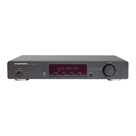
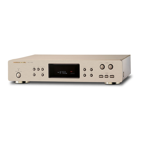
Marantz ST7001/N1S User manual

ST7001
Please use this service manual with referring to the user guide ( D.F.U. ) without fail.
Service
Manual
ST7001
DAB / FM / AM Tuner
ST7001 /N1B/N1S
Part no. 90M46BW855010
First Issue 2005.08
MZ
TABLE OF CONTENTS
SECTION PAGE
1. TECHNICAL SPECIFICATIONS ........................................................................................... 1
2. FACTORY / SERVICE MODE ............................................................................................... 2
3. WRITING MAIN MICROPROCESSOR PROCEDURE ......................................................... 3
4. UPDATE DAB MICROPROCESSOR PROCEDURE .......................................................... 12
5. WIRING DIAGRAM .............................................................................................................21
6. BLOCK DIAGRAM ..............................................................................................................23
7. SCHEMATIC DIAGRAM...................................................................................................... 25
8. PARTS LOCATION.............................................................................................................. 29
9. MICROPROCESSOR AND IC DATA................................................................................... 35
10. EXPLODED VIEW AND PARTS LIST ................................................................................. 43
11. ELECTRICAL PARTS LIST................................................................................................. 46
PUSH ENTER
PUSH ENTER
TUNING/PRESET
TUNING/PRESET
STEREO
STEREO
RDS
RDS
TUNED
TUNED
SECONDARY
SECONDARY
BAND SELECT
BAND SELECT
AUTO TUNE
AUTO TUNE
MENU
MENU
DISPLAY
DISPLAY
DIMMER
DIMMER
STANDBY
STANDBY
ON/STANDBY
ON/STANDBY
POWER
POWER
DAB/FM/AM TUNER ST7001

MARANTZ DESIGN AND SERVICE
Using superior design and selected high grade components, MARANTZ company has created the ultimate in stereo sound.
Only original MARANTZ parts can insure that your MARANTZ product will continue to perform to the specifications for which
it is famous.
Parts for your MARANTZ equipment are generally available to our National Marantz Subsidiary or Agent.
ORDERING PARTS :
Parts can be ordered either by mail or by Fax.. In both cases, the correct part number has to be specified.
The following information must be supplied to eliminate delays in processing your order :
1. Complete address
2. Complete part numbers and quantities required
3. Description of parts
4. Model number for which part is required
5. Way of shipment
6. Signature : any order form or Fax. must be signed, otherwise such part order will be considered as null and void.
SHOCK, FIRE HAZARD SERVICE TEST :
CAUTION : After servicing this appliance and prior to returning to customer, measure the resistance between either primary AC
cord connector pins ( with unit NOT connected to AC mains and its Power switch ON ), and the face or Front Panel of product and
controls and chassis bottom.
Any resistance measurement less than 1 Megohms should cause unit to be repaired or corrected before AC power is applied, and
verified before it is return to the user/customer.
In case of difficulties, do not hesitate to contact the Technical
Department at above mentioned address.
050616MZ
USA
MARANTZ AMERICA, INC
1100 MAPLEWOOD DRIVE
ITASCA, IL. 60143
USA
PHONE : 630 - 741 - 0300
FAX : 630 - 741 - 0301
JAPAN
Technical
35- 1, 7- CHOME, SAGAMIONO
SAGAMIHARA - SHI, KANAGAWA
JAPAN 228-8505
PHONE : +81 42 748 1013
FAX : +81 42 741 9190
EUROPE / TRADING
MARANTZ EUROPE B.V.
P. O. BOX 8744, BUILDING SILVERPOINT
BEEMDSTRAAT 11, 5653 MA EINDHOVEN
THE NETHERLANDS
PHONE : +31 - 40 - 2507844
FAX : +31 - 40 - 2507860
AUSTRALIA
QualiFi Pty Ltd,
24 LIONEL ROAD,
MT. WAVERLEY VIC 3149
AUSTRALIA
PHONE : +61 - (0)3 - 9543 - 1522
FAX : +61 - (0)3 - 9543 - 3677
NEW ZEALAND
WILDASH AUDIO SYSTEMS NZ
14 MALVERN ROAD MT ALBERT
AUCKLAND NEW ZEALAND
PHONE : +64 - 9 - 8451958
FAX : +64 - 9 - 8463554
THAILAND
MRZ STANDARD CO., LTD
746 - 754 MAHACHAI ROAD.,
WANGBURAPAPIROM, PHRANAKORN,
BANGKOK, 10200 THAILAND
PHONE : +66 - 2 - 222 9181
FAX : +66 - 2 - 224 6795
TAIWAN
PAI- YUING CO., LTD.
6 TH FL NO, 148 SUNG KIANG ROAD,
TAIPEI, 10429, TAIWAN R.O.C.
PHONE : +886 - 2 - 25221304
FAX : +886 - 2 - 25630415
MALAYSIA
WO KEE HONG ELECTRONICS SDN. BHD.
2ND FLOOR BANGUNAN INFINITE CENTRE
LOT 1, JALAN 13/6, 46200 PETALING JAYA
SELANGOR DARUL EHSAN, MALAYSIA
PHONE : +60 - 3 - 7954 8088
FAX : +60 - 3 - 7954 7088
KOREA
MARANTZ KOREA CO., LTD.
ROOM 604, ELECTRO OFFICE, 16-58,
HANGGANG-RO 3GA, YONGSAN-KU,
SEOUL, 140-013, KOREA
PHONE : +82 - 2 - 323 - 2155
FAX : +82 - 2 - 323 - 2154
SINGAPORE
WO KEE HONG DISTRIBUTION PTE LTD
No.1 JALAN KILANG TIMOR
#08-03 PACIFIC TECH CENTRE
SINGAPORE 159303
PHONE : +65 6376 0338
FAX : +65 6376 0166
CANADA
MARANTZ CANADA INC.
5-505 APPLE CREEK BLVD.
MARKHAM, ONTARIO L3R 5B1
CANADA
PHONE : 905 - 415 - 9292
FAX : 905 - 475 - 4159
D&M Holdings Inc.
1
1. TECHNICAL SPECIFICATIONS
FM tuner section
Frequency range.................... 87.5 MHz ~ 108.0 MHz[/N]
Antenna terminals............................... 75 Ω, Unbalanced
Usable sensitivity .................................. 1.1 µV (12.2 dBf)
..........................................1.1 µV (IHF)
Image interference ratio .......................................... 80 dB
IF interference ratio............................................... 100 dB
AM suppression ratio .............................................. 50 dB
Effective selectivity............................... 50 dB (±400 kHz)
Capture ratio .......................................................... 2.0 dB
Frequency characteristics .... 20 Hz ~ 15 kHz +0.5/1.0 dB
Signal-to-noise ratio
Monaural .............................74 dB (IHF), 70 dB (DIN)
Stereo..................................68 dB (IHF), 64 dB (DIN)
Total harmonic distortion
Mono 1 kHz (at 75 kHz dev.) ............................. 0.2 %
Stereo 1 kHz (at 67.5 kHz dev.) ........................ 0.3 %
Stereo separation 1 kHz (WIDE)............................. 43 dB
DAB tuner section [/N version only]
Frequency range
.......... 174.928 (5A) ~ 239.200 (13F) MHz (BAND III)
........1452.960 (LA) ~ 1490.624 (LW) MHZ (L.BAND)
Sensitivity. ...........................................................-99 dBm
Signal-to-noise ratio.............................................. 103 dB
THD+N....................................................0.007 % (1 kHz)
Channel separation.................................. 100 dB (1 kHz)
Selectivity............................. 40 dB (at adjacent channel)
Frequency response ............+0.5/0.5 dB (5 Hz ~ 20 kHz)
Digital output........................................... Optical, Coaxial
Sampling frequency .............................................. 48 kHz
Aerial terminal...........................................75 Ω, F female
Analog output level ............................................... 2 Vrms
AM tuner section
Frequency range......................... 522 kHz ~ 1611kHz[/N]
Antenna terminals..........Terminal type with loop antenna
Usable sensitivity .................................................... 18 µV
Signal-to-noise ratio................................................ 53 dB
General
Power supply.....................................AC 230 V, 50 Hz[/N]
Power consumption.................................................. 12 W
Weight.....................................................................4.1 kg
Accessories
Audio connecting cord ................................................... 1
Power supply cord.......................................................... 1
Remote control unit (RC7001ST) .................................. 1
Size "AAA" batteries ...................................................... 2
AM loop antenna............................................................ 1
FM indoor antenna......................................................... 1
DAB indoor antenna..................................................1[/N]
Remote Control Connecting Cord.................................. 1
User Guide..................................................................... 1
PUSHENTERPUSHENTER
TUNING/PRESETTUNING/PRESET
STEREOSTEREO
RDSRDS
TUNEDTUNED
SECONDARYSECONDARY
BANDSELECTBANDSELECT
AUTOTUNEAUTOTUNE
MENUMENU
DISPLAYDISPLAY
DIMMERDIMMER
STANDBYSTANDBY
ON/STANDBYON/STANDBY
POWERPOWER
DAB/FM/AM TUNER ST7001DAB/FM/AM TUNER ST7001
1233315
360
440
(mm)
13 65
78

2
2. FACTORY / SERVICE MODE
A. FACTORY MODE
To reset all settings to default status, follow the procedure
below.
1. Connect mains cord to the unit while pressing DIMMER
and DISPLAY button. (DIMMER and DISPLAY button are
pushed 3 seconds or more.)
2. The unit becomes the setup of default automatically.
B. SERVICE MODE
Micromrocessor and DAB software Version check
1) Connect mains cord to the unit while pressing MENU and
DISPLAY button.
2) All Segments of FLD will be light ON.
3) Turn TUNING/PRESET Knob clockwise or counter
clockwise. VIRSION is displayed on FLD.
Ex. :
4) To exit Service mode, turn off the power switch and
disconnect mains cord.
A. FACTORY
モード
モード
1. DIMMER ボタンと DISPLAY ボタンを押しながら電源コー
ドを接続します。約3秒以上ボタンを押します。
2. 自動的に出荷時の設定になります。
B. SERVICE
モード
モード
Microprocessor とDAB software VERSION 確認
1) MENU ボタンと DISPLAY ボタンを押しながら電源コード
を接続します。
2) FLD が全点灯します。
3) TUNING/PRESET ツマミを回転させると各バージョンが表
示されます。
表示例 :
4)サービスモードの解除は、電源を切り電源コードを外します。
Main Microprocessor VERSION
DAB Software VERSION

3
NECESSARY EQUIPMENT
• Windows PC (OS : Windows2000 or WindowsXP) with
Serial Port
• RS-232C Cable straight type (9 Pin male - 9 Pin female)
• Connection JIG : ST-7001 DAB/MICOM UPGRADE
BOARD (90M-ST7001JIG)
• Writing software (flashprog16lx-v01l11.exe)
• Writing data (Marantz_DABxxxx.mhx)
NOTE: xx is a revision number.
INSTALL PROCEDURE
Double click flashprog16lx-v01l11.exe.
3. WRITING MAIN MICROPROCESSOR
PROCEDURE
必要機器
• Windows PC (OS : Windows2000 または WindowsXP) で
Serial ポートのあるもの
• RS-232C ストレートケーブル (9Pin オス -9Pin メス )
• 接続冶具 : ST-7001 DAB/MICOM UPGRADE BOARD
(90M-ST7001JIG)
• 書き込み用ソフトウェア (flashprog16lx-v01l11.exe)
• 書き込み用データ (Marantz_DABxxxx.mhx)
インストール手順
flashprog16lx-v01l11.exe をダブルクリックします。

4
Click Yes.
Click Next.
Yes をクリックします。
Next をクリックします。

5
Check Complete, and click Next.
Click Install.
Complete にチェックを入れて Next をクリックします。
Install をクリックします。

6
The status bar appears.
Click Finish.
インストールが開始します。
Finish をクリックします。

7
WRITING PROCEDURE
Disconnect the mains cord from the unit.
Connect RS-232C on the connection JIG and Serial Port of
windows PC with RS-232C cable.
Turn the MODE SELECTOR switch (SW401) of Connection
JIG to the MICOM UPGRADE side.
Connect the connection JIG to SERVICE PORT in the rear
panel of the unit.
Connect mains cord to the unit.
Launch up the FUJITSU Flash MCU Programmer
(FMC16LX).
Connection
Click Start, programs, FUJITSU FLASH MCU Programmer
and FMC16LX.
書き込み手順
本機の電源ケーブルを抜きます。
Windows PC のSerial Port と接続冶具を RS-232C ケーブル
で接続します。
接続冶具の MODE SELECTOR スイッチ (SW401) をMICOM
UPGRADE 側に切替えます。
接続冶具を本体のリアパネルにある SERVICE PORT に接続し
ます。
本体の電源ケーブルを差し込みます。
接続図
Start →programs →FUJITSU FLASH MCU Programmer
→FMC16LX をクリックして起動します。
Connection JIG :
ST-7001 DAB/MICOM
UPGRADE BOARD
(90M-ST7001JIG)
RS-232C Cable straight type
(9 Pin male - 9 Pin female)
Windows PC
MODE SELECTOR switch (SW401)
MICOM UPGRADE side.

8
Click Set Environment.
Choose the using serial port, and click OK.
Set Environment をクリックします。
接続している Serial Port 番号を選び、OK をクリックします。

9
Choose MB90F352/C/S/CS in Target Microcontroller.
Choose 4MHz in Crystal Frequency.
Click Open.
Select writing data, and click Open.
Target Microcontroller から MB90F352/C/S/CS を選びます。
Crystal Frequency から 4MHz を選びます。
Open をクリックします。
書き込みデータを選び、Open をクリックします。

10
Click Full Operation(D+E+B+P).
Click OK.
Click OK.
Full Operation(D+E+B+P) をクリックします。
OK をクリックします。
OK をクリックします。

11
Click X icon, and close FUJITSU Flash MCU Programmer
(FMC16LX).
Disconnect mains cord from the unit.
Disconnect connection JIG from the unit.
Check the version.
Refer to "2. SERVICE MODE" on page 2.
X(閉じる )アイコンをクリックし終了します。
本体から電源ケーブルを抜きます。
接続冶具を外します。
バージョンを確認してください。
2 ページの "2. SERVICE MODE"で確認します。

12
NECESSARY EQUIPMENT
• Windows PC (OS : Windows2000 or WindowsXP) with
Parallel Port
• Parallel Cable straight type (25 Pin male - 25 Pin female)
• Connection JIG : ST-7001 DAB/MICOM UPGRADE
BOARD (90M-ST7001JIG)
• Writing software and several files (DAB folder: include fast
DRE310 Programmer.exe, install.bat, etc...)
• Writing data (Flash_DRE310_EVMSPISLAVE_ 20050701
_TBK_01_002_HE.bin)
NOTE: File name will change according to release date.
INSTALL PROCEDURE
Press right button of mouse on the install.bat, and choose
the Edit in a menu.
4. UPDATE DAB MICROPROCESSOR
PROCEDURE
必要機器
• Windows PC (OS : Windows2000 または WindowsXP) で
Parallel ポートのあるもの
• Parallel ストレートケーブル (25Pin オス -25Pin メス )
• 接続冶具 : ST-7001 DAB/MICOM UPGRADE BOARD
(90M-ST7001JIG)
• 書き込み用ソフトウェア一式 (DAB フォルダ内 fast
DRE310 Programmer.exe 、install.bat など )
• 書き込み用データ (Flash_DRE310_EVMSPISLAVE_ 2005
0701_TBK_01_002_HE.bin) ファイル名は変更になる場合
があります。
インストール手順
Install.bat を右クリックしメニューを出し、編集 (Edit) を選び
ます。

13
The text which copies "wdpnp.sys" and a "windrvr.sys"
file to the system folder of Windows is described.
Check the following texts. When text is different,
correct it, then save as same filename.
Case of Windows XP
Case of Windows 2000
Click Xicon, and close.
wdpnp.sys とwindrvr.sys ファイルを Windows のシステムフォ
ルダにコピーする文章が書かれています。下記の通りにかかれ
ているか確認してください。
もし、下記と違う場合は違う箇所を書き直し、上書き保存をし
てください。
Windows XP の場合
Windows 2000 の場合
Xアイコンをクリックして閉じます。

14
Double click Install.bat.
Command prompt is launched, and files are copied.
Check that the files have been copied.
Press the Enter or Space button, and command prompt is
closed automatically.
Install.bat をダブルリックします。
コマンドプロンプトが立ち上がりファイルをコピーします。
ファイルがコピーされたことを確認してください。
Enter または Space を押すと、自動的にコマンドプロンプト
が閉じます。

15
WRITING PROCEDURE
Disconnect the mains cord from the unit.
Connect Parallel connector on the connection JIG and
Parallel Port of windows PC with parallel cable.
Turn the MODE SELECTOR switch (SW401) of Connection
JIG to the DAB UPGRADE side.
Connect the connection JIG to SERVICE PORT in the rear
panel of the unit.
Connect mains cord to the unit.
Press the POWER ON/STANDBY button, and turn on the
unit.
Connection
Double click fast DRE310 Programmer.exe.
書き込み手順
本体の電源ケーブルを抜きます。
Windows PC のparallel Port と接続冶具を parallel ケーブルで
接続します。
接続冶具のスイッチ (SW401) をDAB UPGRADE 側に切替え
ます。
接続冶具を本体のリアパネルにある SERVICE PORT に接続し
ます。
本体の電源ケーブルを差込みます。
POWER ON/STANDBY ボタンを押し、本体の電源を入れます。
接続図
fast DRE310 Programmer.exe をダブルクリックします。
Connection JIG :
ST-7001 DAB/MICOM UPGRADE BOARD
(90M-ST7001JIG)
Parallel Cable straight type
(25 Pin male - 25 Pin female)
Windows PC
MODE SELECTOR switch (SW401)
DAB UPGRADE side.

16
DRE310 In System Programmer is launched.
The same name as File Name of DataFlash is displayed.
When a file name is different, change is required for the right
file name.
Check Include this device in DataFlash.
DRE310 In System Programmer が立ち上がります。
DataFlash のFile Name に書かれているファイル名と同一名が
表示されます。
もし、ファイル名と違う場合は正しいファイル
名に変更が必要です。
Include this device にチェックを入れます。

17
Choose Erase in Operation.
Click Execute.
Operation から Erase を選びます。
Execute をクリックします。

18
The data of DAB microprocessor is erased.
Erased OK appears in status.
Choose Program and Verify in Operation.
DAB マイコンのデータが消去されます。
Status にErased OK と表示されます。
Operation から Program and Verify を選びます。
This manual suits for next models
2
Table of contents
Other Marantz Tuner manuals

Marantz
Marantz AV7705 User manual

Marantz
Marantz 110 User manual

Marantz
Marantz ST551 User manual

Marantz
Marantz AV7702 User manual

Marantz
Marantz AV8802A User manual

Marantz
Marantz AV8802 User manual

Marantz
Marantz ST500 User manual

Marantz
Marantz AV7703 User manual

Marantz
Marantz AV9000 User manual

Marantz
Marantz ST4000 User manual

Marantz
Marantz ST400 User manual

Marantz
Marantz AV7701 User manual

Marantz
Marantz AV7702 User manual

Marantz
Marantz ST-55 User manual

Marantz
Marantz 74ST48/01B User manual

Marantz
Marantz AV7703 User manual

Marantz
Marantz ST-15S1 User manual

Marantz
Marantz AV7704 User manual

Marantz
Marantz ST6000 User manual

Marantz
Marantz AV7702mkg User manual