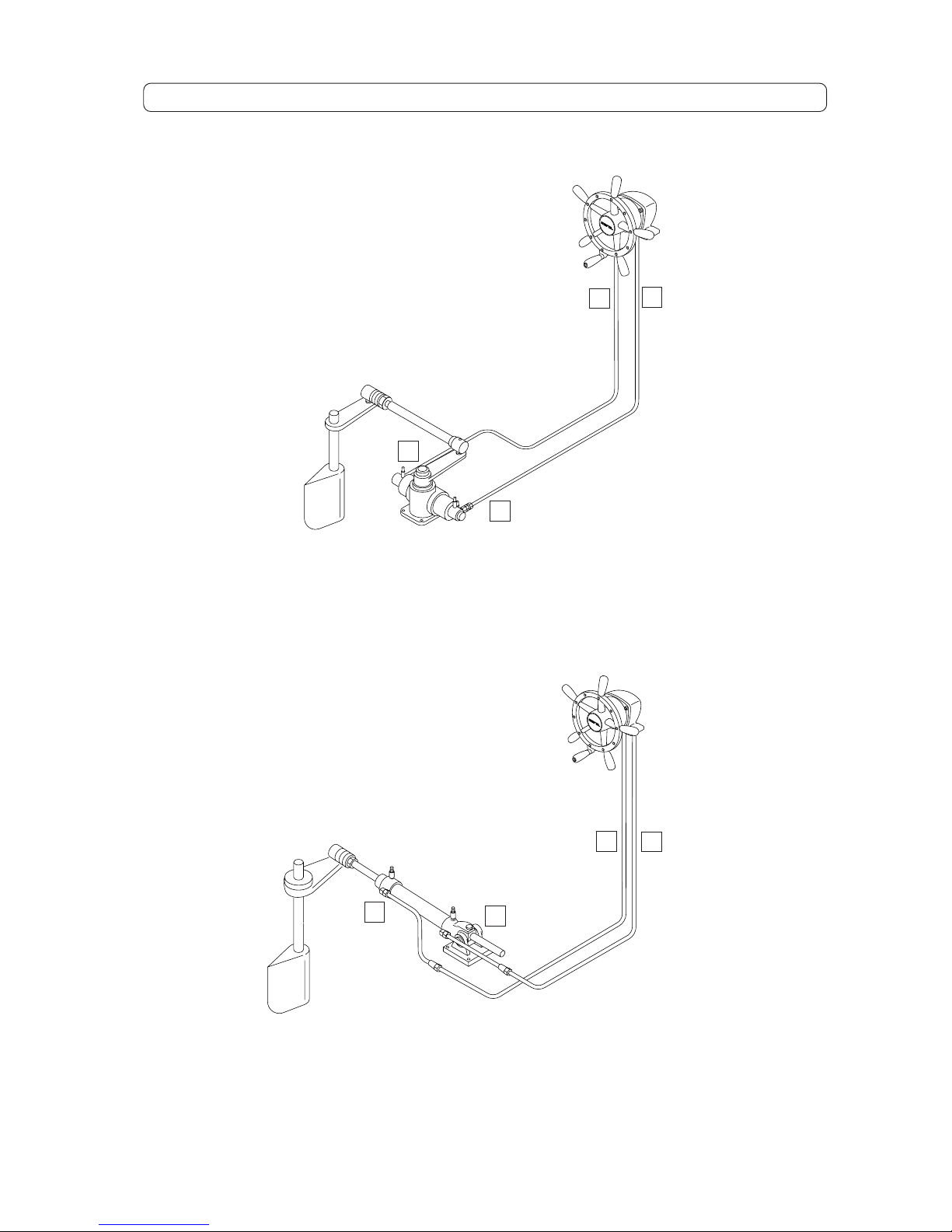
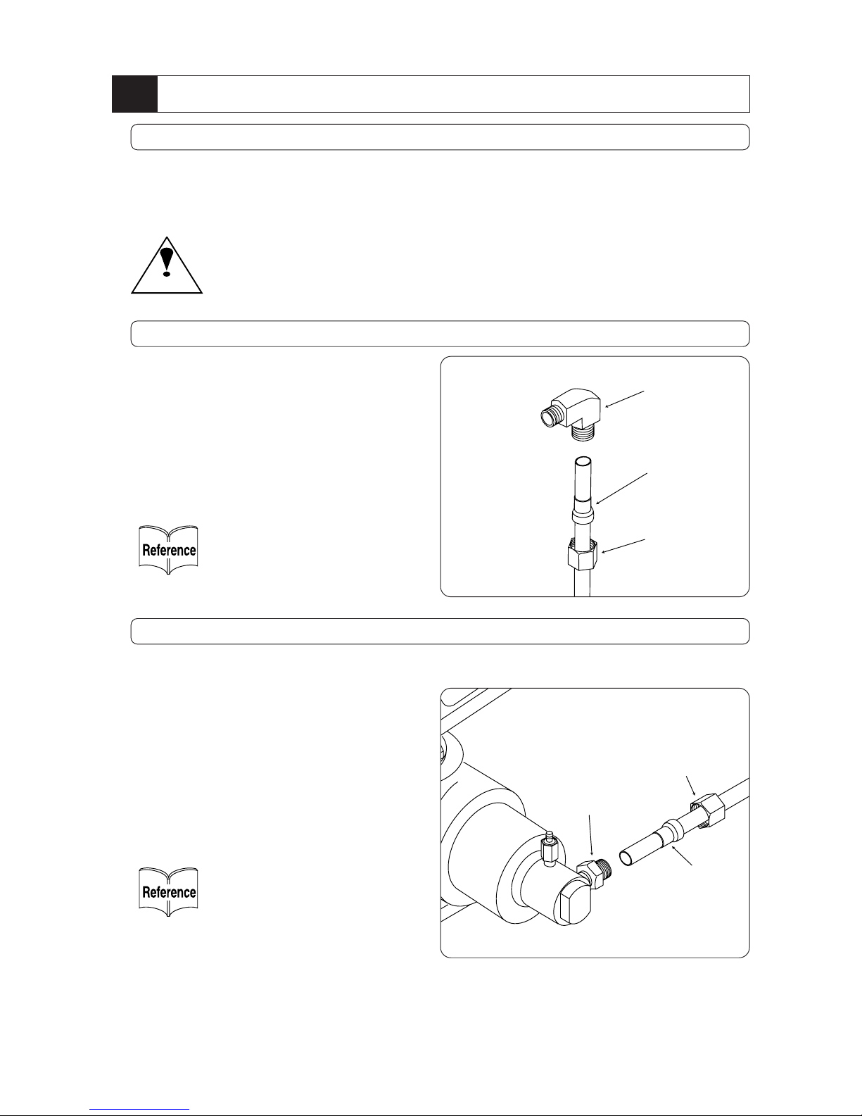
Marol HRP-18-2 User manual

Hydraulic Steering System
MSS
Installation Manual
MB-030200-1E

1
For Safety Precautions - - - - - - - - - - - - - - - - - - - - - - - 2
System Configuration and Parts - - - - - - - - - - - - - 3
Installation of System - - - - - - - - - - - - - - - - - - - - - 5
Hydraulic Piping - - - - - - - - - - - - - - - - - - - - - - - - - 9
Oil Filling and Air Purging- - - - - - - - - - - - - - - - - 11
Piping and Air Purging in case of operation at 2 places
- - - 13
Periodical Inspection and Maintenance- - - - - - - 14
Troubleshooting - - - - - - - - - - - - - - - - - - - - - - - - 15
Drawings- - - - - - - - - - - - - - - - - - - - - - - - - - - - - - - - - 16
~Reference~
Thank you so much for your purchase of Marol Hydraulic Steering System.
This Installation Manual explains installation method of System and the matters to be cared. For full
play of function of this equipment, read this manual carefully and handle the equipment correctly.
Keep this manual at the place where it will not be lost or damaged, and carry it with you whenever you
get on board. If you resale or transfer this equipment to a third party, hand this manual over to new
owner.
~Contents~
1
2
3
4
5
6
7

2
Warning
For Safety Precautions
Precautions when installing and operating Hydraulic Steering System are explained hereunder.
Warning
As to Thunder
When thunderclap is heard, don't touch
any metal parts of equipments.
Induction of thunder is in danger of getting a shock.
As to Use
During normal operation, be sure to
observe all around the boat and watch
the course.
Caution
Caution
As to Piping
Don't use saw when cutting copper
tubes. Once finished piping works,
clean up all around piping and flush
connectors once removed.
Sawdust and/or fins by saw cutting
may cause poor operation.
Be sure to use pipe cutter and cut the
edges at right angle.
As to Periodical Inspection
Inspect or maintain all the equipment periodically.
Inspection and maintenance should be done periodi-
cally in accordance with Installation Manual.
WARNING shows the assumptive details which may lead
to the possibilities of death or serious injury.
CAUTION shows the assumptive details which may lead
to the possibilities of injury or damage of materials.
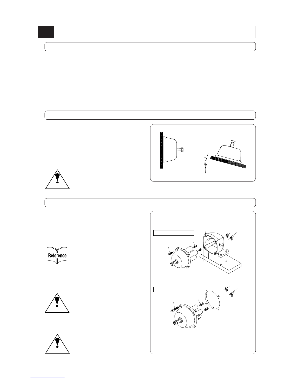
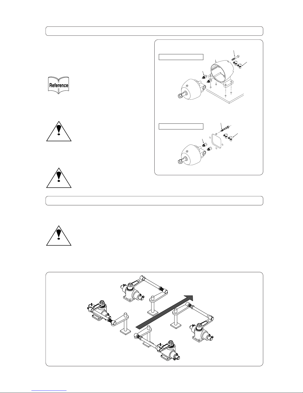
As to Helm Pump
Don't install it at the places where it may disturb
the steering.
Accidents may occur, if it will be installed at the
places where it may impede front visibility and
disturb steering.
On the fitting surface, apply caulking materials, if
necessary.
This is for prevention against penetration of
water into inside of boat.
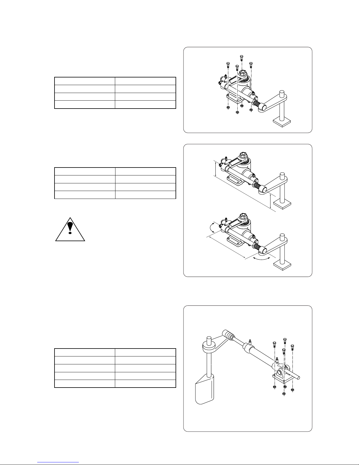
As to Receiving Cylinder Direct-driving type
Install Receiving Cylinder and connect-
ing link of tiller on even level with same
height.
If the connecting link is listed, it may
drop during steering.
Be sure to fasten the locknuts of cylinder
tightly.
After installation or stroke adjustment,
be sure to fasten locknuts tightly.
Otherwise it may cause the falling down
of cylinder.
As to Receiving Cylinder Rotary type
Install Receiving Cylinder and connect-
ing link of tiller on even level with the
same height. If the connecting link is
listed, it may drop during steering.
As to Inspection before Sailing Out
Before sailing out, operate handle and
confirm it to work normally.
Check oil level.

3
1System Configuration and Parts
Parts List of System Configuration
Cylinder Rotary type Cylinder Direct-driving type
Additional set
S-1850-S1
S-1863-S1
S-3075-S1
S-3875-S1
S-3080-S1
S-3880-S1
S-1835-S1
S-1842-S1
S-2342-S1
S-3042-S1
S-3042L-S1
S-3055L-S1
S-3855L-S1
S-18R-10R
S-23R-12R
S-30R-12R
S-38R-12R
Helm Pump HRP-18-2
Article Model
11 11 1
HRP-23 1 1
HRP-30-2 1 1 1 1 1 1
HRP-38 1 1 1 1
Installing Stand MBF-18-2 1 1 1 1 1 1 1
1111 11 11 11
11 111 11
1111 11 11 11
1
11
11
11
1
111
1
11
11
1111
1
1111
11
1
111
1
11
1
1111
11
2
2
22
2
2
22222 22 22 22
1
1
11
1
1
11111 11 11 11
22
222 22
2
2
22
2
2
22222 22 22 22
2
222
22222 22
22222 22
22222 22
11111111111 11
11111111111 11
11111111111 111111
11111111111 111111
11111111111
S-3842L-S1
1
1
1
1
1
1
1
2
1
2
2
2
2
2
1
1
1
1
1111111
MBF-30-2
Wheel WR-240
WR-340
Cylinder MRB-50A
MRB-63A
MRB-75A
MRB-80A
MSB-35
MS-42
MS-42L
MS-55L
Connector JB-5063
JB-7580
JB-35
JB-42
JB-55
Tiller TA-2835
TA-42
TA-42L
TA-55
TB-2835
Boss
TB-42
TB-55
Copper Tube CUT-10
CUT-12
Accessory Set CL-10SET
CL-12SET
Pipe Fitting KC10-PT1/4
KC12-PT1/4
Elbow Fitting KLN10-PT1/4
KLN12-PT1/4
Trident Fitting KT-10
KT-12
High Pressure Rubber Hose
HRH-S2-S2-610
Hose Adapter BS-3005F04
Elbow BKJ-44
Hydraulic Oil HF-15-3.6Y
Guide for Refueling Hole
OG36
Polyvinyl Chloride Tube
VT-1
Tube exclusive for Refueling
VT-2
Installation Manual
MB-030200-1E

4
System Configuration
Configuration of Rotary type
A
A
B
B
Helm Pump
Cylinder MRB Type (Rotary type)
Configuration of Direct-driving type
A
B
Helm Pump
Cylinder MS Type (Direct-driving type)
A
B

5
2Installation of System
Prior to installing
Do not install equipment to places where
• the spot will be submerged by splashes of seawater and/or rainfall.
• the spot will become difficult in works of inspection, maintenance, piping or else.
• the spot will suffer high temperature under direct sunbeams or close to high temperature pipings.
• the spot will be affected by intensive vibration close to engine or else.
Outline and installing dimensions of each unit are shown on Drawings. Receiving Cylinder must be
installed especially just as shown on Drawings.
Installation of Helm Pump (HRP-18-Ⅱ/HRP-23)
1. Install Helm Pump on the place in bridge or so
where its height is easy to steer. Select steady
position not rickety when steering wheel is
turned.
2. Installing angle can be chosen widely from ver-
tical to nearby horizontal.
15°
Fixing bolts
Adapters
Elbow fittings
Fixing stand
Fitting bolts Adapters
Elbow fittings
In case of Foot mount type
In case of Dashboard mount type
1. Foot mount type or Dashboard mount type
can be installed depending on installing
place. By using template appended at the
end of this manual, drill holes for fixing bolts
and piping, and fix the unit tightly with bolts
and nuts.
Installing Position and Angle of Helm Pump
For installation of Foot mount type, use M8 x 25
bolts. For installation of Dashboard mount type,
use M8 x 45 bolts.
2. Peel off protection plugs of Helm Pump and fit
adapters beforehand, then insert them to
elbow fittings.
3. Once installed Helm Pump, mount wheel to
Helm Pump and fix it with nuts.
Caution
Be sure to install semicircular key along key fit-
ting groove when installing wheel.
Caution
Apply caulking materials to fitting surface, if
necessary, to avoid water penetration into
inside of boat.
Caution
Don't install it at the place where steering is
disturbed. When installing it at such a place
where front visibility is impeded or steering
is disturbed, it may cause damage.

6
Fittingbolts
Adapters
Elbowfittings
Fittingstand
Studbolts
Adapters
Elbowfittings
IncaseofFootmounttype
IncaseofDashboardmounttype
Installation of Helm Pump (HRP-30-Ⅱ/HRP-38)
Installation of Receiving Cylinder
• It is important to install Receiving Cylinder to robust part of the hull, since it may generate large torque to move tiller.
• Upon installing Receiving Cylinder apply waterproof grease sufficiently on receiving portion of joint link, ball joints, etc.
Caution
For installation of Receiving Cylinder, install it in accordance with dimensions of Drawings attached at he end of
this manual.
Bow
•Position of Receiving Cylinder and linkage can be as shown in figure below. Accordingly install it
matching to layout and/or system of the boat.
1. Either Foot mount type or Dashboard mount
type can be installed depending on installing
place. By using template appended at the
end of this manual, drill holes for fixing bolts
and piping, and fix the unit tightly with bolts
and nuts.
For installation of Foot mount type, use M8 x 70
bolts. For installation of Dashboard mount type,
use M8 x 50 bolts.
2. Peel off protection plugs of Helm Pump and fit
adapters beforehand, then insert them to
elbow fittings.
3. Once installed Helm Pump, mount wheel to
Helm Pump and fix it with nuts.
Caution
Be sure to install semicircular key along key fit-
ting groove when installing wheel.
Caution
Apply caulking materials to fitting surface, if
necessary, to avoid water penetration into
inside of boat.

7
• Installation of Cylinder MRB Type (Rotary type)
Keep same height
Max. size
A
90°
90°
1. Drill 4 holes according to the table and install
Cylinder tightly by bolts and nuts to the place
to be installed.
2. Install it by paying attention to dimensions,
positions and angles of the figure.
Caution
Make the same height the connection
link between Receiving Cylinder and
tiller lever, and install it on even level. If
connection link is listed, the connection
link may come off during steering.
• Installation of Cylinder MS Type (Direct-driving type)
1. Drill 4 holes according to the table and install
Cylinder tightly by bolts and nuts to the place
to be installed.
Receiving Cylinder type Diameter of fitting holes
MRB-63A 13mm
MRB-75A 18mm
MRB-80A 18mm
Receiving Cylinder type Max. size A
MRB-63A 400mm
MRB-75A 500mm
MRB-80A 500mm
Receiving Cylinder type Diameter of fitting holes
MSB-35 13mm
MS-42 13mm
MS-42L 13mm
MS-55L 18mm

8
2. Install it with care in installing position and
angle. Once finished the installation of
Cylinder, remove space washer for protec-
tion.
Caution
Confirm that X-X and Y-Y axes remain
parallel at the position where helm
stands neutral. If not parallel, not only
Cylinder becomes not move smoothly,
but also rod may be flawed or bent.
X
X
Y
Y
Space Washer

9
3Hydraulic Piping
Prior to Hydraulic Piping
•Copper tube is to be used for whole piping. Use correct size copper tube shown on Parts List of
System Configuration in page 3.
•Once decided copper tube piping arrangement, cut tube by pipe cutter to the length necessary.
Caution
If tubes are cut by saw, sawdust and/or fins may cause damage of equipment.
Piping to Helm Pump
Elbow fitting
Sleeve
Nut
1. Insert nut and then sleeve to the tip of copper
tube.
Insert tip of copper tube to elbow fitting firmly,
then screw nut by wrench so that sleeve will
be squeezed into it. Screw nut further 3/4-1
rotation from the point beginning to feel heavy
to rotate.
Make sure not to mistake the
direction of sleeve.
Piping to Cylinder
•Piping to Cylinder MRB Type (Rotary type)
Fitting
Sleeve
Nut
1. Connect another end of copper tube to fitting
of Receiving Cylinder.
Insert nut and then sleeve to the tip of copper
tube. Insert tip of copper tube to fitting firmly
and then screw nut by wrench so that sleeve
will be squeezed into it. Screw nut further 3/4-
1 rotation from the point beginning to feel
heavy to rotate.
2. Be sure to connect A port of Helm Pump to A
port of Receiving Cylinder, and B port of
Helm Pump to B port of Receiving Cylinder.
Make sure not to mistake the
direction of sleeve.

10
•Piping to Cylinder MS Type (Direct-driving type)
90°elbow
High pressure rubber hose
Adapter
Pipe fitting
1. High pressure tube is to be used only for
cylinder side, because Cylinder MS Type
(Direct-driving type) shakes interlocking with
steering.
2. Connect copper tube to Receiving Cylinder
through 90° elbow, high pressure hose,
adapter and pipe fitting.
3. Connect copper tube to pipe fitting same as
the case of Cylinder Rotary type.
Completion of Piping
1. Fix piping by metal fitting for piping as shown
in figure.
Fix pipe by metal fitting every 1
meter for strait line and every 30
cm for curving portion.
2. Once completed the piping works, clean up
all around piping, and flush connectors once
removed.
After flushing, reassemble the connectors.
Caution
Be sure that no dust enter the pip-
ing while flushing.
Make sure not to mistake the direc-
tion of sleeve.
4. Be sure to connect A port of Helm Pump to A
port of Receiving Cylinder, and B port of
Helm Pump to B port of Receiving Cylinder.

11
4Oil Filling and Air Purging
1. Firstly, once remove metal fitting connecting
Receiving Cylinder and tiller and make
Receiving Cylinder move at full stroke.
2. Remove filling cap on Helm Pump and fill it
with hydraulic oil.
Caution
At this juncture, make sure that no dust
enter Helm Pump.
Stop bolt tightening bolt
3. Fit attached tube exclusive for oil filling. Fit
tube to Helm Pump side firmly so as not to
suck air. Insert the other end of tube into can
of hydraulic oil so as not to float up from oil
level.
4. Screw in stop valve tightening bolt (M6 x 25
bolt with hexagonal hole) about 6 rotations
until stop it and lastly tighten it lightly by
wrench up to 10 degree.
Preparation of air purging
Air purging plug
of A port side
Air purging plug
of B port side
Polyvinyl chloride tube
for air purging
Air purging plug
of A port side
Air purging plug
of B port side
Polyvinyl chloride tube for air purging
Air purging works of A port side
1. Insert attached polyvinyl chloride tube for air
purging to the tip of air purging plug of A port
side of Receiving Cylinder. When can of
receiving hydraulic oil is provided, release air
purging plug of A port side.
(Don't release plug of B port side yet.)
2. Turn wheel clockwise continuously at the
speed of 1 rotation per sec. When turning 3~4
rotations, oil level will go down but hydraulic
oil will be filled automatically through oil filling
tube.
3. As soon as clear hydraulic oil comes out con-
stantly without bubble from air purging plug of
A port side, close air purging plug of A port
side.

12
Stop valve
tightening bolt
Air purging works of B port side
1. Release fully remove stop valve tightening
bolt (M6 x 25 bolt with hexagonal hole) of
Helm Pump side and remove it.
Air purging
plug of
A port side;
Air purging plug
of B port side
Air purging plug
of A port side
Air purging plug
of B port side
2. Remove polyvinyl chloride tube for air purging
from A pot side, change it to fit to B port side
and release air purging plug of B port side.
3. After confirmation of correct connection of oil
filling tube between Helm Pump and can of
hydraulic oil, turn wheel anti-clockwise slowly
but continuously.
4. As soon as clear hydraulic oil comes out con-
stantly without bubble from air purging plug of
B port side, close air purging plug of B port
side.
5. When wheel works smoothly by operating
from side to side after completion of air purg-
ing works, remove oil filling tube and close fill-
ing cap tightly. Further works will finish by re-
connecting Receiving Cylinder and tiller as it
was.
Last of all, check oil leakage from every unit
and pipe fitting section.
In case of reverse connection, name-
ly connection between A port of
Helm Pump and B port of Receiving
Cylinder, or B port of Helm Pump and
A port of Receiving Cylinder for con-
venience of installation space of
Receiving Cylinder, conduct air purg-
ing works by replacement of A port
with B port of Receiving Cylinder.

13
5In case of steering at 2 places
Piping for steering at 2 places
•Hydraulic Steering System can be operated at 2 places by additional installation of Helm Pump. Even
in this case, working load of wheel operation does not change.
Trident fitting
1. After decision of installing location of Helm
Pumps, cut copper tubes by pipe cutter con-
sidering piping arrangement.
2. Connect A to A, B to B of both Helm Pumps
correctly using trident fitting as per right side
drawing.
3. After piping works, conduct flushing and fixing
of copper tubes same as steering at 1 place.
Air purging of steering at 2 places
Helm Pump of high side
(far side from Receiving Cylinder);
Helm Pump of low side
(near side to Receiving Cylinder)
1. Fill Helm Pump of low side (or near side to
Receiving Cylinder) with hydraulic oil and
close filling cap tightly.
2. Purge air from Helm Pump of high side (or far
side from Receiving Cylinder). Air purging
procedure is same as Clause 11~12.
3. At next step, purge air from Helm Pump of
low side (or near side to Receiving Cylinder).
4. For further perfect air purging, remove oil fill-
ing cap of Helm Pump of high side (or far side
from Receiving Cylinder) and repeat turning
of wheel from side to side at full stroke sever-
al times. Air will return to tank gradually.

14
6Periodical Inspection and Maintenance
•For prevention against damage or troubles of System, routine inspection and periodical maintenance
are necessary. When abnormal condition is found on inspection, immediately repair it or keep it in
good condition.
Item Period Contents
Inspection of oil
quantity
Daily for 10 days after
installation and every
10 days thereafter.
During dead ship, after turning wheel slowly 1~2 rotation
from side to side at neutral position, open oil filling cap and
inspect hydraulic oil. If reduced, refill with oil immediately.
(Recommended hydraulic oil: ISO VG15 equivalent)
Inspection of oil
leakage
Daily for 10 days after
installation and every
10 days thereafter.
Inspect oil leakage from pipe fitting section, Helm Pump,
shaft of Receiving Cylinder or so.
If leakage is found, repair the spot immediately.
Additional
tightening
Daily for 10 days after
installation and every
10 days thereafter.
Tighten additionally fitting bolts and nuts of Helm Pump,
Receiving Cylinder and pipe fitting section.
Supplementation
of grease
Every 1 month Supplement of grease to ball joints and connecting pins of
metal fitting between Receiving Cylinder and tiller.

15
7Troubleshooting
•When abnormal parts are found, don't use as it is and take suitable countermeasure looking for the
cause. If using under abnormal condition, serious accident may be occurred as the case may be.
Therefore, when no solution found by the following table, contact our agent or our company.
Symptom Cause Countermeasure
Wheels are vacillating and
rudder does not work
correctly.
Steering is out of control.
Purge air again.
Repair leaking spot of connecting section and/or
piping, refill with oil and purge air again.
Refill with hydraulic oil and purge air again.
Wheel turning is heavy and
power is needed.
Malfunction of wheel shaft.
Shortage of hydraulic oil
viscosity.
Clogging of filter of
Helm Pump.
Repair and/or lubricate.
Replace to genuine hydraulic oil. (ISO VG15
equivalent)
Rinse or replace filter.
Receiving Cylinder does
not work when turning
wheel.
Dust to suction valve inside
of plunger of Helm Pump.
Malfunction of lock
valve of Helm Pump.
Overhaul and rinse.
Overhaul and rinse, or replace.
Receiving Cylinder returns even
when wheel is suspended.
Malfunction of lock
valve of Helm Pump.
Overhaul and rinse, or replace.
In case of steering at 2
places, while rotating Helm
Pump of one side, Helm
Pump of the other side also
rotates.
Malfunction of lock
valve of Helm Pump.
Dust to check valve of
Helm Pump.
Overhaul and rinse, or replace.
Overhaul and rinse.
Air purging remains imperfect.
Leakage of hydraulic oil.
Shortage of hydraulic oil
inside of oil tank.

16
Drawings
•Wheel (WR-240)
80 34
22
136
80
135
70
•Wheel (WR-340)
70
190
22
5980
139
80
Weight 2.6kg
Weight 3kg

17
•Helm Pump (HRP-18-2F / HRP-23F)
142
24.5 24.5
14
143
9
3
2-Rc1/4
(PT1/4)
A,B PORTS
4
M6
30 82
160
211
51
WOODRUFF KEY
3/16-3/4
1/12 TAPER
72
168
140 4-φ11
50
78
•Helm Pump (HRP-18-2D / HRP-23D)
Model Displacement
Max. pressure Test pressure Tank capaci
ty Weight
HRP-18-2F 18cc/rev 7.8MPa
(80kgf/cm2)
15.7MPa
(160kgf/cm2)
318cc 4.3kg
HRP-23F 23cc/rev
90.5 4-φ9
4-φ9
PCD 146
PCD146
142
24.5 24.5
3
2-Rc1/4
(PT1/4)
9
φ122
A,B PORTS
M6
67.5
20 78 66 51
195
46 12
φ126
WOODRUFF KEY
3/16-3/4
1/12 TAPER
φ124
Model Displacement
Max. pressure Test pressure Tank capaci
ty Weight
HRP-18-2D 18cc/rev 7.8MPa
(80kgf/cm2)
15.7MPa
(160kgf/cm2)
318cc 3.7kg
HRP-23D 23cc/rev

18
•Helm Pump (HRP-30-2F / HRP-38F)
•Helm Pump (HRP-30-2D / HRP-38D)
120
100
28.5 28.5
8
120
4-8M
2-Rc1/4
M6 56
20 68 90.5 51
209.5
20
WOODRUFF KEY
3/16-3/4
14 X 2
1/12 TAPER
4-φ9
102
120
R15
φ148
φ148
151
8
12
28.5 28.5
M6
A,B PORTS
2-Rc1/4
(PT1/4)
42 82 51
1/2 TAPER
14 X 2
WOODRUFF KEY
229
219
10
3/16-3/4
160
188
4-φ11
60
88
Model Displacement
Max. pressure Test pressure Tank capaci
ty Weight
HRP-30-2F 30cc/rev 7.8MPa
(80kgf/cm2)
15.7MPa
(160kgf/cm2)
460cc 5.2kg
HRP-38 38cc/rev
Model Displacement
Max. pressure Test pressure Tank capaci
ty Weight
HRP-30-2F 30cc/rev 7.8MPa
(80kgf/cm2)
15.7MPa
(160kgf/cm2)
460cc 4.9kg
HRP-38 38cc/rev

19
•Receiving Cylinder Rotary type (MRB-50A / 63A / 75A / 80A)
L1
L3
L5
L4
L2
H
•Receiving Cylinder Direct-driving type (MSB-35) (MS-42 / 42L / 55L)
L5
L4
L1
H
L2
L3
Model L1 L2 L3 L4 L5 H
MRB-50A 314 165 105 200 400 185
MRB-63A 364 170 120 200 400 205
MRB-75A 426 221 146 250 500 245
MRB-80A 478 250 170 300 500 281
Working
angle
90°
Oil quanti-
ty needed
77cc
154cc
317cc
395cc
Max. pressure
7.8MPa
(80kgf/cm2)
Test pressure
15.6MPa
(160kgf/cm2)
Weight
13kg
18kg
35kg
51kg
Breaking
torque
392N-m
(40kgf-m)
785N-m
(80kgf-m)
1569N-m
(160kgf-m)
1961N-m
(200kgf-m)
Model L1 L2 L3 L4 L5 H Breaking
torque
Working
angle
Oil quanti-
ty needed Max. pressure Test pressure Weight
MSB-35 779 110 140 155 643 145 637N-m
(65kgf-m)90° 146cc
7.8MPa
(80kgf/cm2)
15.6MPa
(160kgf/cm2)
7.8kg
MS-42 807 105 140 150 670 147 918N-m
(100kgf-m)90° 221cc 15kg
MS-42L 982 140 140 200 776 147 1275N-m
(130kgf-m)90° 291cc 16kg
MS-55L 1033 140 150 200 868 148 2250N-m
(230kgf-m)86° 482cc 22kg
This manual suits for next models
37
Table of contents