MARINE DATA MD69/24 User manual

USER MANUAL MD69/24
PELORUS PEDESTAL BEARING COMPASS REPEATER
F069124
MD69-24-MA-v06r02
2022-01-31
ENGLISH


MD69/24
3
CONTENTS
1 MD69/24 PELORUS PEDESTAL BEARING REPEATER ASSEMBLY ............................ 4
2 DOCUMENT............................................................................................................. 5
2.1 About This Manual ......................................................................................................... 5
3 NOTICE ................................................................................................................... 6
3.1 Copyright......................................................................................................................... 6
4 DESCRIPTION.......................................................................................................... 7
5 SPECIAL FEATURES ................................................................................................ 7
6 MAJOR DIMENSIONS .............................................................................................. 8
6.1 Pelorus Pedestal Assembly........................................................................................... 8
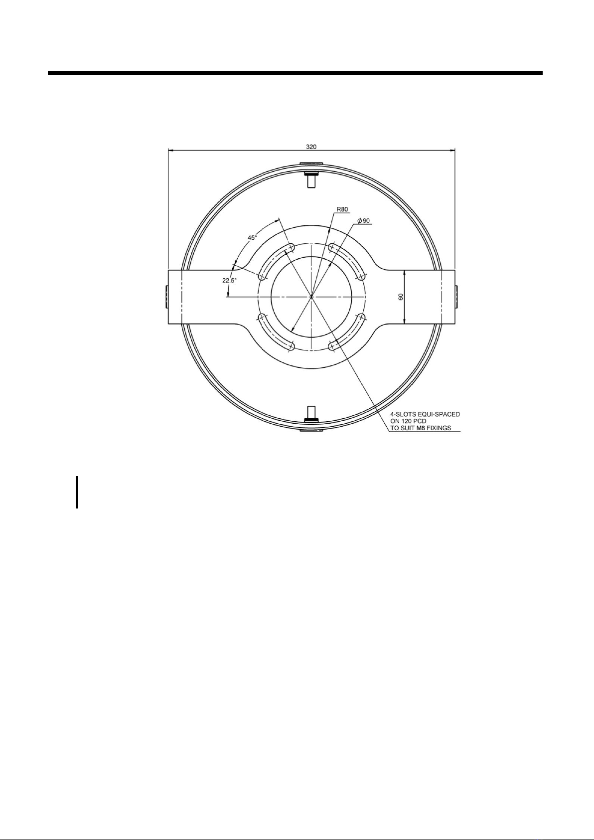
6.2 Bearing Repeater Mounting Dimensions...................................................................... 9
7 INSTALLATION.......................................................................................................10
7.1 Parts List ....................................................................................................................... 10
7.2 Fitting the unit............................................................................................................... 10
7.3 Junction Box Terminal Connections........................................................................... 11
7.4 Junction Box Terminal Configurations ....................................................................... 11
7.5 Junction Box Wiring Diagram...................................................................................... 12
7.6 Junction Box Dimensions ............................................................................................ 12
8 COMMISSIONING THE SYSTEM .............................................................................13
8.1 Product Registration .................................................................................................... 13
9 OPERATION............................................................................................................14
9.1 Dimming Control .......................................................................................................... 14
10 MAINTENANCE AND FAULT-FINDING...................................................................15
10.1 Maintenance ............................................................................................................... 15
10.2 Fault-Finding ............................................................................................................... 15
10.2.1 Repeater does not operate ........................................................................... 15
10.2.2 Repeater aligns to zero degrees but does not follow the source heading... 15
10.2.3 Repeater Display Illumination not functioning ............................................. 15
10.2.4 Dial oscillating +/- 35 degrees...................................................................... 15
10.3 Technical Support ...................................................................................................... 16
10.4 Reporting a Fault ........................................................................................................ 16
11 SPECIFICATIONS..................................................................................................17
12 SPARE PARTS AND ACCESSORIES.......................................................................19
13 GROUNDING AND SHIELDING...............................................................................21
14 SAFETY AND SECURITY .......................................................................................21
15 GLOSSARY OF TERMS..........................................................................................22
16 ABOUT MARINE DATA..........................................................................................23

MD69/24
4
MD69/24 PELORUS PEDESTAL BEARING REPEATER
ASSEMBLY
MD24 Pelorus Pedestal
SKU: CM89124
MD96JCB Weatherproof Junction Box
SKU: F096001
MD69BR Trunnion Mount Bearing Compass Repeater
SKU: F069018

MD69/24
5
1DOCUMENT
1.1 About This Manual
This Manual provides installation, operating Instructions and fault-finding procedures for the
Marine Data MD69/24 Pelorus Pedestal.
After installation, this manual should remain with the vessel to which it relates.
This manual may also be made available in electronic Portable Document Format (PDF). In PDF
format, the following categories are all enabled as active hyperlink references: (1) The titles of
each section; (2) document cross-references; (3) the table of contents.
This document may therefore be navigated quickly and effectively by using a mouse or other
pointing device to activate each of these hyperlinks. This is a printer friendly document, designed
to be printed 2-sided as a booklet with A5 pages on A4 stock paper.
Document name:
Date:
Details:
Author:
MD69-24-MA-v06r01
2021-11-18
First Issue
TSI
MD69-24-MA-v06r02
2022-01-31
Updated SKUs, MD96JCB, Renders, orthographics
TSI

MD69/24
6
2NOTICE
2.1 Copyright
The copyright and all rights of a like nature in respect of this publication in any part of the world
are the property of Marine Data Systems Ltd. (Marine Data).
No part of this document may be reproduced or transmitted in any form or by any means, whether
electronic, mechanical, photocopying, recording or otherwise, nor stored in any information
retrieval system of any kind, nor used for tendering or manufacturing, nor communicated to any
other person without the written permission of Marine Data.
The recipient of this document, as its registered holder, must exercise due diligence in ensuring
that the above conditions are observed (Errors and Omissions Excepted).
Any enquiries relating to this document or its contents should be addressed, in writing, in the first
instance to Marine Data.
MARINE DATA SYSTEMS LIMITED
Vittlefields Technology Centre
Forest Road
NEWPORT
Isle of Wight
PO30 4LY
UNITED KINGDOM
tel: +44 (0)1983 822180
email:
MARINE DATA SYSTEMS LIMITED reserves the right to make changes to its products and
specifications without notice

MD69/24
7
3DESCRIPTION
The MD69/24 is a complete Pelorus Pedestal assembly which houses the Marine Data MD69BR
series of Bearing Repeater with a fully gimballed mounting. It can be deck mounted on a bridge,
externally mounted on wing stations or on the fly bridge and is fully sealed to IEC 60945 Exposed
Area Classification.
When used in conjunction with the Marine Data MD69AZI Azimuth Sight, the MD69BC Bearing
Circle or the MD60A2K Telescopic Marine Alidade it provides the ideal platform for taking
compass bearings.
The MD69/24 Pelorus Pedestal is fitted as standard with a weatherproof MD96JCB Junction Box
for connection to the ship’s cabling (see section 6.3 Junction Box Terminal Connections) can be
expanded up to a 32-way connection with additional terminal blocks. A rotary dimmer control
switch adjusts the background illumination of the installed MD69BR Bearing Repeater.
The MD69/24 Pelorus Pedestal Assembly from Marine Data: Flexible in application, easy to install
and simple to maintain.
4SPECIAL FEATURES
•Aluminium Pelorus Pedestal Bearing Repeater Assembly
•Includes MD69BR Precision Dual-Scale 36:1 Repeater Bowl
•Fully Gimballed Bearing Repeater Mount and
•Includes MD96JCB Weatherproof Terminal Box
•Includes Canvas Protective Cover
•Built-in Dimmer Control
•NMEA 0183 Digital Connection
•Fully sealed to IEC 60945 Exposed Area Classification

MD69/24
8
5MAJOR DIMENSIONS
5.1 Pelorus Pedestal Assembly
All dimensions mm
Bottom View:

MD69/24
9
5.2 Bearing Repeater Mounting Dimensions
All dimensions mm
Note: The Bearing Repeater is to be mounted so that the 000°-180° line of the fixed outer
verge ring is parallel with the ship’s fore-aft centreline.

MD69/24
10
6INSTALLATION
On delivery, carefully inspect the contents of the packing case. Note any damage or any missing
items and ensure that the correct parts are included for your application.
6.1 Parts List
Item:
Description:
No. included:
Part Number:
1
MD69/24 Pelorus Pedestal Assembly
1
F069124
1
MD24 Pelorus Pedestal
1
CM89124
MD69BR Trunnion Mount Bearing Repeater
1
F069018
MD96JCB Weatherproof Junction Box
1
F096001
MD69CPC Canvas Protective Cover
1
F069201
Trunnion Mount Fixings, M8, set of 4
1
CC88776
Base Fixing Bushes, M20, set of 4
1
CM88353
6.2 Fitting the unit
Inspect the mounting position for suitable clearance and cable access. For fixing and foot print
dimensions, refer to section 5 - major dimensions.
Secure the MD69/24 in the chosen mounting position. Identify the vessel’s wiring functions. It is
recommended that a note be made of the vessel’s wiring functions for future reference. Connect
the MD69/24 in accordance with table 6.3 - Junction Box Terminal Connections.
The MD69/24 is designed to use 24 V dc and accept a digital RS422 data signal using the NMEA
0183 protocol. Ensure all incoming supply and signal cables are either suitably insulated and/or
connected, or bonded to the vessel’s earth where appropiate.
Isolation and earthing requirements must comply with Lloyd’s Rules and Regulations VI
paragraph 1.13.2. There is an M6 stud located on the bottom of the juction box for local earth
bonding.
Do not apply power yet.
CAUTION: Application of any voltage other than those stipulated in this product specification
may damage the bearing repeater.

MD69/24
11
6.3 Junction Box Terminal Connections
Terminal:
Type:
Function:
Description:
Repeater
core
colour:
Dimmer
core
colour:
Ships
core
colour:
1
Input
0-24 V
Dimmer
External Dimmer Input:
0 V = Min. illumination.
24 V = Max. illumination
Isolate or connect to supply
negative if not used
PK
GN
2
Input
Positive
+24 V dc Supply
RD
RD
3
Input
Negative
24 V dc Supply Return
WH
BU
4
Input
RDA
NMEA 0183 (IEC 61162-1)
Data Input A
GN
5
Input
RDB
NMEA 0183 (IEC 61162-1)
Data Input B
BU
6
Input
SW_IN
(future
function)
Isolate or connect to supply
negative if not used
BN
7
Output
TDA
NMEA 0183 (IEC 61162-1)
Data Output A (Isolate if not
used)
GY
8
Output
TDA
NMEA 0183 (IEC 61162-1)
Data Output A (Isolate if not
used)
YE
E
Chassis
Chassis
Connection
Screen
SCN
6.4 Junction Box Terminal Configurations
The MD96JCB can be expanded from 16-way, up to a 32-Way connection. Optional additional
Terminal blocks may be secured in the arrangement example below:
Standard 16-way arrangement
Optional 32-way arrangement
Rear Enclosure Front Cover

MD69/24
12
6.5 Junction Box Wiring Diagram
6.6 Junction Box Dimensions

MD69/24
13
7COMMISSIONING THE SYSTEM
Ensure that the installation complies with section 6.2 Fitting the unit
Apply system power (24 V dc) to the MD69/24.
The MD69BR Bearing Repeater will initially align to 000° degrees; it will then adopt the heading
which is being transmitted from the heading source.
Verify that the MD69BR Bearing Repeater follows the heading source when altering the vessel’s
heading, according to the manual for this device.
Ensure that the display lighting is set to a suitable level using the integral rotary dimmer switch.
7.1 Product Registration
Be sure to register your product online at www.marine-data.co.uk.
You will need:
•Product Type (e.g. MD69/24)
•Product Serial No.
•Vessel on which the product is installed
•Installation Date
•Installer / Customer representative contact details
It would also be helpful to list other manufacturer’s equipment to which the product is connected.
(e.g. Gyro, Radar, other Repeaters etc.)
Alternatively, fill out the product registration form and return it to Marine Data .
NOTE: It is the process of registration which activates the warranty.

MD69/24
14
8OPERATION
8.1 Dimming Control
View looking from beneath MD69BR Bearing Repeater.
Rotational Dimming Knob:
•Turn Clockwise to increase dial brightness
•Turn anti-clockwise to reduce dial brightness

MD69/24
15
9MAINTENANCE AND FAULT-FINDING
9.1 Maintenance
No scheduled maintenance is required. It is recommended to gently wipe away any accumulated
dust or periodically wiped with fresh water if located externally.
9.2 Fault-Finding
9.2.1 Repeater does not operate
It is probable that there is a loss of power. Check the dc power supply and data connection to the
unit.
9.2.2 Repeater aligns to zero degrees but does not follow the source heading
The NMEA 0183 digital signal to the repeater is either not present, or the data sentence being
sent is not of the correct structure. Check the heading source data for the presence of a valid
heading data sentence.
9.2.3 Repeater Display Illumination not functioning
If remotely controlled, an incorrect control signal may be being received, check wiring and signals.
The internal LED illumination devices may be damaged or there may be damage to the PCB or
rotary dimmer switch. Return the unit to Marine Data for servicing. It should be noted that the
display illumination may not be noticeable under bright ambient light conditions. Illumination is
controlled independently by the integral rotary dimmer control and the Remote Dimmer input, if
fitted, whichever input is adjusted will take precedence.
9.2.4 Dial oscillating +/- 35 degrees
Check NMEA data connection and validity.
Note: The MD69BR is a sealed unit and has no user-serviceable parts inside. Breaking the
factory seal will invalidate the warranty.

MD69/24
16
9.3 Technical Support
If further technical support is required then please contact your local Marine Data agent or Marine
Data Technical Support:
•By email: support@marine-data.co.uk
•Through our website: www.marine-data.co.uk
All technical support enquiries must include the following basic equipment information:
About your Marine Data Equipment:
1
Marine Data Equipment Model number (e.g. MD69/24)
2
Marine Data Equipment serial number
3
Marine Data Equipment batch code number
4
Details of firmware version (if available)
9.4 Reporting a Fault
If you suspect that your equipment has a fault, please be sure to include as much information
about the fault as possible. The following information checklist shows the additional information
which we will require to process a fault enquiry:
About the suspect fault:
1
Describe the signs that suggest there is a fault condition
2
Describe when and how often the fault occurred. Was this coincidental with the operation of
other equipment or procedures?
3
Describe the indications and the alarm status when the fault occurs
4
What was the power supply voltage when the fault occurred?
5
Describe the environmental conditions when the fault occurred
6
Provide details of the equipment supplying the data: Give the manufacturer, the equipment
model, serial no., software / firmware version numbers, NMEA sentence(s) transmitted, Baud
rate and message rate
7
Provide details of any other equipment or devices connected to the same data or power source
and whether they are also affected in any way
8
Provide specific wiring details: Which functions are used, which wiring connections are made
with what equipment and details of the termination of any unused cable cores.

MD69/24
17
10 SPECIFICATIONS
10.1 Physical
Weight:
15.7 kg complete assembly; 6.6 kg (stand only)
Dimensions:
H 1200 mm; W 365 mm
Construction:
Aluminium Alloy
Mounting:
Deck mounted, 4x M20 Bolts or Studs and Nuts
Connections:
MD96JCB Weatherproof Junction Box
Expandable from 16-way to 32-way connections (Optional)
Finish:
Window Grey (RAL7040) Semi-gloss Powder Coat
10.2 Electrical
Power supply:
24 V dc; Refer to MD69BR User Manual
Data input:
NMEA 0183; Refer to MD69BR User Manual
Dimming Control:
Integral Rotary Dimmer Switch; Red tint illumination
Remote Dimming Control Input:
0-24 V dc (with respect to supply negative)
Earth:
M6 Stud on Junction Box for local earth bonding
10.3 Operational
Performance:
± 0.01° resolution
Follow-Up Rate:
20° per second
Gimbal Action:
±45° pitch and roll
Display:
Dual scale 36:1 rotating dial display
Heading LEDs:
Blue = True Heading;
Yellow = Magnetic Heading
Resolution:
Outer scale marked at 1°, 5°, 10° & 45°;
Inner scale marked at 0.1° & 1°
Illumination:
LED array with local & remote dimming control; red tint
Error Indication:
Loss of valid data: Dial oscillates ±35° about the last known
good heading

MD69/24
18
10.4 Environmental
Operating temperature range:
-25°C to +55°C
IEC 60945 Equipment Category:
Exposed Area
Compliancy:
BS EN 60945:2002 Inc. corrigendum April 2008 (BSI, 2008)
BS EN 61162-1:2016 (BSI, 2016)
BS EN 62288:2014 (BSI, 2016)
BS ISO 8728:2014 (BSI, 2014)
BS ISO 16328:2014 (BSI, 2014)
IMO Res. A.424(XI) (IMO, 1979)
IMO Res. A.821(19) (IMO, 1995)
IMO Res. MSC.36(63) (IMO, 1994)
IMO Res. MSC.97(73) (IMO, 2000)
IMO Res. MSC191(79) (IMO, 2004)
RoHS:
Compliant
Type Approval:
10.5 Additional Information
Avoid mounting in a position exposed to prolonged direct sunlight
If spare parts are required, then please contact either your supplier or Marine Data. Marine Data
reserves the right to makes changes to its products and specifications without notice.

MD69/24
19
11 SPARE PARTS AND ACCESSORIES
SKU:
Description:
Illustration:
F069018
MD69BR
Trunnion Mount Bearing
Compass Repeater
CM89124
MD24
Pelorus Pedestal
F096001
MD96JCB
Weatherproof Junction Box
F069201
MD69CPC
Canvas Protective Cover

MD69/24
20
Accessories:
SS37120
MD01/PMD
Remote Rotary Dimmer
Switch Assembly
(Accessory)
F069051
MD69AZI
Azimuth Sight
F069052
MD69BC
Bearing Circle
F060001
MD60A2K
Telescopic Marine Alidade
Table of contents
Popular Marine Equipment manuals by other brands

LASDROP
LASDROP Gen.II installation instructions

Raytheon
Raytheon Pathfinder ECDIS Operator's manual

Humminbird
Humminbird SOLIX series Operation manual

Nexus 21
Nexus 21 Autopilot Installation and operation manual

Pfannenberg
Pfannenberg DS10-SIL Instruction Manual/Safety Manual

Reely
Reely Hydro Formula operating instructions