Market Forge Industries 30P-STEL User manual

OWNER’S MANUAL
UNIVERSE PLUS ELECTRIC SKILLET
MODELS:
30P-STEL 30P-STEM 40P-STEL 40P-STEM
WARNING:
Improper installation, adjustment,
alteration, service or mainte-
nance can cause damage, injury
or death. Read the installation,
operating & maintenance instruc-
tions thoroughly before installing
or servicing the equipment.
FOR YOUR SAFETY:
Do not store or use gasoline or
other ammable vapors or liquids
in the vicinity of this or any other
appliance.
An Employee Owned Company
35 Garvey Street • Everett • MA • 02149-4403
Tel: (617) 387-4100 • Toll Free: (866) 698-3188
Fax: (617) 387-4456 • Outside MA Fax: (800) 227-2659
E-Mail: custserv@mi.com • Website: www.mi.com
Form No.: S-6004 Rev. D 06/08
PRINTED IN
USA

TABLE OF CONTENTS
INTRODUCTION
NOTICE:
THE FOLLOWING FAYCETS ARE THE ONLY ONES APPROVED BY THE MASSACHUSETTS
BOARD OF REGISTRATION OF PLUMBERS AND GAS FITTERS FOR INSTALLATION ON
THIS EQUIPMENT.
SINGLE PANTRY FAUCET MANUFACTURED BY T & S BRASS AND BRONZE WORKS, INC.
MODEL # B-0305 OR CONCEALED MIXING FAUCET WITH 4-ARM HANDLES MANUFAC-
TURED BY T & S BRASS AND BRONZE WORKS, INC. MODEL # B-0512.
IMPORTANT:
INSTALLING, OPERATING AND SERVICE PERSONNEL:
INSTALLATION OF THE EQUIPMENT SHOULD BE PERFORMED BY QUALIFIED, CERTIFIED, LICENSED
AND/OR
AUTHORIZED PERSONNEL WHO ARE FAMILIAR WITH AND EXPERIENCED IN STATE/LOCAL INSTALLA-
TION CODES.
OPERATION OF THE EQUIPMENT SHOULD BE PERFORMED BY QUALIFIED OR AUTHORIZED PERSON-
NEL WHO HAVE READ THIS MANUAL AND ARE FAMILIAR WITH THE FUNCTIONS OF THE EQUIPMENT.
INSTALLING, OPERATING AND SERVICE PERSONNEL:
SERVICE OF THE EQUIPMENT SHOULD BE PERFORMED BYANAUTHORIZED MARKET FORGE SERVICE
AGENT.
SHIPPING DAMAGE CLAIM PROCEDURE:
THE EQUIPMENT IS INSPECTED & CRAFTED CAREFULLY BY SKILLED PERSONNEL BEFORE LEAVING FAC-
TORY. THE TRANSPORTATION COMPANY ASSUMES FULL RESPONSIBILITY FOR SAFE DELIVERY UPON
ACCEPTANCE OF THIS EQUIPMENT.
IF SHIPMENT ARRIVES DAMAGED:
VISIBLE LOSS OR DAMAGE: NOTE ON FREIGHT BILL OR EXPRESS DELIVERY AND HAVE SIGNED BY
THE PERSON MAKING DELIVERY.
FILE CLAIM OR DAMAGES IMMEDIATELY REGARDLESS OF THE EXTENT OF DAMAGES.
CONCEALED LOSS OR DAMAGE: IF DAMAGE IS NOTICEDAFTER UNPACKING, NOTIFY THE TRANSPOR-
TATION COMPANY IMMEDIATELY AND FILE ‘CONCEALED DAMAGE’ CLAIM WITH THEM. THIS SHOULD
BE DONE WITHIN FIFTEEN DAYS FROM THE DATE DELIVERYIS MADE TOYOU. RETAIN CONTAINER FOR
INSPECTION.
•
•
•
•
•
•
•
1.
2.
3.
SPEC SHEET INFORMATION ...................................
INSTALLATION ...........................................................
OPERATION ...............................................................
TEST KITCHEN BULLETIN ........................................
TROUBLE-SHOOTING ...............................................
MAINTENANCE ..........................................................
WIRING .......................................................................
PARTS ........................................................................
i
1
3
4
5
7
7
8
11-19

EUNIVERSE PLUS
ELECTRIC TILTING SKILLET
JOB NAME: ___________________________
ITEM NO.: ____________________________
NO. REQUIRED: _______________________
1
MODELS: ● 30P-STEL ●40P-STEL
● 30P-STEM ●40P-STEM
DESCRIPTION:
The Market Forge Electric Universe Plus Tilting Skillets
are available in 30-gallon (87-liter) and 40-gallon (114-li-
ter) pan bodies with 12kW and 18 kW inputs respectively.
Both models are available in open-leg and closed-base
frame assemblies with manual or power tilt capabilities.
The heavy duty construction of our Universe Plus Skil-
lets incorporates sides formed of 10 gauge stainless
steel and a 5/8” thick stainless steel clad plate that will
provide a rigid at cooking surface with improved heat
distribution. The balanced design of the pan allows the
operator to easily and quickly tilt to the desired posi-
tion. Our new power tilt operates smoothly, with manual
override that works easily when needed and without the
use of tools or drills as required by other manufacturers.
CONSTRUCTION:
The Universe Plus Skillet has a fully polished stain-
less steel cooking surface that prevents food from ad-
hering and helps to safely clean the equipment. Heat-
ers turn off automatically when the cooking pan is tilted
from the horizontal position. The skillet is provided with
a heavy-duty spring assisted cover with a condensate
vent. The cooking pan and cover are supported by
two consoles with a fully welded stainless steel tubular
frame system that provides stable support to the unit.
The consoles are completely covered with stainless
steel that provides protection to the controls and is also
easily cleanable and provides clear access for easy
oor cleaning. The closed-base model incorporates an
easily removable stainless steel front and rear panel.
The sloped front of the pan allows for complete drain-
ing of the pan when tilted to 70°. The tilting mecha-
nism includes a precision ground and polished worm
for smooth and long lasting tilt operation and positive
control with a collapsible hand crank. A power tilting op-
tion is available and is also supplied with the collaps-
ible handle for manual override operation if required.
TECHNICAL SPECIFICATIONS:
COOKING PAN:
The unitized cooking pan with integral clad plate cooking
surface is welded with full penetration to resist cracking due
to expansion and contraction. The polished cooking sur-
face resists product adherence and improves cleanup and
appearance. The pan incorporates an easy-pour lip and
30P-STEM Shown
5-gallon increment markings. The clad plate cooking sur-
face has electric tubular elements attached to the bot-
tom of the pan for even and efcient heat transfer. An
interlock switch is provided to turn the heaters off when
the pan is tilted more than 10° from the normal horizon-
tal position. The spring assisted cover with integral vent,
condensate drip guide and full width handle affords ef-
fortless operation and will maintain an open position.
CONTROLS:
The skillet comes standard with a solid-state tempera-
ture control with a positive OFF position and 100°-450°
Fahrenheit scale, a pilot light to indicate when the ele-
ments are ON, and a 1 hour mechanical timer. The op-
tional power tilting mechanism also utilizes an UP/DOWN
rocker switch. The manual tilting mechanism uses a col-
lapsible hand crank conveniently located below the con-
trol panel. The controls are resistant to dripping and light
splashing water (NEMA T-2).
OPERATION SHALL BE BY:
All UniVerse Plus Tilting Skillets models are available in
208VAC, 240VAC, eld convertible to 1 or 3 phase, or
480VAC 3 phase. 30 Gallon models are rated at 12 kW
and the 40 Gallon models are rated at 18 kW.

EUNIVERSE PLUS
ELECTRIC TILTING SKILLET
2
DETAILS & DIMENSION
OPTIONAL AT EXTRA COST:
● 2” Draw-Off Valve with Strainer.
● Modular Joining Kit.
● Pan Support.
● Pan Holder Inserts.
● Pouring Lip Strainer.
● Single Pantry Faucet.
● Posi-Set.
● 2” Tangent Draw-Off Valve with Drain Hose Assembly,
Includes:
○ 2” Tangent Draw-Off Valve with Strainer.
○ 90o Stainless Steel Elbow.
○ 8 Foot Long of 2” ID Hose (cut to required length).
○ Hose Clamp.
● Drain Cup Assembly, Includes:
○ Stainless Steel Cup Assembly.
○ 8 Foot Long of 2” ID Hose (cut to required length).
○ Hose Clamp.
● Drain Pan Assembly, Includes:
○ 6” x 12” x 20” Stainless Steel Solid Pan with Elbow.
○ 8 Foot Long of 2” ID Hose (cut to required length).
○ Hose Clamp.
● Double Pantry Faucet.
● Single Pantry Spray Hose.
● Double Pantry Spray Hose.
● Caster Kit w/Strain Relief.
● Correctional Package.
MODEL CAPACITY A B C D
30 Gallon inches 36 34.63 30.5 25.75
114 liter mm 914 879 775 654
25.75
654
40 Gallon inches 46 44.63 40.5
152 liter mm 1168 1133 1029
30P-STEL
30P-STEM
40P-STEL
40P-STEM
DIMENSIONS
CLEARANCE:
Left Side
Right Side
Back
12 kW
0"
0"
6"
18 kW
0"
0"
6"
Electrical Connection - Use wire suitable for 90oC. A
stepdown transformer provides power to the 120V control
circuit.
Details of other electrical systems are available upon request.
Cold Water - 3/8" O.D. NPT to faucet (Optional).
Hot Water - 3/8" O.D. NPT to faucet (Optional).
SERVICE CONNECTIONS
Electrically Operated
E
CW
HW
VOLTS AC
208
240
480 (3 pH Only)
1 pH
87
75
--
3 pH
50
43
22
40P-STEM &
40P-STEL
(18 kW)1 pH
58
50
--
3 pH
33
29
14.5
30P-STEM &
30P-STEL
(12 kW)

INSTALLATION
3
GENERAL INSTALLATION:
UNPACKING:
Immediately after unpacking, check for possible shipping dam-
age. If the tilting universe plus electric skillet is found to be dam-
aged, save the packing material and contact the carrier within 15
days of delivery.
Before installing, verify that the electrical service agrees with the
specications on the rating plate located on the right side panel
as you face the front of the skillet. If the supply and equipment
requirements do not agree, contact your dealer.
LOCATION:
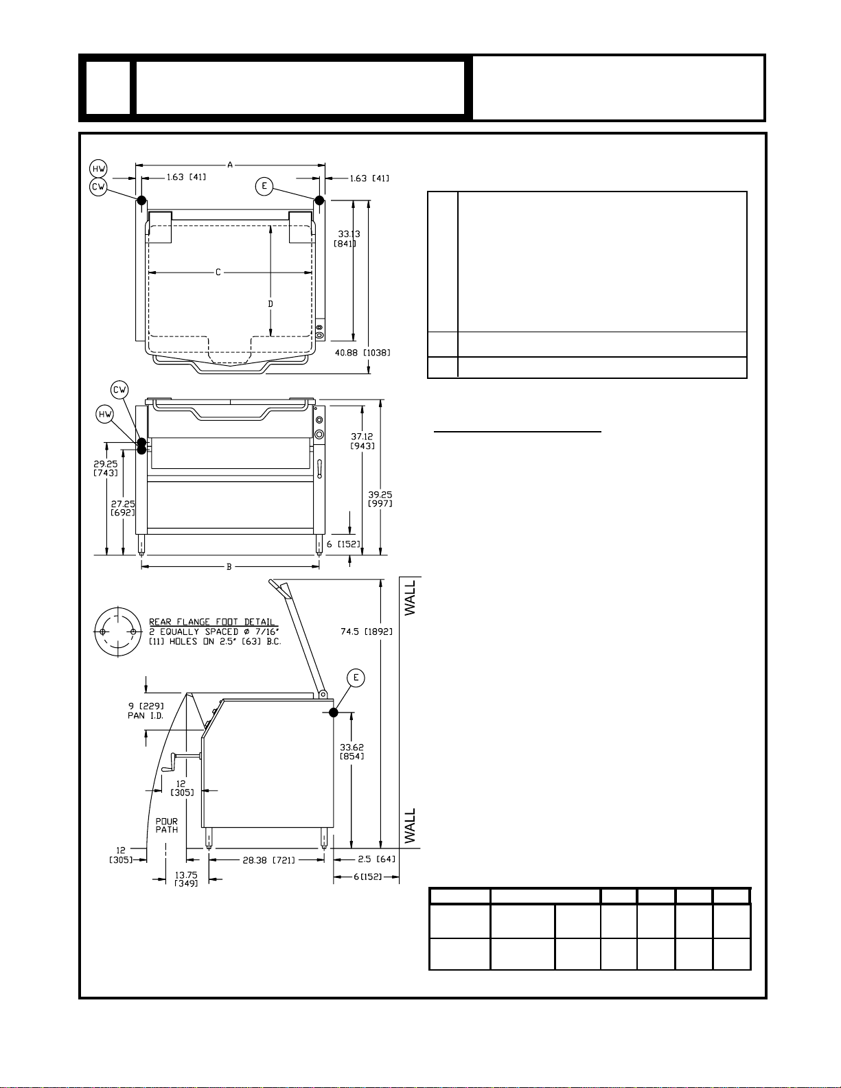
The installation location must allow adequate clearances for ser-
vicing and proper operation. A minimum front clearance of 36”,
and rear clearance of 6” is required.
INSTALLATION CODES AND STANDARDS:
Your Tilting Universe Plus Electric Skillet must be installed in ac-
cordance with:
1. Provincial and local codes, with: USA state and local codes,
or in the absence of local codes, with: The National Electri-
cal Code ANSI/NFPA-70 (Latest Edition), or in the absence-
of local codes, with: Canada CSA C22.1 Canadian Electrical
Code, Part 1.
2. ANSI/NFPA Standard #96, “Vapor Removal from Cooking
Equipment”, (Latest Edition), available from Tha National Fire
Protection Association, Batterymarch Park, Quincy, Massa-
chusetts (MA) 02269.
LEVELING AND ANCHORING THE SKILLET:
1. Place the skillet in the desired location of installation.
2. Place a carpenter’s level on the top of the skillet pan and
turn the adjustable feet to level the skillet from side-to-side-
and front-to-back.
3. Mark hole locations on the oor through the anchoring
holes provided in the rear adjustable ange feet.
4. Remove the skillet from the anchoring holes marks that you
marked on the oor and drill a hole for each marking. After
all holes have been drilled, place the skillet back into original
position.
5. Check to make sure the skillet is still level. (See Step 2).
6. Bolt and anchor the skillet securly to the oor, then seal the
bolt sand anged feet with a silastic or equivalent compound.
7. If faucet is provided, connect water supply and check
operation.
8. Turn the power on and check for proper operation.
WARNING!:
Electrical and grounding connections must comply with
the appliance portions of The National Electrical Code
and/or other local codes.
ELECTRICAL CONNECTION:
NOTE!: Do not install in such a manner that a service person
cannot remove the control box cover.
• Connect unit to a branch circuit having a voltage and circuit
type specied on the name plate and of sufcient size to carry
load. The amps per line wire for the various voltage rating are
shown in table below.
NOTE!: Supply wires must be suitable for temperature of at
least 200
o
F (90
o
C). Additionally, all wiring must conform to
the requirements of local and national electric codes. Conduit
and ttings must be watertight.
• Connect ground wire from electrical service to ground lug.
• Ensure that skillet is rmly seated on fram before checking
connection and functioning of controls.
NOTE!: Unit is equipped with an interlock switch that shuts off
current to the heating elements when skillet pan is more
than (10
o
) above normal horizontal cooking position.
• Switch on current supply to unit. Check for proper fuctioning
of controls and heating elements (See page 4, Operating
Instructions).
SERVICE CONECTIONS:
• All Internal Wiring for the skillet is complete.
• Make service connections as indicated on page 2 and elec-
trical connections above.
• If a faucet is provided, connect the water supplies and check
for proper operation.
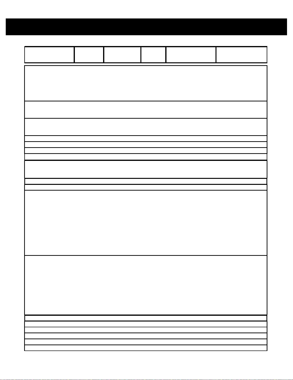
AMP PER LINE WIRE TABLE:
12 kW 220/380 Volt 18.2 18 kW 220/380 Volt 27.0
12 kW 240/415 Volt 16.7 18 kW 240/415 Volt 25.0
L # 1 L # 2 L # 1 L # 2
208 Volt 57.7 57.7 18 kW 87.0 87.0
240 Volt 50.0 50.0 18 kW 75.0 75.0
L # 1 L # 2 L # 3 L # 1 L # 2 L # 3
33.0 33.0 33.0 50.0 50.0 50.0
29.0 29.0 29.0 43.0 43.0 43.0
14.5 14.5 14.5 22.0 22.0 22.0
Amps Per Line
208 Volt
240 Volt
480 Volt
( EXPORT ONLY)
18 kW, 1 pH Unit, 60Hz
Amps Per Line
18 kW, 3 pH Unit, 60Hz
MODELS: 40P-STEL * 40P-STEM
EXPORT MODELS: 40P-STEL-LX * 40P-STEM-LX
3 pH, 4 Wire, 50Hz
Amps Per Line Wire
208 Volt
240 Volt
480 Volt
12 kW, 1 pH Unit, 60Hz
Amps Per Line
12 kW, 3 pH Unit, 60Hz
Amps Per Line
EXPORT MODELS: 30P-STEL-LX * 30P-STEM-LX
3 pH, 4 Wire, 50Hz
Amps Per Line Wire
( EXPORT ONLY)
MODELS: 30P-STEL * 30P-STEM

OPERATION
4
WARNING!: The tilting skillet and its parts are hot. Use care
when operating, cleaning and servicing the tilting skillet.
BEFORE FIRST USE:
Using a non-corrosive, grease-dissolving commercail cleaner,
clean the protective metal oils from all surface parts and inte-
rior of the skillet. Follow the cleaner manufacturer’s directions.
Rinse throughly and drain the pan. Wipe dry with a soft clean
cloth.
CONTROLS:
Red Temperature Light Illuminates when heating elements
are supplying heat to the tilting skillet.
_________________________________________________
Thermostat Turns tilting skillet ON and maintains
set temperature by controlling power
supply. Temperature settings range
from 100oF to 450oF (See Test Kitchen
Bulletin on page 6).
_________________________________________________
Hand Crank To raise and lower pan.
_________________________________________________
Tilt Switch (Optional) Push UP to raise pan; push DOWN to
lower tilting braising pan.
_________________________________________________
Timer 1 Hour mechanical timer (program
duration of cooking time).
_________________________________________________
START-UP PROCEDURE:
1. Ensure that the skillet pan is in the DOWN position.
2. Turn the THERMOSTAT dial to the desired temperature
(refer to Test Kitchen Bulletin on page 6). The RED TEM-
PERATURE light will come on.
3. When skillet pan has reached set temperature, the RED
TEMPERATURE light will go off and the heating elements
will shut off. The heating elements will cycle on and off there-
after to maintain set temperature. The RED TEMPERATURE
light will cycle on and off with the heating elements.
4. Preheat skillet pan and allow it to cycle to equalize heat
across the entire surface.
5. Water will boil faster with the lid down.
6.Turn THERMOSTAT to OFF whn skillet is not in use.
BASIC OPERATION:
1. Ensure that electric power connection has been made
correctly and that branch circuit breaker at building supply
box is ON.
2. Ensure that skillet is in full down position and clean before
using.
NOTE!: Electric power automatically shuts off when skillet is
tilted more than 10oabove normal horizontal cooking position.
3. Set thermostat at desired temperature by turning thermostat
control knob clockwise. (refer to Test Kitchen Bulletin on
page 6)
4. Preheat to desired temperature by turning thermostat
control knob clockwise. (refer to Test Kitchen Bulletin on
page 6 )
NOTE!: For best results, allow unit to cycle ON/OFF once.
5. Ensure that cover is up for most types of cooking except for
simmering, or boiling. Cover has drip-lip at rear to direct con-
densate into skillet.
6. Remove cooked food immediately to prevent over-cooking.
Tilt skillet by turning hand crank clockwise or pushing tilt
switch.
7. Lower skillet by turning hand crank counterclockwise or
pushing tilt switch.
**********************************************************************
Turn thermostat control knob counterclockwise to OFF when
no further heating is desired.
**********************************************************************
DAILY SHUTDOWN PROCEDURE:
To turn skillet OFF, turn the THERMOSTAT dial to OFF.
TILTING THE SKILLET:
1. DO NOT try to tilt skillet with lid down.
2. Make sure the receving pan is in place.
3. Turn hand crank clockwise or for power tilt, push and hold
TILT SWITCH in the ip mode until desired pan position has
been reached. The pan will empty when raised to the top tilt
position. When the braising pan is raised 10o or more, the
heating elements eill be turned off automatically.
4. Food is poured through the removable strainer into a food
receiving pan positioned under the lip of the pouring spout.
5. To lower pan, turn hand crank counterclockwise or push
and hold TILT SWITCH in the DOWN mode.

TEST KITCHEN BULLETIN
5
BATCHES
PER
ITEM HOUR QTY. YIELD QTY. YIELD
Bacon 3 Slices 350
o
12 2 lbs. 10 3 lbs. 15
Eggs 1 Egg
Boiled-Hard 1 Egg 225
o
5 50 50 75 75
Boiled-Soft 1 Egg 225
o
8 50 50 75 75
Fried 1 Egg 400
o
4 30 30 45 45
Poached 1 Egg 225
o
5 36 36 60 60
Scrambled 1 1/2 Eggs 300
o
200
o
1 18
g
al. 720 28
g
al. 1100
French Toast 3 Slices 450
o
7 35 Slices 12 50 Slices 17
Reqular Oatmeal 1/2 Cup 250
o
2 20 lbs. 500 40 lbs. 1000
Pancakes 2 Each 400
o
10 30 each 15 50 each 25
Clams 1 pt. 400
o
10 10
q
ts. 20 15
q
ts. 30
Fish Cakes 2 oz. 400
o
5 70-3 oz. 35 110-3 oz. 55
Haddock Filet 4 oz. 400
o
4 60-4 oz. 60 90-4 oz. 90
Halibut Steak 5oz. 450
o
3 60-4 oz. 60 90-4 oz. 90
Lobster 1-1 lb. 350
o
4 20-1 lb. 20 30-1 lb. 30
Swordfish 5oz. 450
o
3 50-5 oz. 50 75-5 oz. 75
Brown Gravy 1oz. 350
o
200
o
2 18
g
al. 2300 35
g
al. 4500
Cream Sauces 2 oz. 250
o
175
o
1 18
g
al. 1150 35
g
al. 2250
Cream Soups 6 oz. 200
o
1 18
g
al. 375 35
g
al. 725
French Onion Soup 6oz. 225
o
1 18
g
al. 350 35
g
al. 700
Meat Sauce 4 oz. 350
o
200
o
1 18 gal. 575 35 gal. 1100
Grilled Cheese 1 sand 400
o
8 35 sand 35 40 sand 50
Macaroni & Cheese 8oz. 200
o
2 18
g
al. 300 35
g
al. 525
Rice 4 oz. 350
o
225
o
1 20 lb.raw 320 40 lb. 650
4oz. 350
o
225
o
2 8 lb. 200 12 lb. 300
Beef
American Chop Suey 6oz. 400
o
225
o
2 18
g
al. 350 35
g
al. 700
Beef Stew 8 oz. 300
o
-- 18
g
al. 280 35
g
al. 560
Corn Beef Hash 5oz. 400
o
5 16 lb. 50 25 lb. 75
Cheeseburger 3oz. 300
o
12 7 lb. 35 10 lb. 50
Hamburger 3oz. 300
o
15 7 lb. 35 10 lb. 50
BREAKFAST FOODS
FISH
SAUCES, GRAVIES AND SOUPS
MISCELLANEOUS
MEAT & POULTRY
PER LOAD
30 Gallon 40 Gallon
PER LOADPORTION
SIZE THERMOSTAT
SETTING
Spaghetti

TEST KITCHEN BULLETIN
6
Hamburger 3oz. 300 15 7 lb. 35 10 lb. 50
Meatballs 1oz. 400
o
225
o
3 12 lb. 65 18 lb. 100
Pot Roast 2oz. 350
o
200
o
-- 120 lb. 500 180 lb. 750
Salisbury Steak 5oz. 400
o
3 16 lb. 50 24 lb. 75
Sirloin Steak 6oz. 400
o
5 15 lb. 40 22 1/2 lb. 60
Swiss Steak 4oz. 300
o
200
o
1 25 lb. 100 40 lb. 160
Chicken
Pan-Fired 350 3 50 Pieces 25 80 Pieces 40
Whole 2oz. 350 200
o
-- 16-5 lb. 200 24-5 lb. 265
Frankfurters
Grilled 2 oz. 300
o
8 22 lb. 176 33 lb. 264
Boiled 2oz. 250
o
12 16 lb. 128 25 lb. 200
Ham Steak 3 oz. 400
o
8 10 lb. 50 15 lb. 75
Pork Chops 5 oz. 400
o
4 15 lb. 50 25 lb. 75
Sausage Links 3 links 350
o
7 30 lb. 120 45 lb. 180
2 1/4's
BATCHES
PER
ITEM HOUR QTY. YIELD QTY. YIELD
Turkey
Off Carcass 2 oz. 400
o
200
o
-- 3-26-30 lb. 200 4-26-30 lb. 275
On Carcass 2oz. 400
o
200
o
-- 4-16-20 lb. 175 6-16-20 lb. 265
Canned oz. 400
o
6 30 lb. 125 45 lb. 200
Fresh
Beans oz. 400
o
3 25 lb. 125 50 lb. 250
Beets oz. 400
o
1 30 lb. 125 60 lb. 300
Broccoli oz. 400
o
3 25 lb. 125 40 lb. 200
Cabbage oz. 400
o
5 20 lb. 80 30 lb. 125
Carrots oz. 400
o
2 35 lb. 150 70 lb. 300
Cauliflower oz. 250
o
5 15 lb. 75 25 lb. 125
Corn ear 400
o
8 50 ears 50 75 ears 75
Potatoes oz. 400
o
2 40 lb. 200 60 lb. 300
Spinach oz. 225
o
10 6 lb. 25 9 lb. 35
Turnips oz. 400
o
2 20 lb. 100 30 lb. 150
Frozen
Beans oz. 400
o
6 15 lb. 60 22 1/2 lb. 90
Lima Beans oz. 250
o
4 15 lb. 60 22 1/2 lb. 90
Broccoli oz. 400
o
8 12 lb. 50 18 lb. 75
Sliced Carrots oz. 250
o
6 15 lb. 60 22 1/2 lb. 90
Baby Carrots oz. 250 3 15 lb. 50 22 1/2 lb. 90
Corn oz. 250
o
18 15 lb. 50 22 1/2 lb. 90
Baby Onions oz. 250
o
7 15 lb. 50 22 1/2 lb. 90
Peas oz. 400
o
10 15 lb. 75 22 1/2 lb. 110
Spinach oz. 400
o
3 15 lb. 75 22 1/2 lb. 110
Butterscotch Sauce 1oz. 200
o
1 18
g
al. 2330 35
g
al. 4500
Cherry Cobbler 3oz. 200
o
1 19
g
al. 750 36
g
al. 1500
Chocolate Sauce 1 oz. 200
o
1 20
g
al. 2300 37
g
al. 4500
Cornstarch Pudding 4oz. 200
o
1 21
g
al. 575 38
g
al. 1100
Fruit Gelatin 3oz. 250
o
2 22
g
al. 750 39
g
al. 1500
VEGETABLES
DESSERT ITEMS
SIZE SETTING
MEAT & POULTRY
40 Gallon
PORTION THERMOSTAT PER LOAD PER LOAD
30 Gallon

TROUBLE-SHOOTING
7
PROBLEM
Uneven Heating
Signal Light Out
Unit Fails to Heat
PROBABLE CAUSE
a. Defective element.
b. Uneven torque of element
clamp plate nuts.
c. Temperature control out of
calibration or defective.
a. Burnt out bulb.
b. Defective temperature control
or thermocouple.
c. Loose electrical connection.
a. Circuit breaker is off.
b. Malfunction of interlock
switch.
c. Contactor does not pull in.
d. Defective temperature control
or thermocouple.
REMEDY
a. Replace element.
b. Re-torque element clamp
plate nuts on bottom of skillet
(5’ pounds only/nut).
c. Calibrate or replace.
a. Replace.
b. Replace.
c. Repair.
a. Reset circuit breaker.
b. Adjust or replace.
c. Replace contactor.
d. Replace temperature control
or thermocouple.
MAINTENANCE
IMPORTANT!: DISCONNECT ELECTRICAL POWER SUPPLY BEFORE CLEANING.
DAILY CLEANING:
1. The skillet should be cleaned daily.
2. Wash the skillet with a mild detergent and hot water. If food is stuck to the surface of the skillet pan, soak it and use a
little heat to loosen the food. Then, wash with clean water and whip dry.
3. Be sure to wash under the skillet cover and rinse with clean water.
4. Check the skillet pouring lip corners to be sure they are clean. Also, wash around the exterior of the skillet. Rinse with
clean water and air dry.
WARNING!: DO NOT GET WATER ON WIRING OR CONTROLS. BE SURE TO WASH INSIDE OF SKILLET PAN, INSIDE OF
COVER INCLUDING UNDER DRIP-LIP, AND POURING SPOUT AREA.
WARNING!: THE SKILLET PAN AND ITS PARTS ARE HOT. USE CARE WHEN OPERATING, CLEANING AND SERVICING
THE TILT SKILLET.
WARNING!: DISCONNECT ELECTRICAL POWER SUPPLY AND PLACE A TAG AT THE DISCONNECT SWITCH TO INDI-
CATE THAT YOU ARE WORKING ON THE CIRCUIT BEFORE PERFORMING ANY MAINTENANCE.
ADJUSTMENT NOTE!: ALL TILTING SKILLETS ARE ADJUSTED AT THE FACTORY. AT LEAST TWICE A YEAR HAVE AN
AUTHORIZED SERVICE PERSON CLEAN AND ADJUST THE TILTING SKILLET FOR MAXIMUM PERFORMANCE.

WIRING: 208V/220V/240V
8

WIRING: 220V/380V - 240V/415V
9

WIRING: 480V
10

PARTS
11
FIGURE NO. 1 Main Assembly

PARTS
12
ITEM PART FIGURE NO. 1 30 40
NO. NO. DESCRIPTION GAL. GAL.
1 98-6031 PAN COVER ASSEMBLY 1
98-6032 PAN COVER ASSEMBLY 1
2 98-6033 LEFT HAND TRUNNION ASSEMBLY 1 1
3** 98-6034 FAUCET COVER PLATE 1 1
~NPN~ FAUCET MOUNTING PLATE PANTRY FAUCET 1 1
~NPN~ FAUCET MOUNTING PLATE DOUBLE FAUCET 1 1
4 98-6035 LEFT HAND CONSOLE TOP COVER 1 1
5 98-6036 LEFT HAND CONSOLE TILT SHAFT BEARING BRACKET 1 1
6 98-6037 LOWER CONSOLE SIDE PANEL LEFT HAND 1 1
7 98-6038 LEFT HAND CONSOLE FRONT COVER 1 1
8 97-5577 GRIP HANDLE 1 1
9 98-6040 CRANK SHAFT 1 1
10 98-6041 INPUT SHAFT ADAPTOR 1 1
11 98-6042 ADJUSTABLE BULLET FOOT 2 2
12 98-6043 RIGHT HAND FRONT CONSOLE COVER 1 1
13 98-6044 DECAL 1 1
14 98-6045 TIMER COMPLETE WITH DIAL 1 1
15 98-6046 THERMOSTAT DIAL 1 1
* 98-6047 ROTARY SHAFT SEAL 1 1
16 98-6048 PILOT LIGHT - TEMPERATURE, RED 1 1
17 98-6049 RIGHT HAND CONSOLE TOP COVER 1 1
18 98-6050 SPRING RETAINER 2 2
* 98-6051 Hx. BOLT 3/8-16 x 1 1/2 4 4
* 98-6052 WASHER 3/8 STAINLESS STEEL 4 4
* 98-6053 SPACER 4 4
19 98-6054 GEAR BOX ASSEMBLY 1 1
19A 97-6396 WORM GEAR
20 98-6055 FLANGE ADJUSTABLE FOOT 2 2
21 98-6056 LOWER CONSOLE SIDE PANEL RIGHT HAND 1 1
22 98-6057 TILT SHAFT 1
98-6058 TILT SHAFT 1
23 98-6059 TILT ARM EXTENSION 2 2
24 98-6060 ARM, LIFT 2 2
25 98-6061 ROLL PIN, 1/4 x 1 1/2 STAINLESS STEEL 2 2
98-6062 Hx. BOLT 1/4 x 1 1/2 STAINLESS STEEL 2 2
26 91-9145 SPRING, RIGHT HAND 1 1
91-9144 SPRING, LEFT HAND 1 1
27 98-6065 FLUE ASSEMBLY 1

PARTS
13
ITEM PART FIGURE NO. 1 30 40
NO. NO. DESCRIPTION GAL. GAL.
27 98-6066 FLUE ASSEMBLY 1
98-6065 FLUE ASSEMBLY 1
98-6066 FLUE ASSEMBLY 1
28 98-6067 RIGHT HAND TRUNNION ASSEMBLY 1 1
98-6068 SWIVEL BRACKET 1 1
29 98-6069 LIQUID TIGHT CONNECTOR 1/2” 1 1
98-6070 LOCKNUT 1/2” 1 1
30 97-5702 CORD SET 1 1
31 98-6072 POST ASSEMBLY 2 2
32 97-5545 CAP SCREW 5/16-18 x 3/4 STAINLESS STEEL 8 8
33 97-5352 LOCK PIN 2 2
34 97-5343 END LOCK PIN 2 2
35 98-6073 STATIONARY DISC 2 2
36 98-6074 CORE 2 2
37 97-5160 SPRING 2 2
38 98-6076 ROTARY DISC 2 2
39 97-5356 END STOP PLATE 2 2
40 98-6078 FRONT COVER PANEL (MODULAR UNITS) 1
98-6079 FRONT COVER PANEL (MODULAR UNITS) 1
41 98-6080 BACK COVER PANEL (MODULAR UNITS) 1 1
98-6081 BACK COVER PANEL (MODULAR UNITS) 1
42 98-6082 VENT COVER 1 1
43 98-6083 SWIVEL SPACER 1 1
44 91-9262 ARM 1 1
45 98-6084 KNOB 1 1
46 98-6085 SWIVEL BASE 1 1
47 98-6086 WASHER 1/4 STAINLESS STEEL 1 1
48 98-6087 Hx. Hd. SCREW 1/4-20 x 3/8 STAINLESS STEEL 1 1
49* 98-6013 POUR LIP STRAINER 1 1
* NOT SHOWN
** SELECT AS REQUIRED

PARTS
14
ITEM PART FIGURE NO. 3
NO. NO. DESCRIPTION QTY.
1 98-6131 COMPONENT MOUNTING BOARD 1
2 97-5441 GROUND LUG 1
3 97-4617 TERMINAL BLOCK SECTION ASSEMBLY 3
4 98-6132 FUSE HOLDER 1
5** 97-5476 FUSE, 3A, 250V (120V UNIT) 1
98-6134 FUSE, 1A, 250V (220V UNIT) 1
6 98-6189 CONTACTOR 1
7 98-6190 TEMPERATURE CONTROL 1
8* 98-6138 TRANSFORMER, 220-120V, 100VA (220V UNIT) (NOT
SHOWN)
1
** SELECT AS REQUIRED
FIGURE NO. 3 Control Circuit Components

PARTS
15
ITEM PART FIGURE NO. 4
NO. NO. DESCRIPTION QTY.
98-6014 2” DRAW-OFF VALVE ASSEMBLY
1 98-6155 ACORN NUT 10-24 UNC 1
2 97-5413 HANDLE STAINLESS STEEL 1
3 97-5069 GLAND NUT 1
4 97-5072 BONNET 1
5 97-5078 “O” RING 1
6 97-5075A STEM ASSEMBLY 1
7 98-6156 VALVE BODY 1
8* 98-6010A DRAW-OFF STRAINER (OPTIONAL) 1
* NOT SHOWN
FIGURE NO. 4 Draw-Off Valve Assembly

PARTS
16
FIGURE NO. 5 Optional Motor Tilt Components (LX Models)

PARTS
17
ITEM PART FIGURE NO. 5
NO. NO. DESCRIPTION QTY.
1 98-6139 TILT SWITCH 1
2 97-5793 SPRING TENSION PIN 3/16 x 1 1/4 LONG 1
3 98-6140 UNIVERSAL JOINT 1
4 98-6141 SET SCREW 5/16-18 x 3/8 2
5 98-6142 MOTOR MOUNTING BRACKET 1
6** 97-5351 Hx. SCREW 5/16-18 x 3/4 3
~NPN~ FLAT WASHER 5/16 3
~NPN~ LOCK WASHER 5/16 3
7 98-6144 MOTOR 1/20 HP 230V 1
8 98-6146 CAPACITOR 440 VAC 2.0 MFD (230V MOTOR) 1
9 98-6147 MOTOR ACCESS PANEL 1
10 98-6148 Hx. BOLT 1/4-20 x 1/2 2
11 98-6149 SWITCH MOUNTING BRACKET 1
12 98-6150 SCREW 6-32 x 1 4
13 97-5414 LIMIT SWITCH 2
14 98-6151 CAM ACTUATOR 1
15 98-6152 SET SCREW 1/4-20 x 1/2” 2
16 97-5642 HIGH LIMIT THERMOSTAT 1
17** 98-6153 FUSE 3/4 AMP TIME DELAY (120V MOTOR) (NOT SHOWN) 1
98-6154 FUSE 0.3A TIME DELAY 250V (230V MOTOR) (NOT SHOWN) 1
98-6132 FUSE HOLDER (NOT SHOWN) 1
** SELECT AS REQUIRED

PARTS
18
FIGURE NO. 6 Heating Element Pan Assembly
Other manuals for 30P-STEL
2
This manual suits for next models
3
Table of contents
Other Market Forge Industries Skillet manuals